Design a Moon Lander in Fusion 360
by Airbus Foundation in Teachers > 3D Design
11606 Views, 13 Favorites, 0 Comments
Design a Moon Lander in Fusion 360
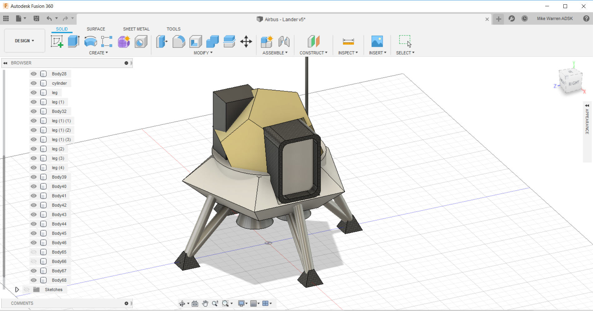
How do you get to the Moon? By rocket, of course. But how do you construct it so it can break through the Earth’s atmosphere? How can you wrangle it into a trajectory to your destination? Build each of your rocket’s components and customize your work. Then think about how far you need to go – and how you’ll land when you get there! We'll be focusing on the last part in this project: how do you land when you get there.
Setting Foot on the Moon
A manned spacecraft needs a soft landing, but it’s all in the timing. Fire up your thrusters and hope you’ve picked the right spot to touch down.
The future of space travel lies in the hands of designers and engineers, just like you. In this Instructable we'll explore designing a Moon Lander using Fusion 360, a professional computer aided design program that has everything you need from parametric design to rending your final design.
Below is the Moon Lander design we will be making together. Take a moment to interact with the model below and see it from all angles before we get started.
Let's design the next chapter in space travel!
Polyhedron in Fusion
Start by downloading Fusion 360, and making a free account.
Fusion 360 works by creating 3D models from 2D sketches on a workplane. Since Fusion 360 is parametric, you can make changes to your sketches at any time and the 3D shapes derived from those sketches automatically updates to he new values. You may find using this feature helpful if your design isn't working the way you want.
For this Moon Lander we'll start by designing the capsule, and then attach parts to that.
Although we can design the polyhedron in Fusion 360 with a sketch, it can be a little cumbersome. That's why i am going to show you two ways to tackle this problem: the first using only Fusion 360, and the second by importing a polyhedron from Tinkercad directly into Fusion (bypassing the following steps).
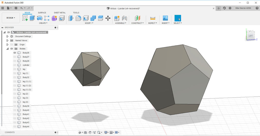
Here are two polyhedrons, the one on the left was imported from Tinkercad and the one on the right was created in Fusion 360. There is no "right" way to do this, as there are benefits to both approaches.
Let's start with making a polyhedron in Fusion 360.
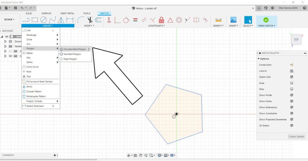
Start a new sketch and use the floor plane as our sketch surface. Go create > polygon > circumscribed polygon. Make your polygon any size you wish and finish the sketch.
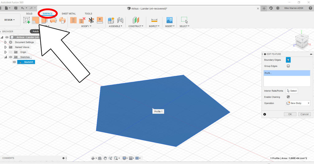
From the top tool ribbon find the surfaces tab and switch over to it, then click on the patch icon to patch our sketch into a surface we can edit.
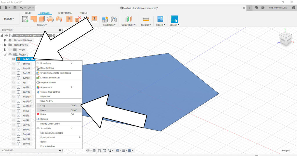
Find your new surface shape in the directory on the left side of the screen and right click to bring up a context menu. We will want to copy and then paste this polygon.
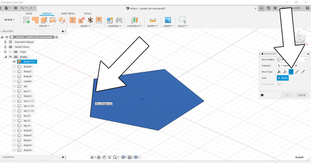
Select one of the polygon surfaces (either the original or the copy) and then use the move/copy command M. The menu that pops up allows us to specify the move type, we want rotational move to move the surface along a rotational axis. Next, select the axis to rotate around, in this case pick one side of the polygon, I chose the left side where the arrow is pointing.
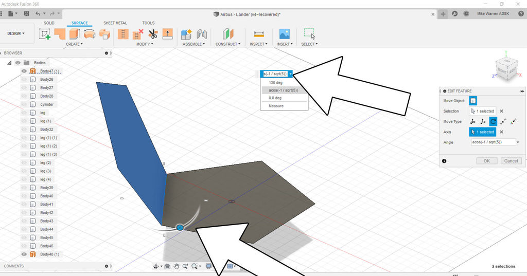
When you pick a side to rotate around a handle will appear and allow you to manually rotate the piece as you like. Instead of eyeballing the placement or using a numerical value, we will use a formula to get this exactly right. In the text field that appears when you try to rotate, enter this formula:
<strong><em>acos(-1/sqrt(5))</em></strong>
This formula gives us the exact angle we need to make a seamless array from this angled piece and around the base to form half of our polyhedron. Click OK to finish the command.
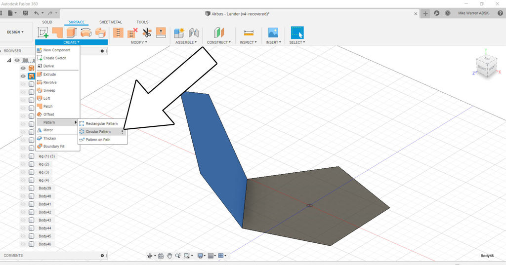
Select the tilted polygon and then use create > pattern > circular pattern to make an pattern around the bottom polygon.
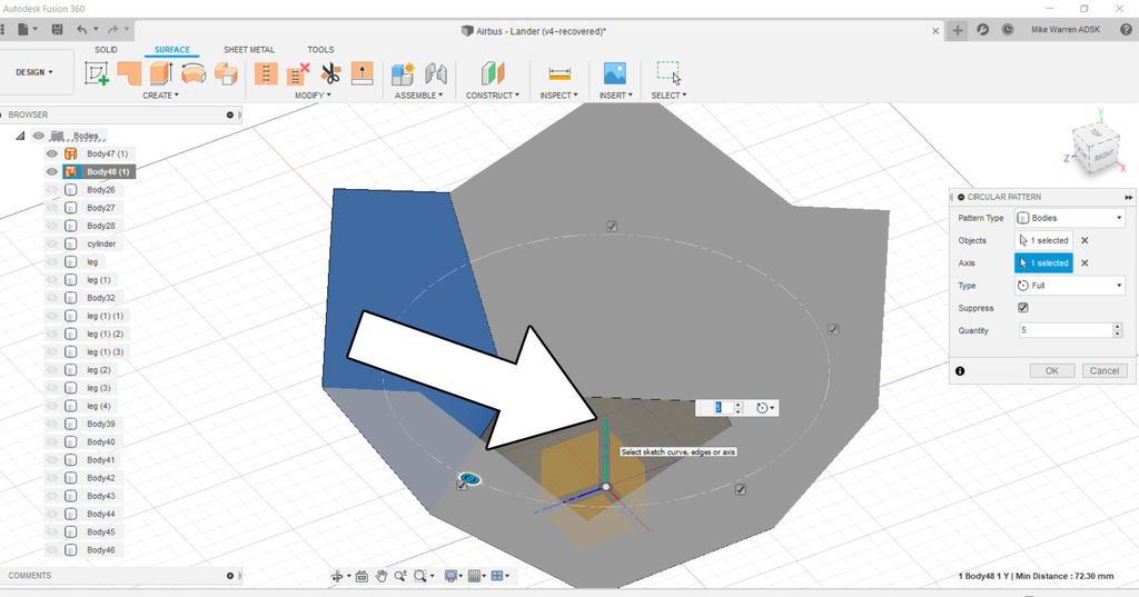
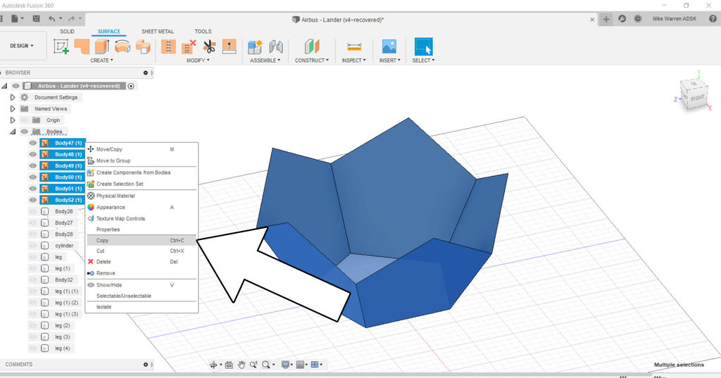
Using the same commands as before, we are going to copy the shapes we just made, then make a copy, then rotate the copy around one of the edges.
Select the 6 surfaces (5 sides and 1 base), then copy and paste.
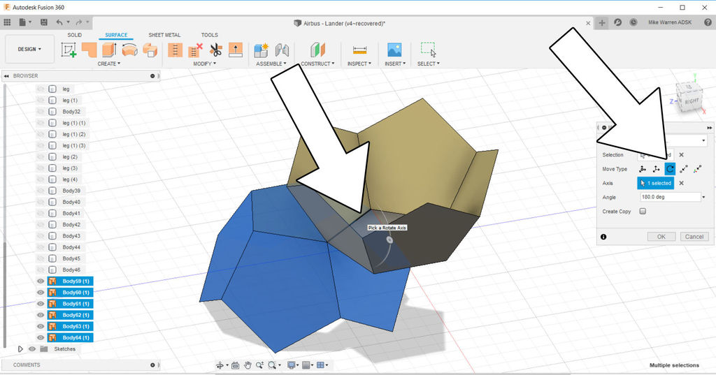
Select the copies and use move/copy to bring up the context menu that allows a rotational move type, use any side of the base to rotate around. We want to rotate 180 degrees. Push OK to finish the command.
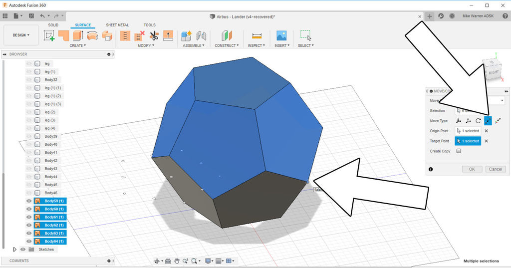
As you probably noticed, the top and bottom are the right orientation but not aligned. The last step is to select the rotated surfaces and use move/copy and then use the point to point move type. chose a vertex from the rotated surfaces and then chose the corresponding vertex on the upright piece.
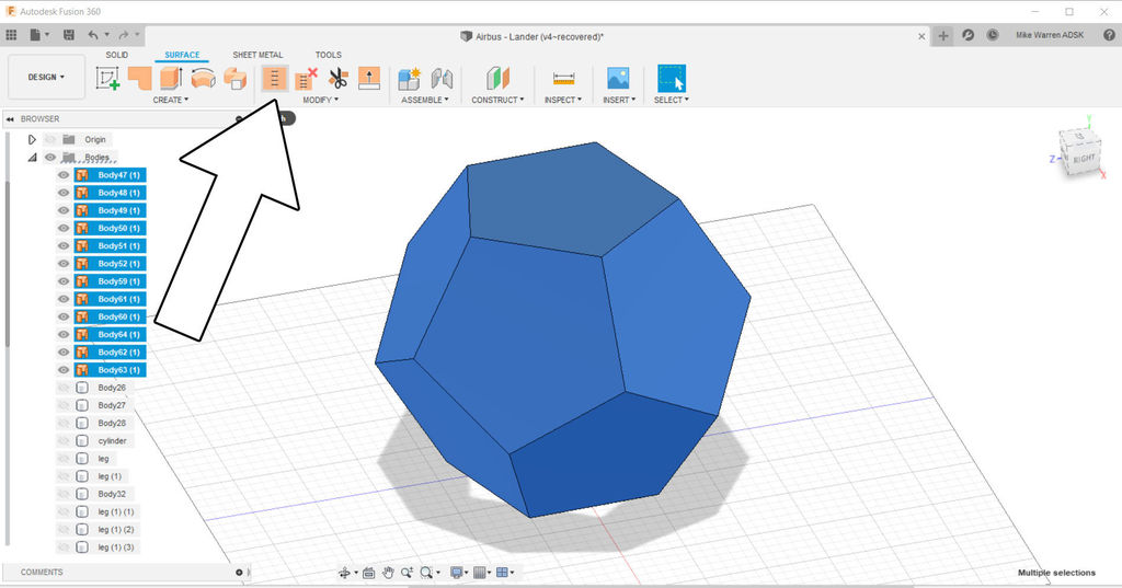
To finish the shape we will stitch the surfaces together to make a body.
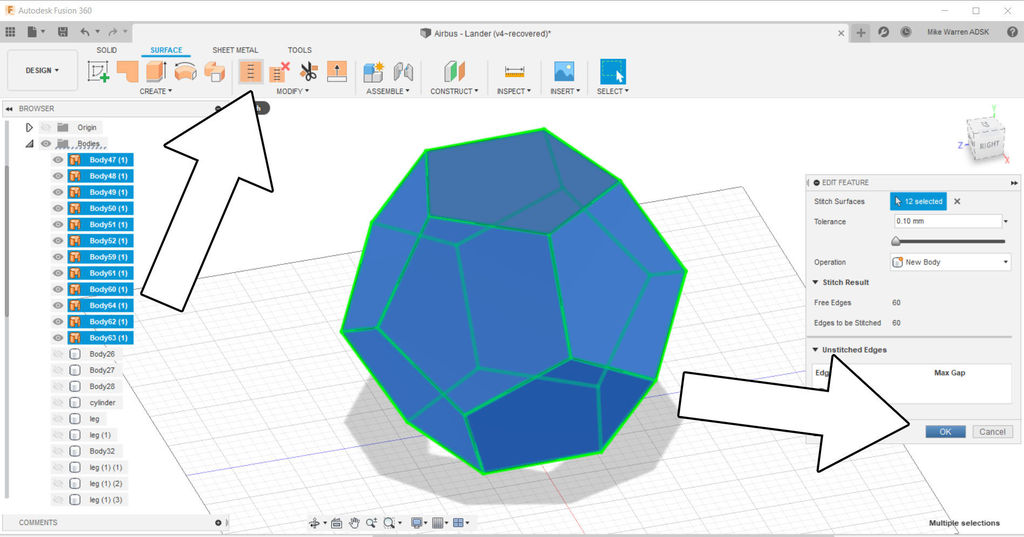
Press OK to finish the command.
You now have a polyhedron made in Fusion 360. Switch back over to the solid tab to see the body in the left side directory. We will use this as the capsule for our Moon Lander.
Polyhedron From Tinkercad
Sometimes there are easier ways to create basic shapes, like using Tinkerad. Tinkercad is a free browser based modeling software that comes loaded with a library of shapes for you to use.
Start a new design in Tinkercad and look for the isoheadron shape in the Basic Shapes library on the right side of the screen.
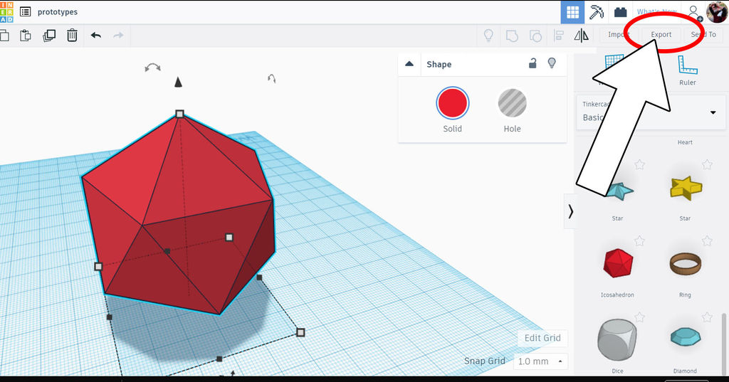
Drop that shape into the workplane. Select the shape and then use export on the top right of the screen to export the shape as an STL file. remember where you saved this file on your computer.
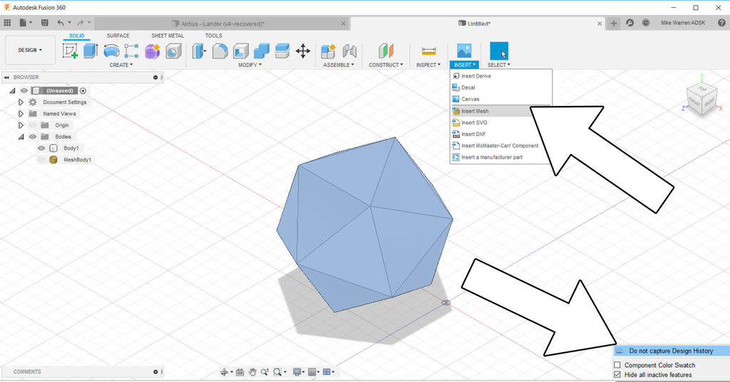
Before importing this STL into Fusion 360, we need to prepare the program to accept non-native geometry into the workspace. On the lower right side of Fusion there is a gear icon we can select asking the program do not capture Design History. We need to do this as Fusion 360 has no control of external geometry imported into the program. We will turn design history back on after inserting the STL.
Once design history is turned off, in the top toolbar find insert > insert mesh. Then, find your STL file saved from before and select it to insert into the design.
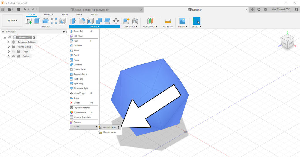
The last step is to select the inserted STL then modify > Mesh > Mesh to BRep. This will convert the STL mesh into a solid shape which we can work with.
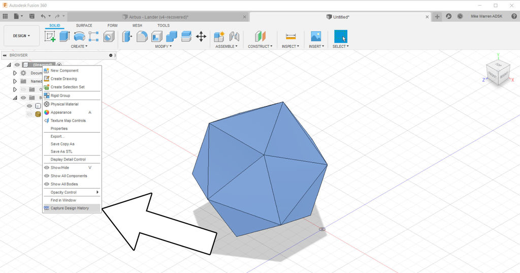
To turn on the design history again, right-click on the top element of the folder tree on the left side of the screen and enable capture design history.
Whichever way you want to use to get here, either purely in Fusion 360 or by using Tinkercad, is up to you. Once we have the basic capsule shape in the workspace we can start designing the rest of the model.
Lander Base
With the capsule portion figured we can turn our attention to the Moon Lander base.
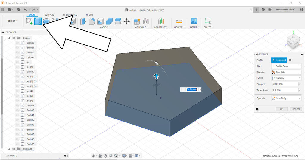
Using the same sketch geometry that we built the polyhedron from, we can extrude a new body from that sketch.
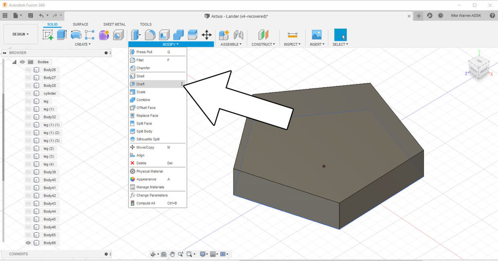
We want to add a taper around this body to give sloped sides to our Lander. For that we'll use modify > draft command.
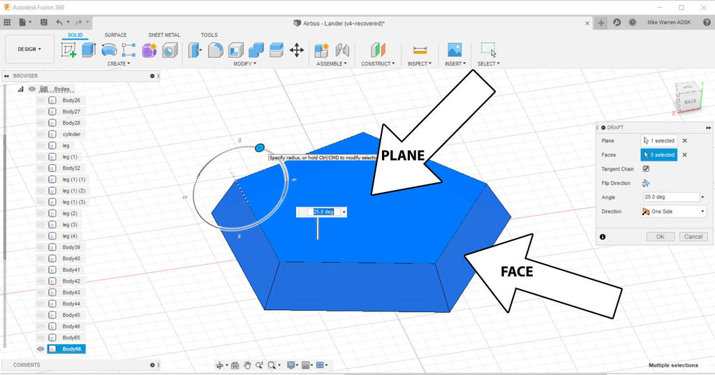
With draft selected a new menu will pop up. Select the top of the body as the plane, then select each side of the body as the faces. A rotational icon will appear over the body and allow you to manually set the draft angle to the body; I went about 25 degrees. When you are happy with the shape press OK to finish the command.
This base and the polyhedron form the upper part of the Moon Lander. We can move these elements in the right place in relation to each other, and then turn our attention to the landing gear.
Moon Lander Legs
The landing legs are made up of struts and a foot pad. We will start with the foot pad.
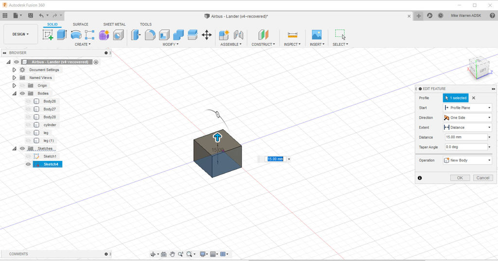
We will use the same draft command to create a tapered box for our lander foot. Use create > box to make a bx on the floor plane, I used about 15mm³ box. We can always scale it later.
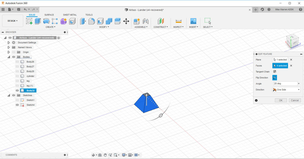
Select the lander foot body and use modify > draft to open the draft menu, then use the top as the plane and the sides as faces, then move the rotational handle to create the sloped sides of the lander foot.
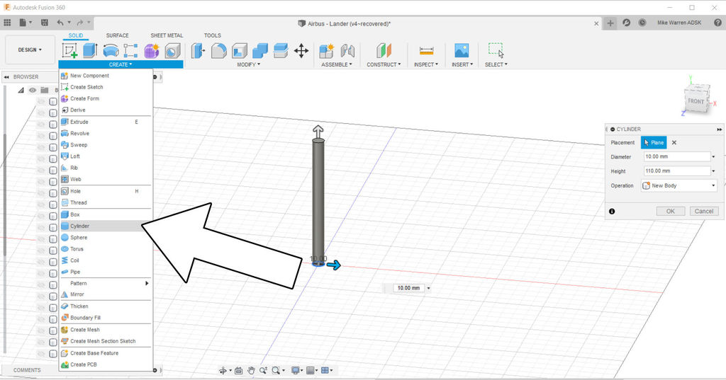
To make the landing struts I used create > cylinder and created a circle on the floor plane about 10mm in diameter and then stretched it so it was tall. If you're not happy with the sizing there's a tool in modify > push/pull that will allow you to click on a shape face and push or pull it to make it the right size.
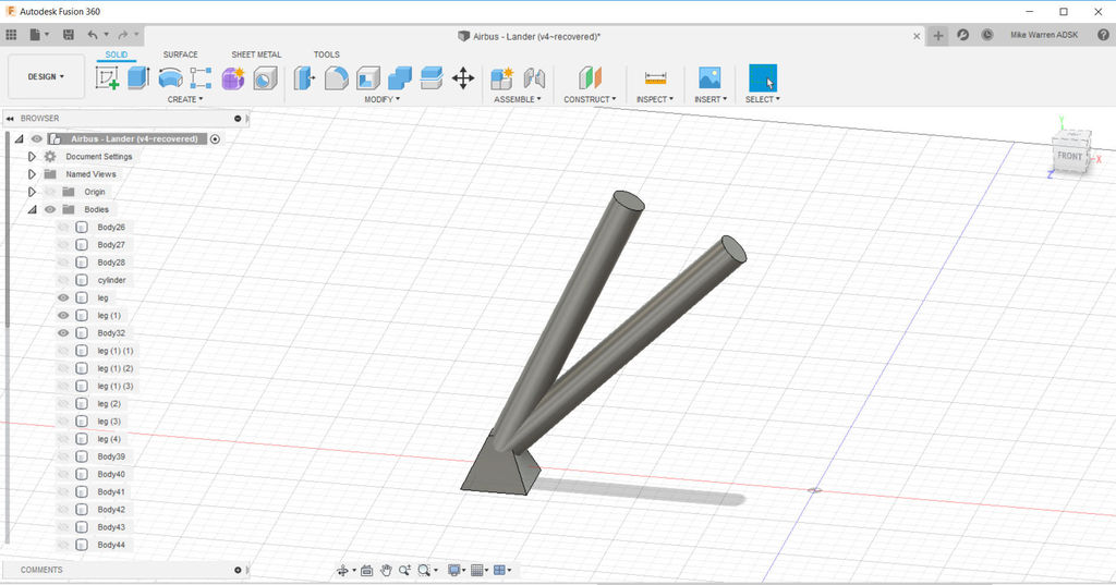
The cylinder was stacked on top of the landing foot and then rotated about 15 degrees. A copy of the strut was made and rotated another 15 degrees to double up the struts.
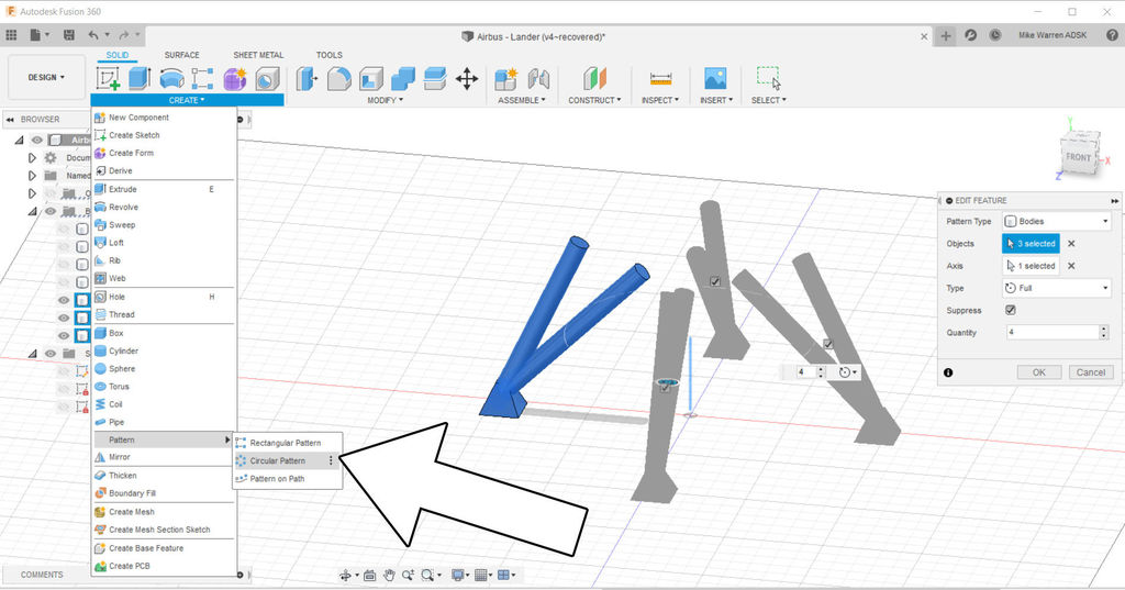
With one landing leg complete we can create > circular pattern to make the remaining legs. I used the origin point vertical axis on the workplane to array my legs around. simply move your model off to the side if your legs are too close to the origin point.
Snapshot
Pausing here to see where our design is at. With the bodies visible in the directory tree on the left I can move bodies around to here they need to be in relation to each other.
I found that the transition from polyhedron capsule to the drafted base was not as nice as I wanted, so I added another shape through create > cylinder and sized it appropriately.
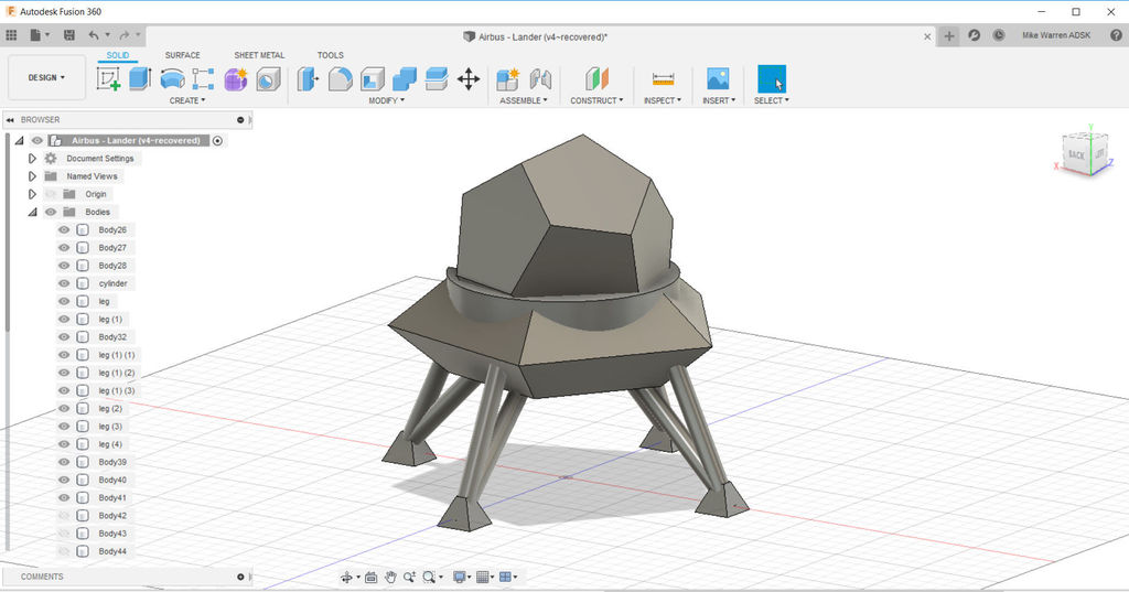
The great thing about design software like Fusion 360 is that you can easily make changes to your design by using the timeline on the bottom of the screen. This timeline remembers all the commands used and allows you to modify them. Simple right click on any action and edit feature to change things like the draft angle, the number of items in a pattern, and even the geometry in a sketch that bodies are derived from.
Entry Hatch
With the main lander design complete we can think about access to the capsule for the astronauts. For this we'll make a new sketch and design a doorway with a frame.

Make a new sketch and sketch on one of the side planes. This will change your viewport to looking at your Lander in profile. Create > Rectangle and make a doorway shape. When your door shape is done, and while still in the sketch environment, use modify > offset and click on your rectangle to make an offset rectangle. This offset will be the frame around our entryway. Click OK to finish the sketch.
The image above shows my sketch on the side of my Lander. I made it into an animation as seeing the sketch under the solid capsule shape was difficult. This is just to show you my placement of the doorway.
Finish the sketch to return to the modeling interface.
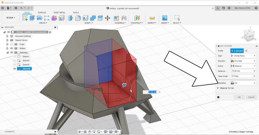
Using the offset rectangle and the inner rectangle, select both sketches and create > extrude and pull the extrusion through the capsule, on the extrude menu select cut as the operation to cut the sketch shape through the existing bodies. Click OK to finish the command.
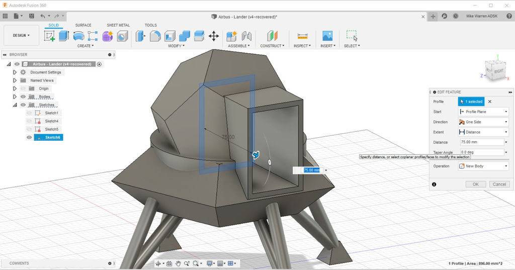
Now we will use only the offset sketch and extrude again, only this time we'll use the new body operation and pull out the sketch to make the frame for our entryway. Click OK to finish the operation.
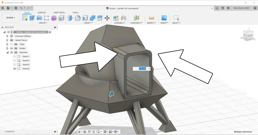
A design choice was made to fillet the edges of my entryway. With modify > fillet each edge of the extruded sides were selected and pressed inwards using the mouse to round the edges.
The last action was to to a final extrude of the inner rectangle sketch and make a new body for the doorway inside the frame.
Thrusters
To make the thrusters I started another new sketch and selected the bottom of the lander for the sketch surface.
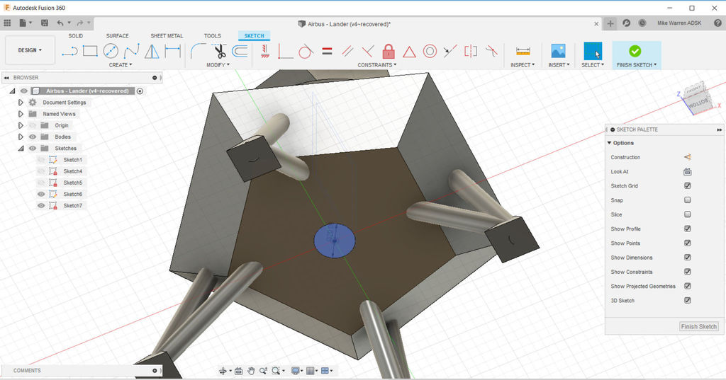
With a new sketch on the bottom of the Lander, I used create > circle to make a circle for one thruster. Then, finish sketch to return to the model interface.
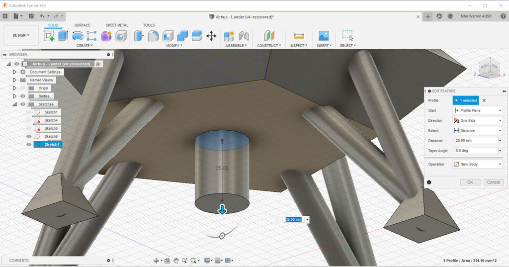
Using create > extrude the circle sketch was pulled downward to make a short cylinder.
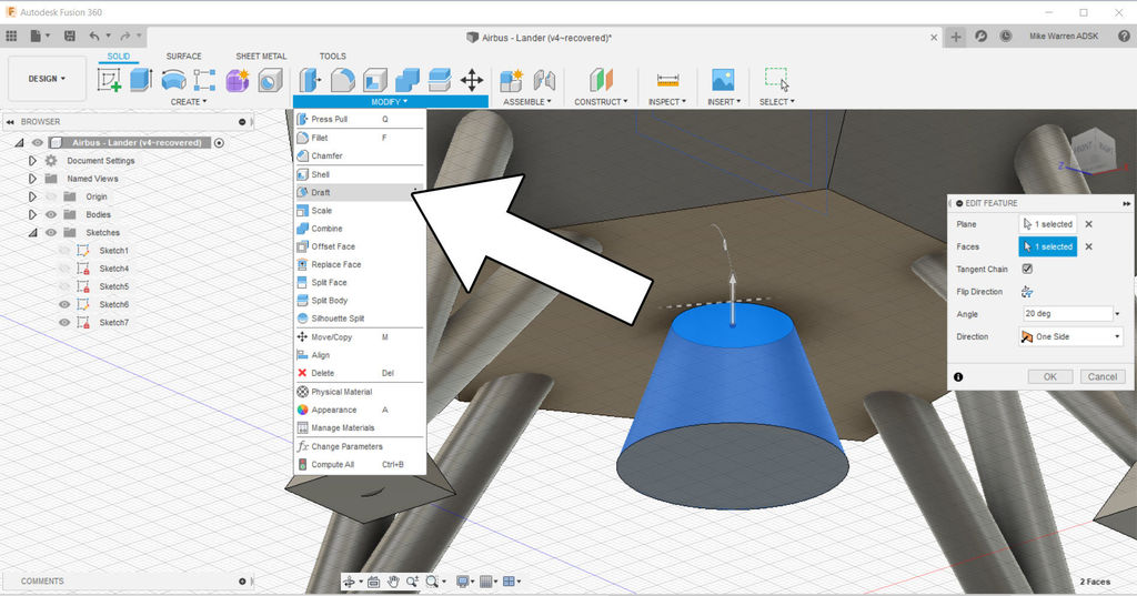
Using the modify > draft command we can taper the top of the thruster to make the familiar cone shape that thrusters have. Click OK to finish the command.
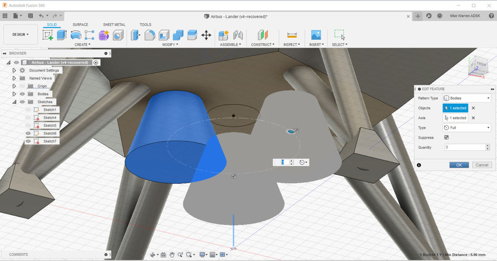
Next, we'll move the thruster body off to the side. Select the thruster body and create > circular pattern to create 2 more thrusters, using the center of the Lander as your axis point. Click OK to finish the command.
This Moon Lander is mostly complete. With the skills learned in this Instructable you can add on a few more design embellishments to make your Moon Lander unique. Maybe there is a storage bay with extra supplies in your lander, or antennae to communicate with the Moon Base? Use your imagination to add some design elements to your Moon Lander.
Appearance
The last step is to apply some appearance colors to your model and tell the story of your Moon Lander. By not combining our bodies or joining them together, we have the option of coloring each component separately.
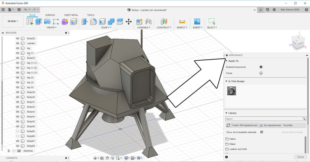
To add material appearances use modify > appearance to bring up the appearance menu. Scroll down and find folders with materials and colors. Drag a material you like from the folder and drop it on a component to have it change appearance.
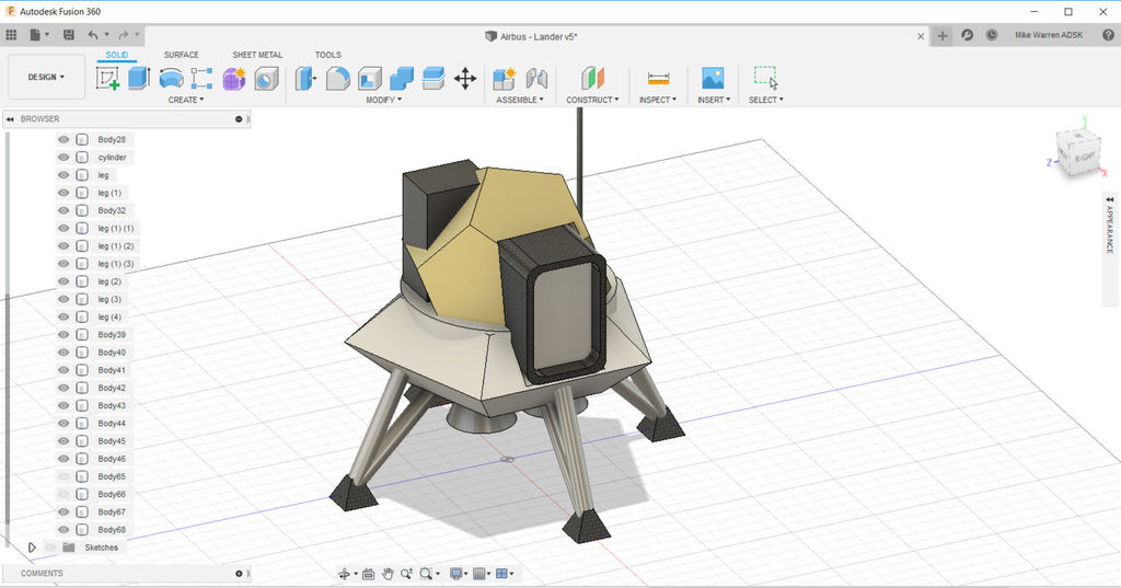
Here is what my Lander looks like after applying a new appearance. From here you can use the render option from the dropdown menu in the top left to create a rendering of your Lander and see how your materials look.
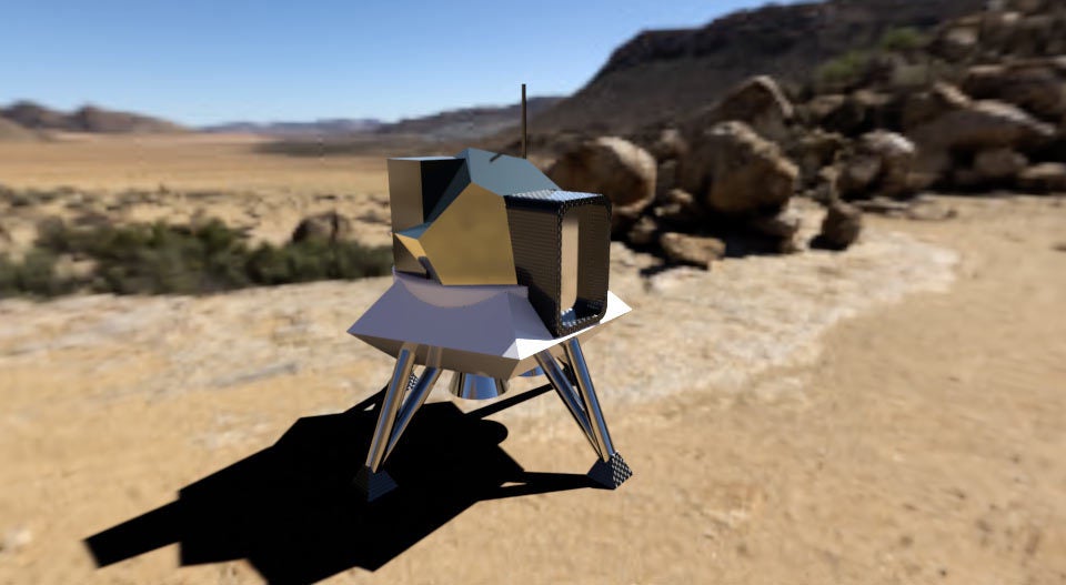
When you are done, upload your Moon Rover designed in Fusion 360 in the comments below.
Happy making :)
Take Your Design to New Heights!
This tutorial was created as part of the Moon Camp Challenge, a yearly 3D design competition by the European Space Agency and the Airbus Foundation, in partnership with Autodesk.
If you're up for the challenge, head out to the competition platform here, find many other moon related 3D design tutorials and submit them to potentially win amazing prizes!