Design Your Own Perplexus for Digital Fabrication
by Zaphod Beetlebrox in Workshop > 3D Printing
10457 Views, 16 Favorites, 0 Comments
Design Your Own Perplexus for Digital Fabrication
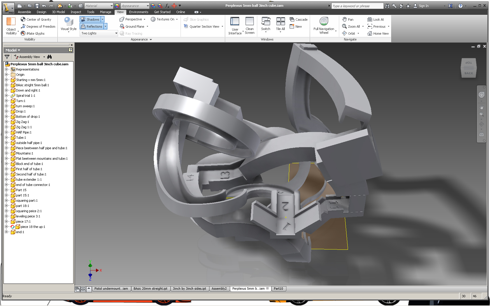
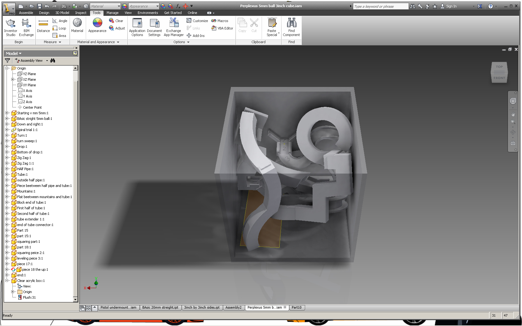
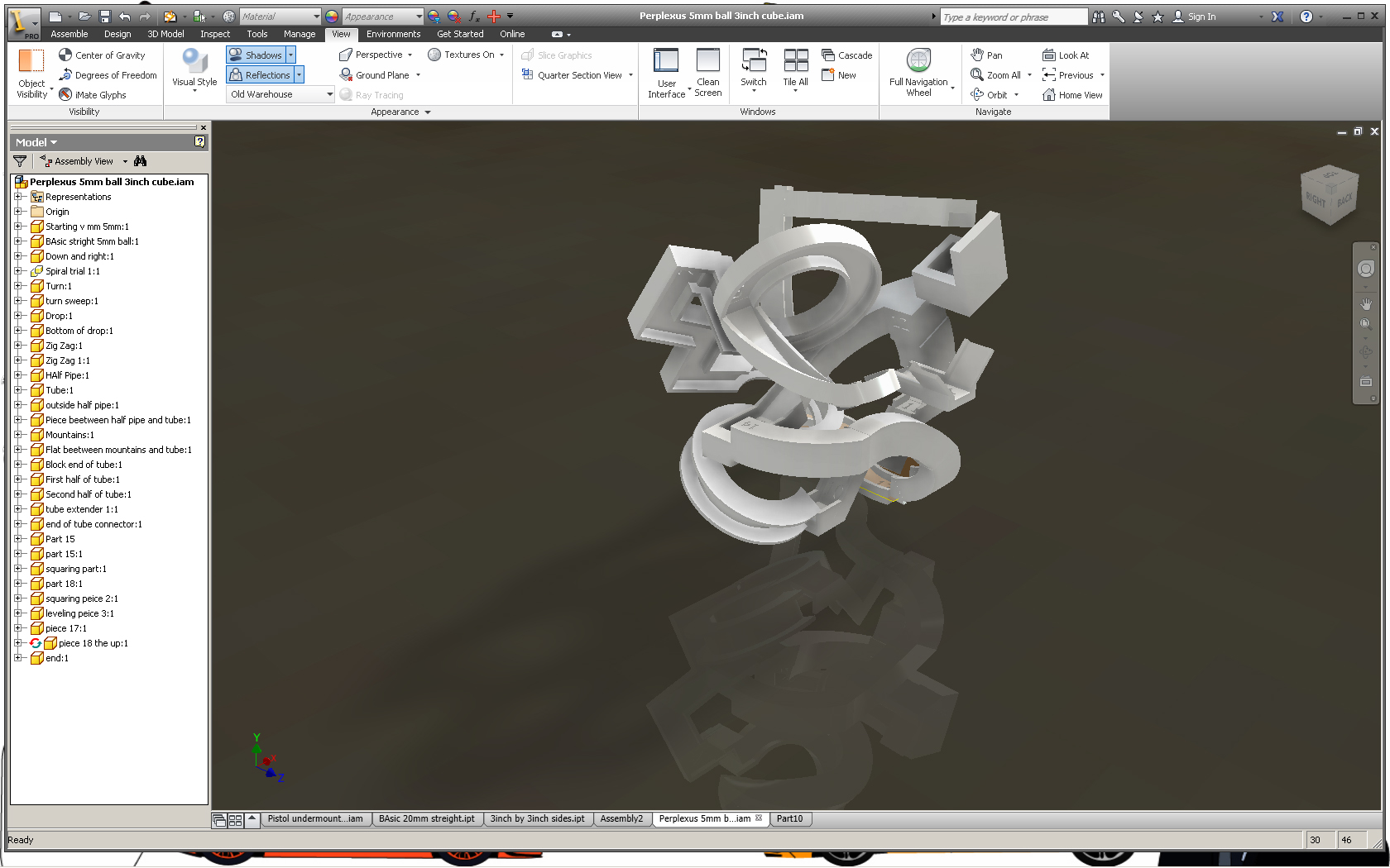
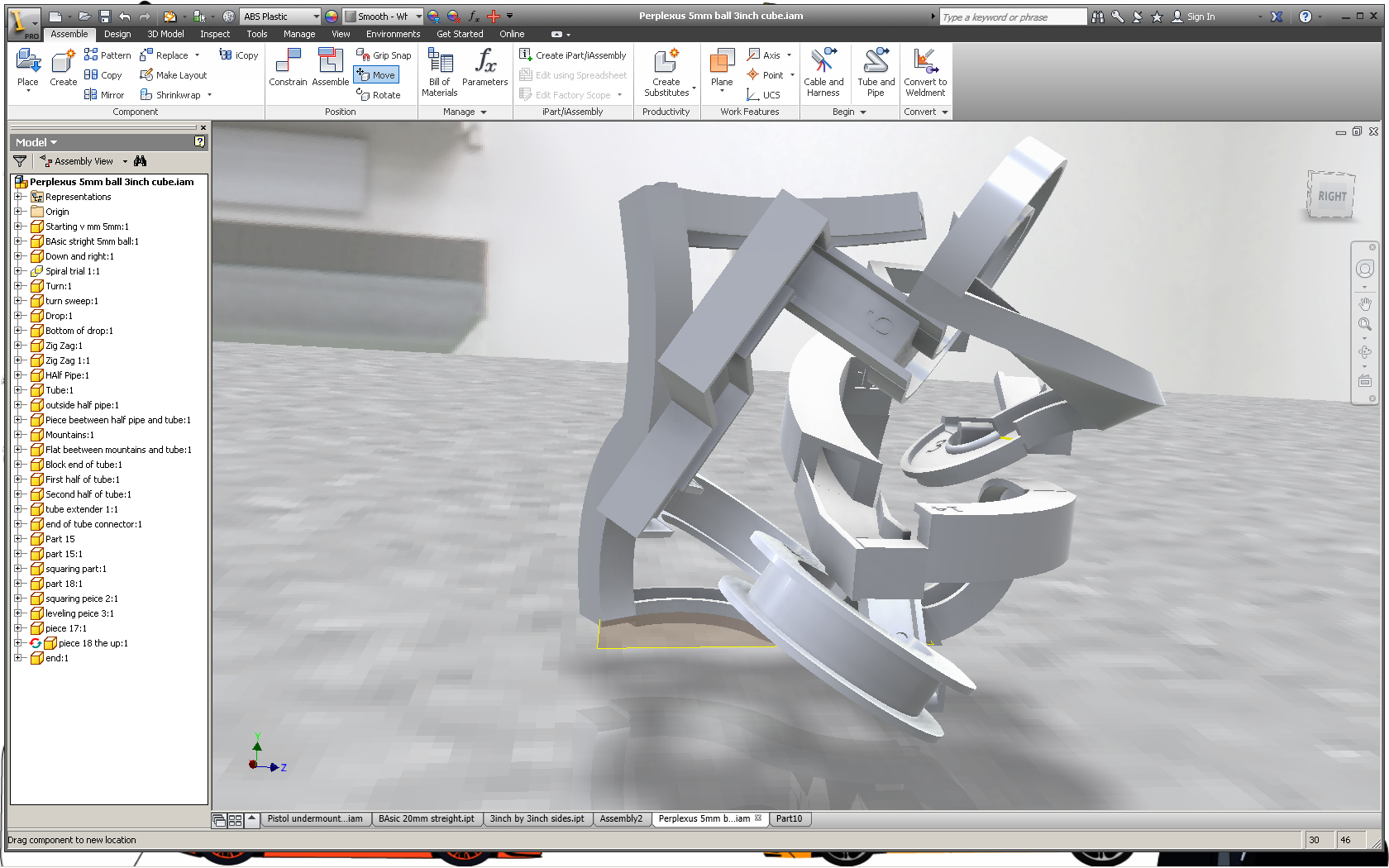
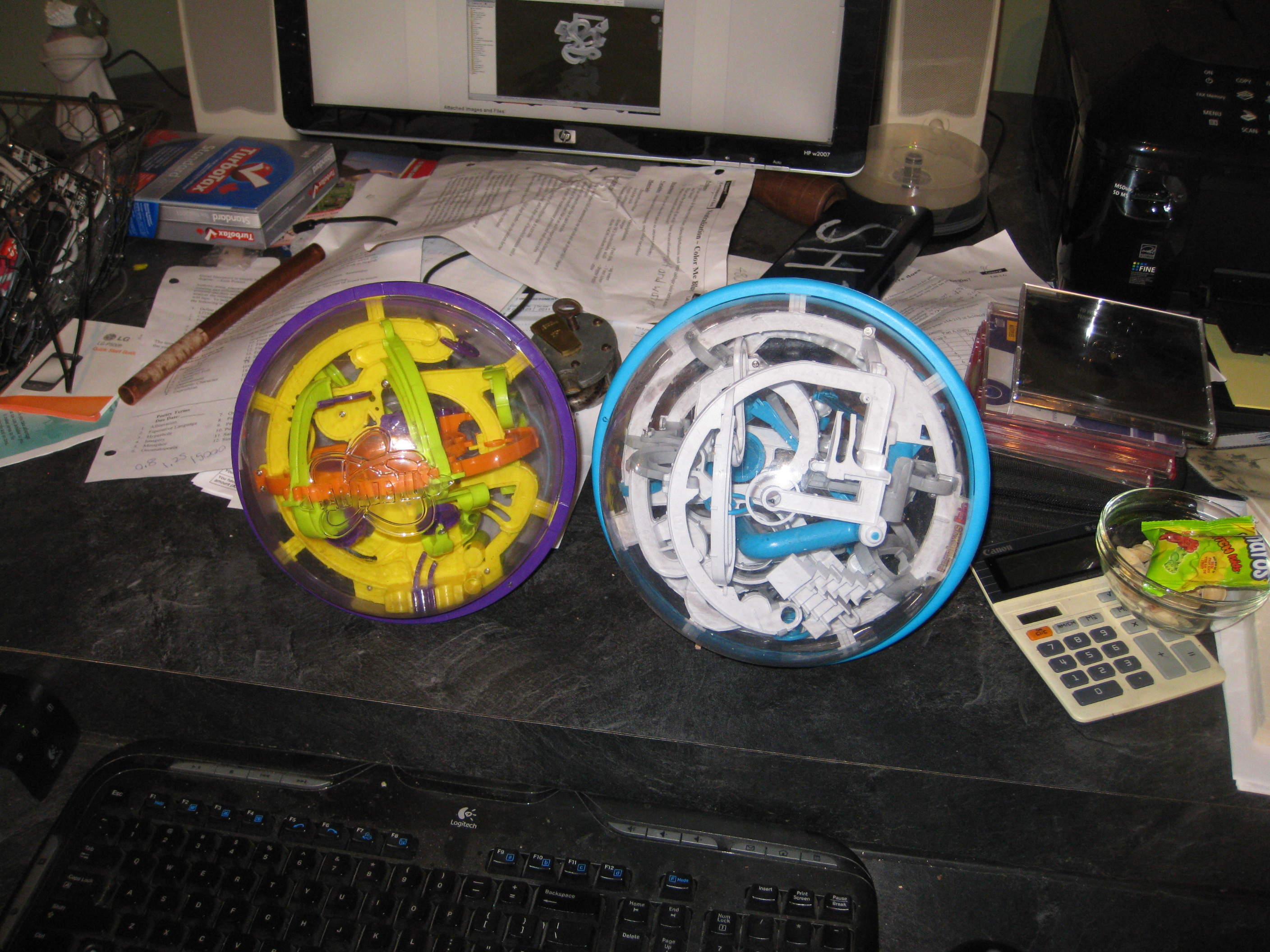
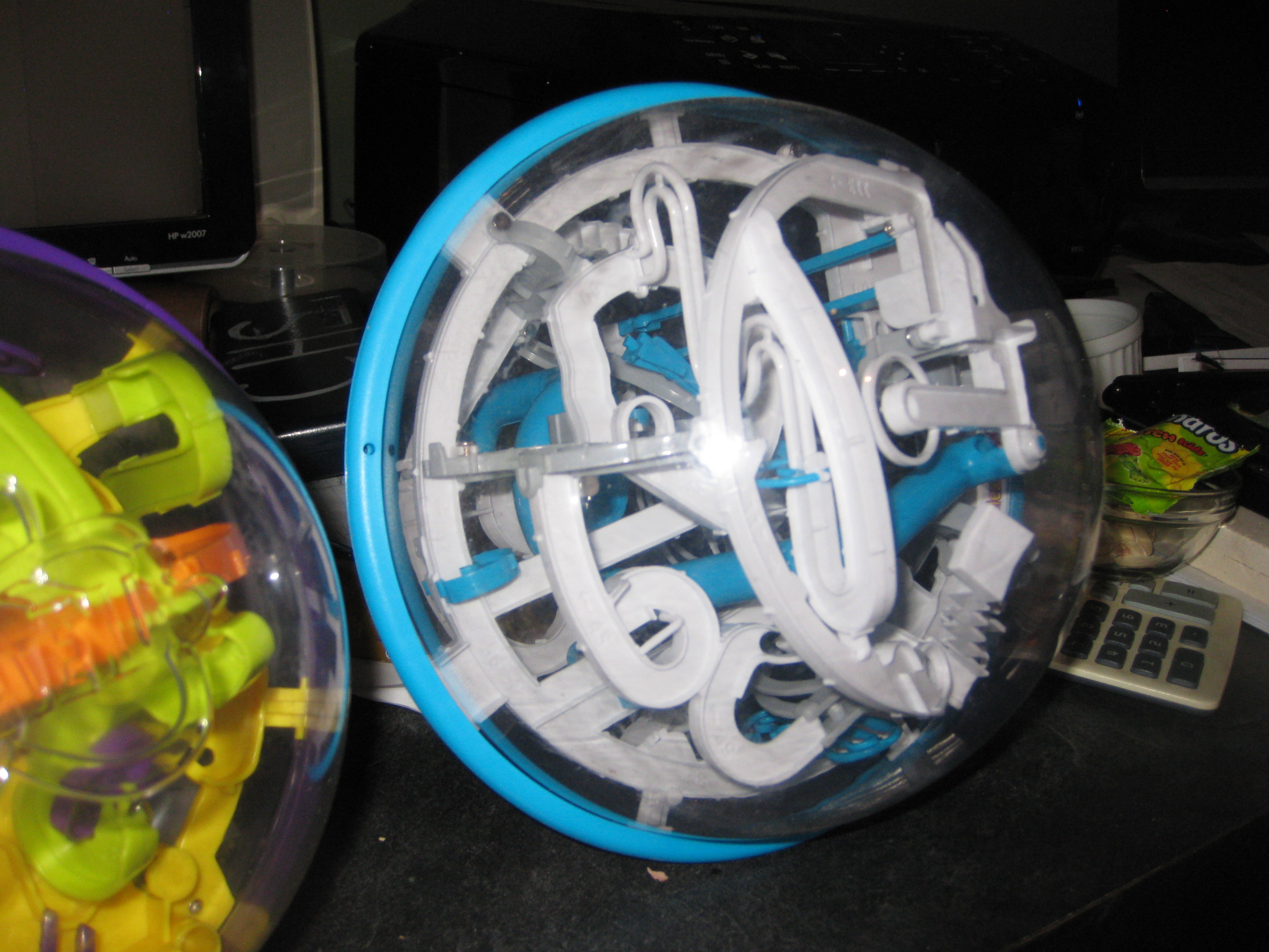
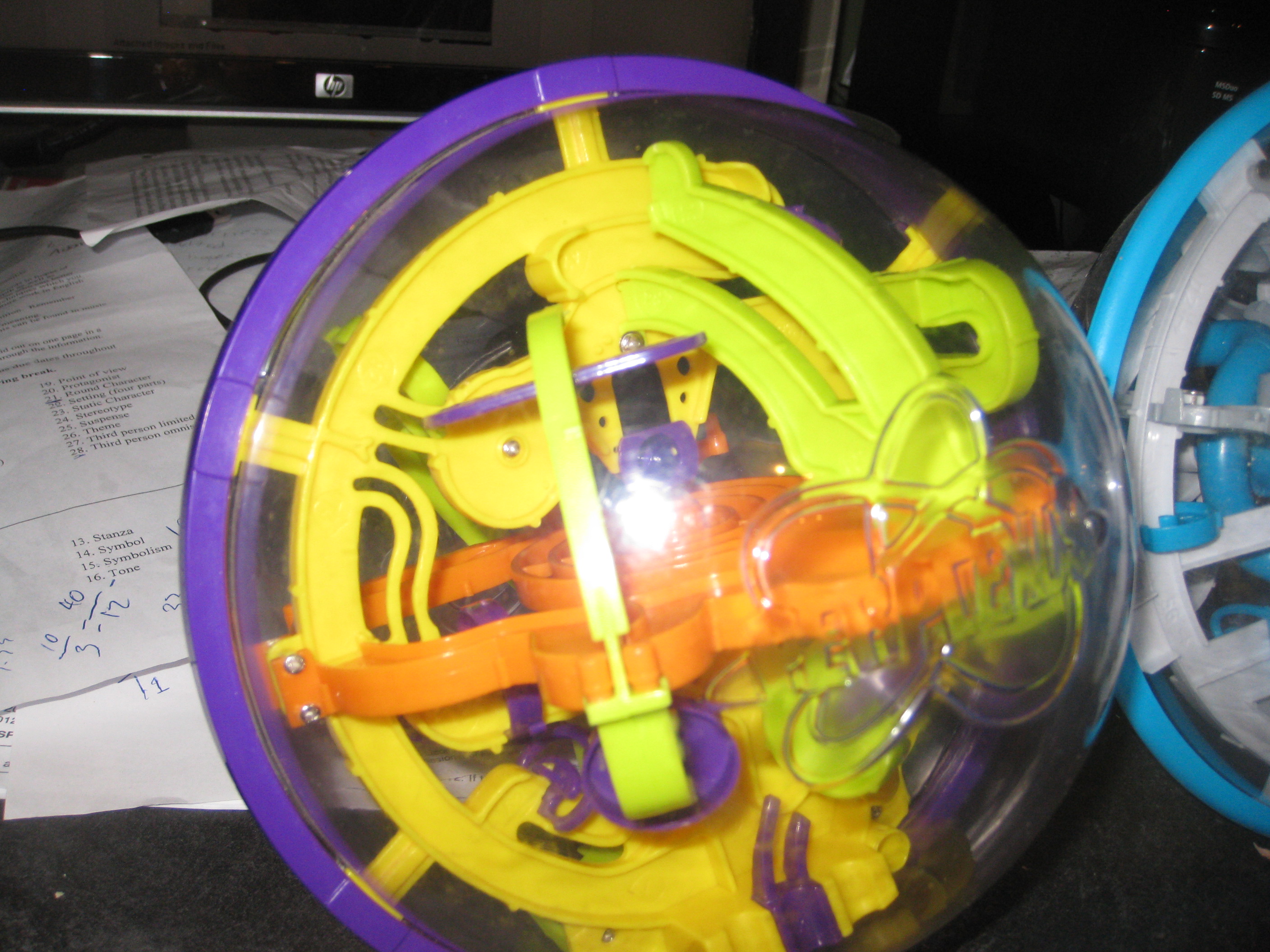
For those who don't know a Perplexus is a puzzle/game. It has a clear plastic sphere with a maze on the inside. The objective is to maneuver the marble through the maze without falling off the track. Ever since I first saw one I wondered how I could make my own, now thanks to Instructables free 3D Prints, I can.
I used Autodesk Inventor to create my own, and Instructables to print it off. Instead of a clear sphere I decided it would be much easier to make a cube out of clear acrylic, I found a relativity inexpensive piece at Home Depot.
This is a complicated design (at least for me) so rather than showing how to make each part, because allot of them are mostly the same just on a different axis, I will show the methods that I used to make them.
Thanks for reading, and if you could any votes comments or rating are much appreciated thank you-Lucas
Materials/Equipment

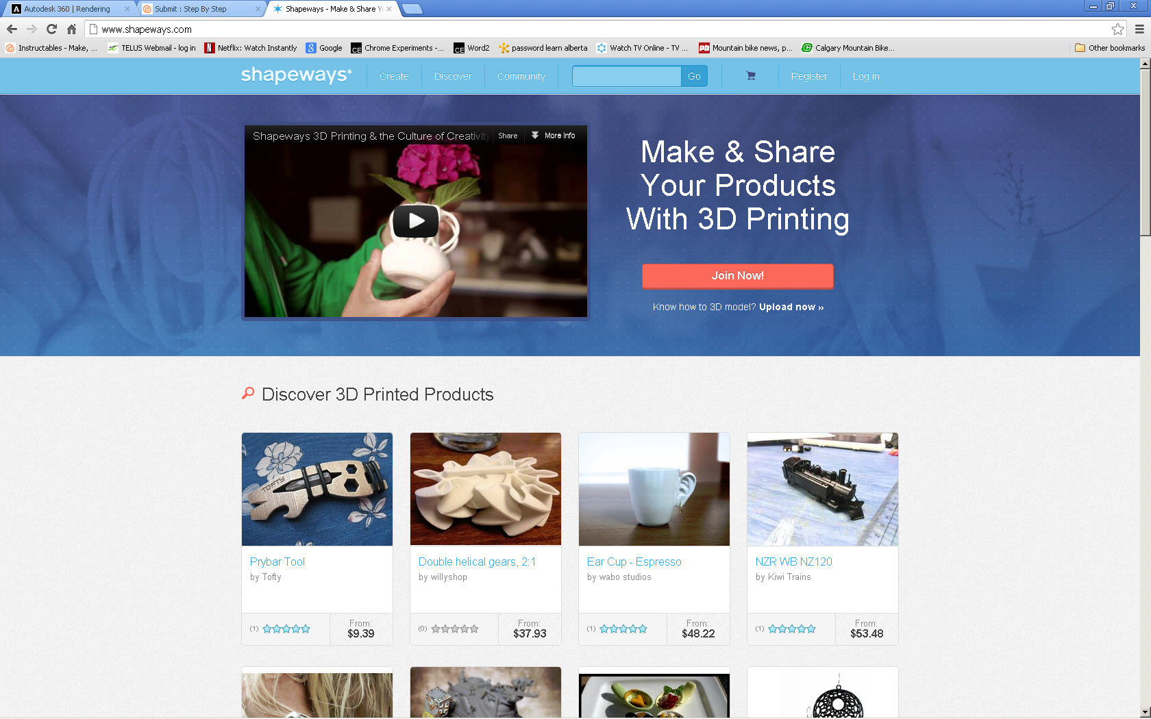
The things that you will need to make this:
3D Design software: I used Autodesk Inventor, so this tutorial will be based on that program However there are free alternatives that you can use as well. Google scketchup perhaps.
Access/Your own 3D Printer: Instructables has an amazing group you could join if your interested call "Free 3D Prints". Shapways and other online services will let you upload a larger object but it will cost you.
Clear acrylic sheet (or cube if you could find one) I found one at home depot
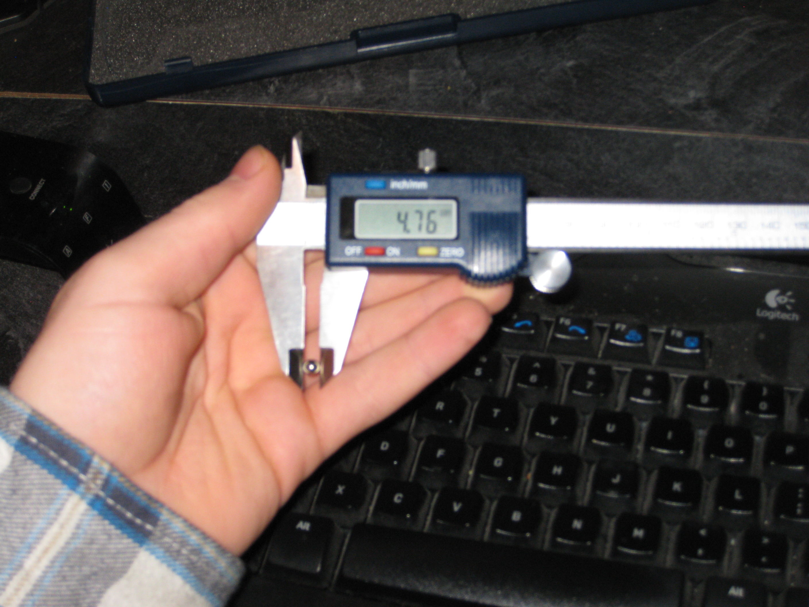
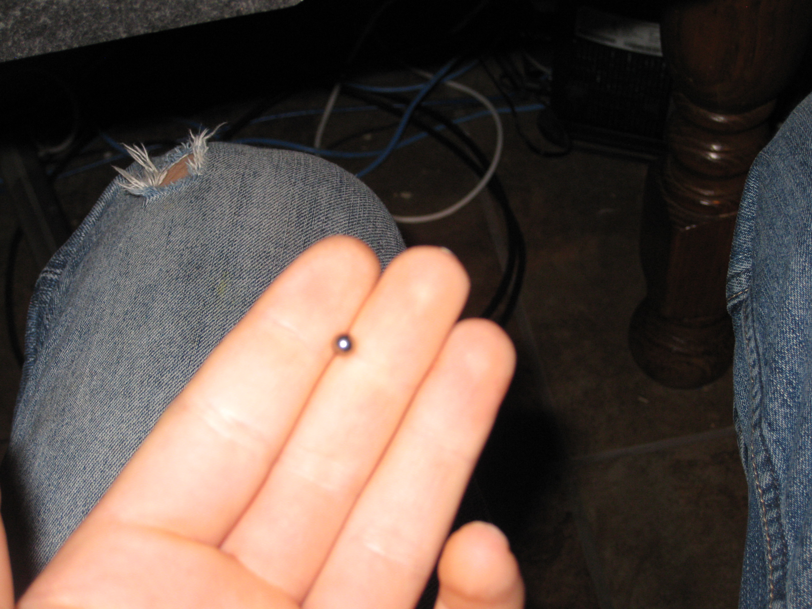
Small ball bearing or bead.
Saw to cut the acrylic with.
Glue and Tape to hold the cube together. Crazy glue and some clear tape for dry fitting.
Micrometer or ruler
Measure Ball Bearing

Use a Micrometer or ruler to measure the ball bearing or marble that you plan to use. Next find out how much space you have to work with. This will vary on how you are going to print this off, in the case of an instructables Free print you get a 3" (inch) bounding box.
Launch Inventor
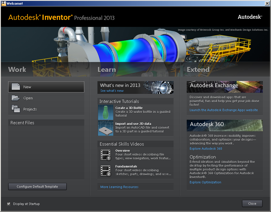
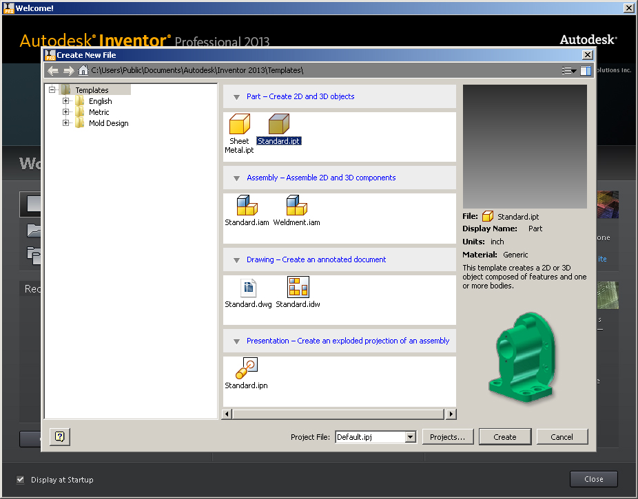
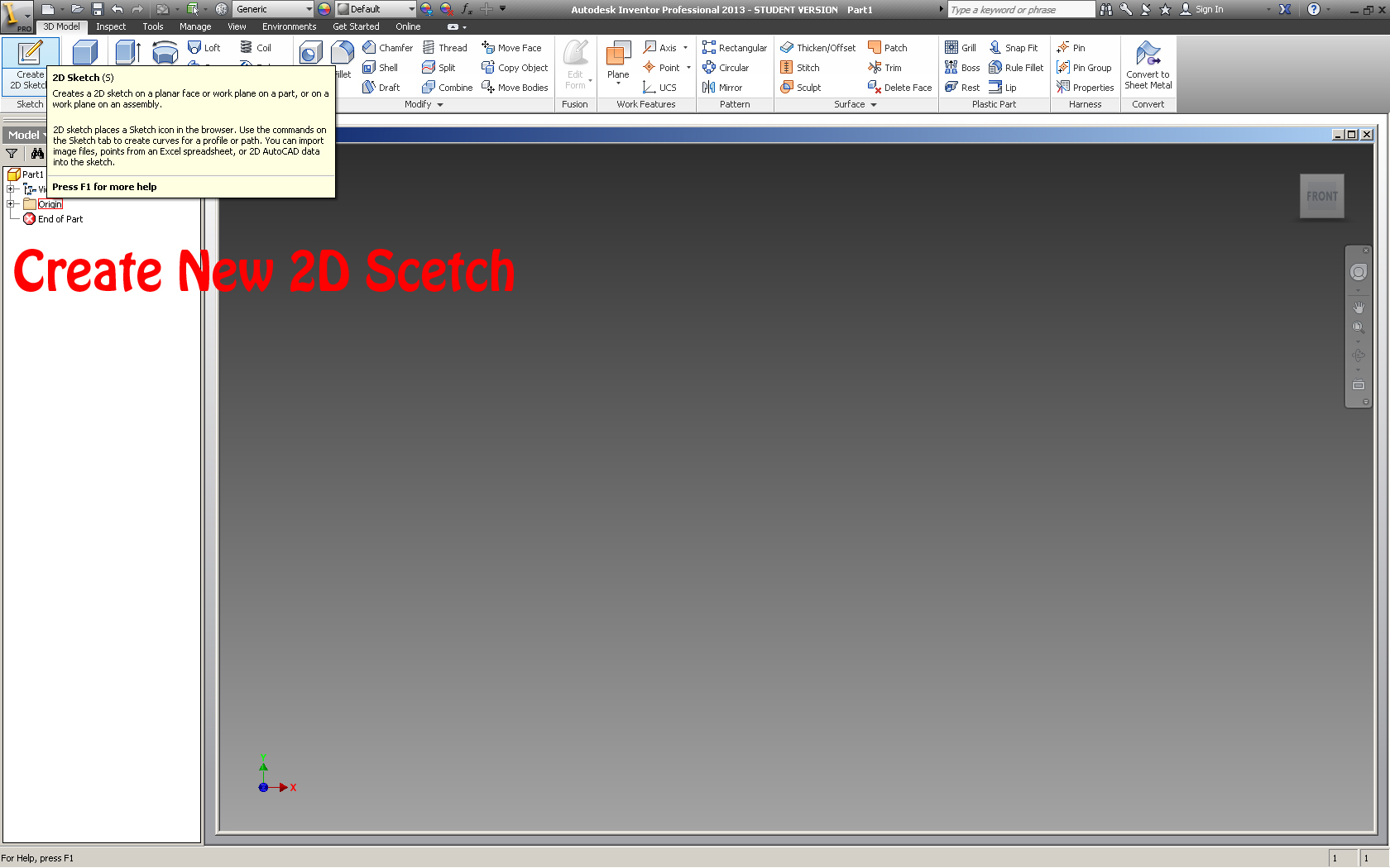
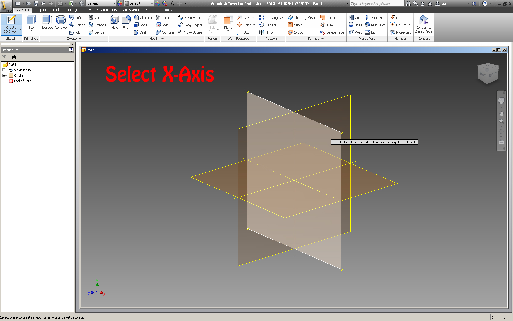
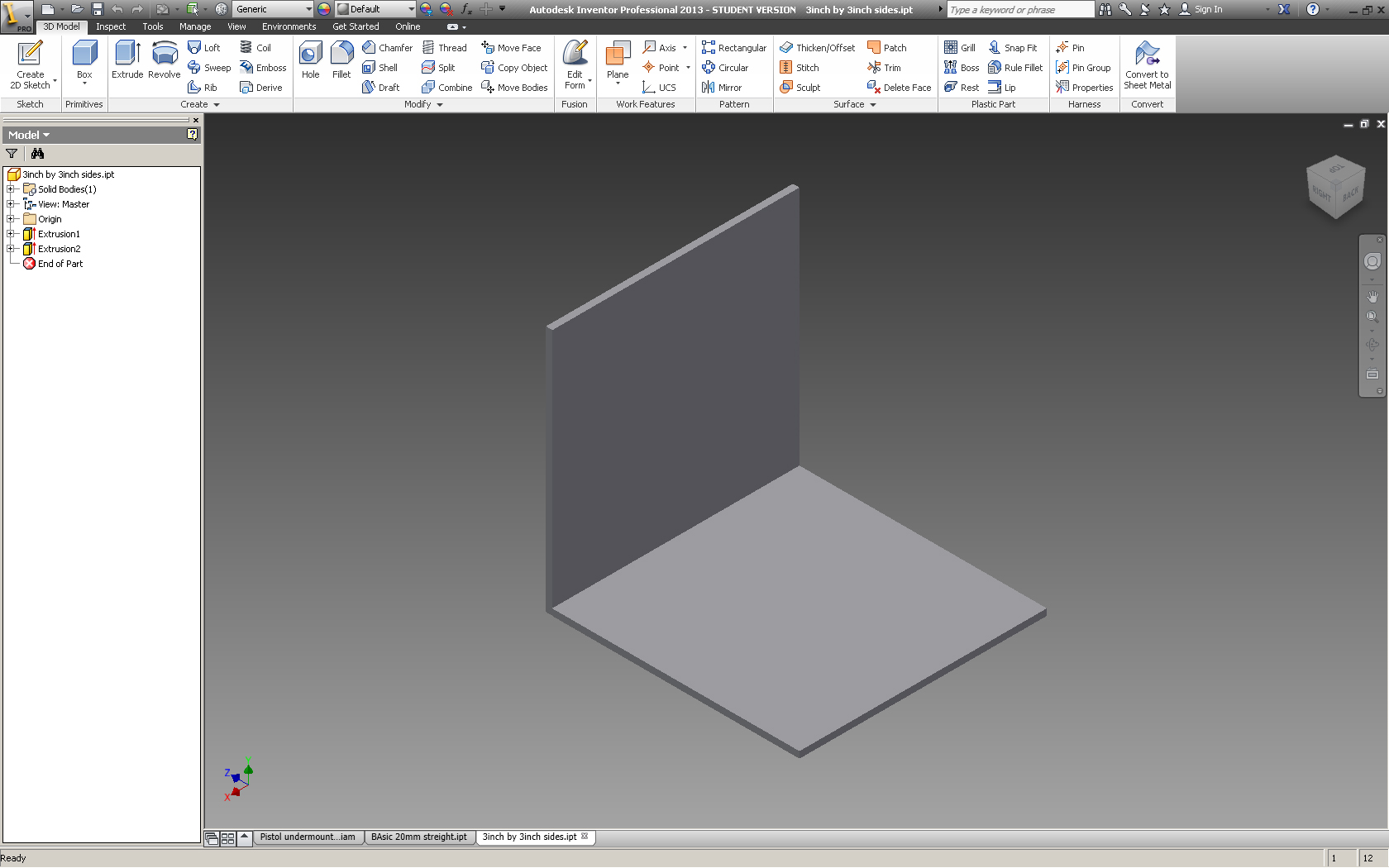
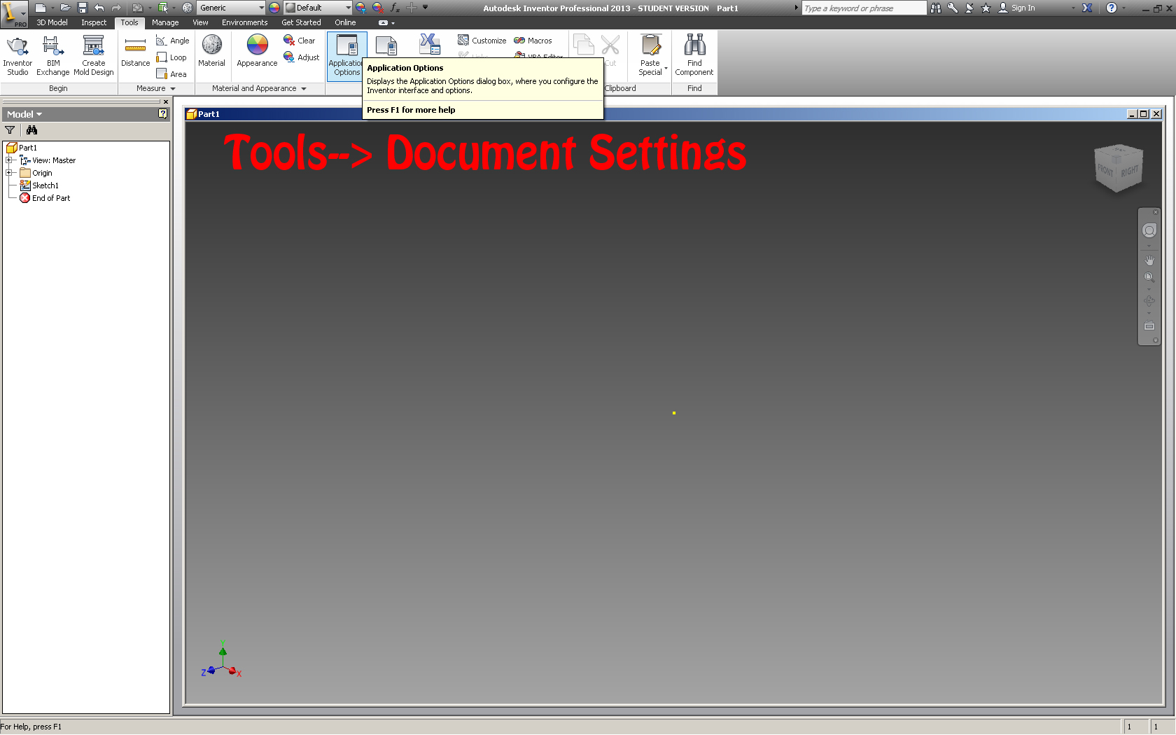
Open up Inventor (or the design software you choose to use). Now there are multiple ways to create this model.
If you have a well planed design then you can draw each part separately, or you can create an assembly and build the separate pieces onto the existing pieces.
I found that creating the parts inside the assembly to be easier, however both have advantages and disadvantages. One disadvantage of using the method I did was that it was difficult to take pictures of each of the parts without other parts being in the way.
Either way the first step is to open up a new .ipt (part) file. I choose to work in millimeters however you can change the units by either opening up a new standard mm .ipt or a standard (in) .ipt. The units can also be changed later in tools--> Document Settings--Units.
Once the part is made save it in a location you will remember.
Next if you are using the draw in assembly method create 2 boxes that are the same size as you want the print to be (in my case 3" or 76 mm) that are 90º to each other.
To draw parts in inventor you have to create a new 2D Sketch, then select a plane to draw on (ex. XY,YZ,XZ) then draw the part. After you can either extrude it to give it it's third dimension or use some other methods (Described later). In this case extrude it to the thickness of the acrylic sheet you plan to use.
Open Assembly
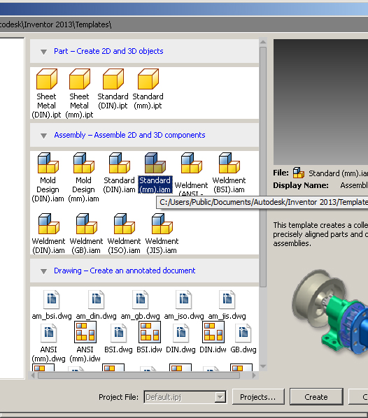
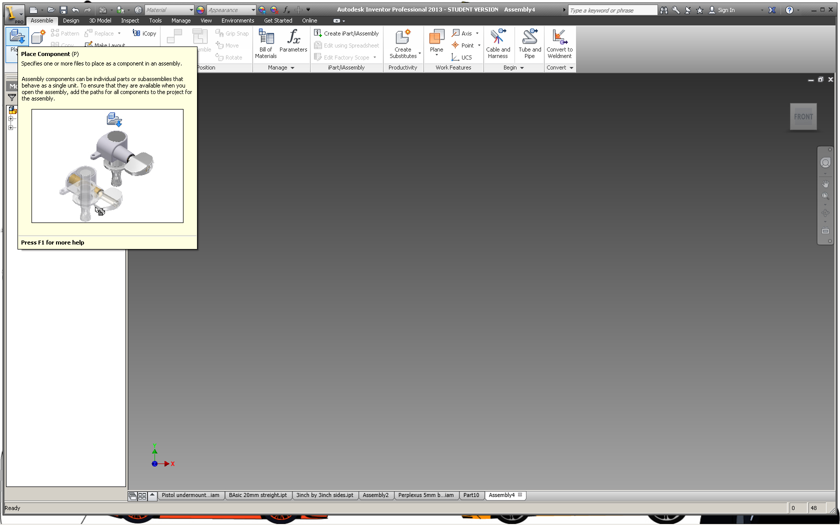
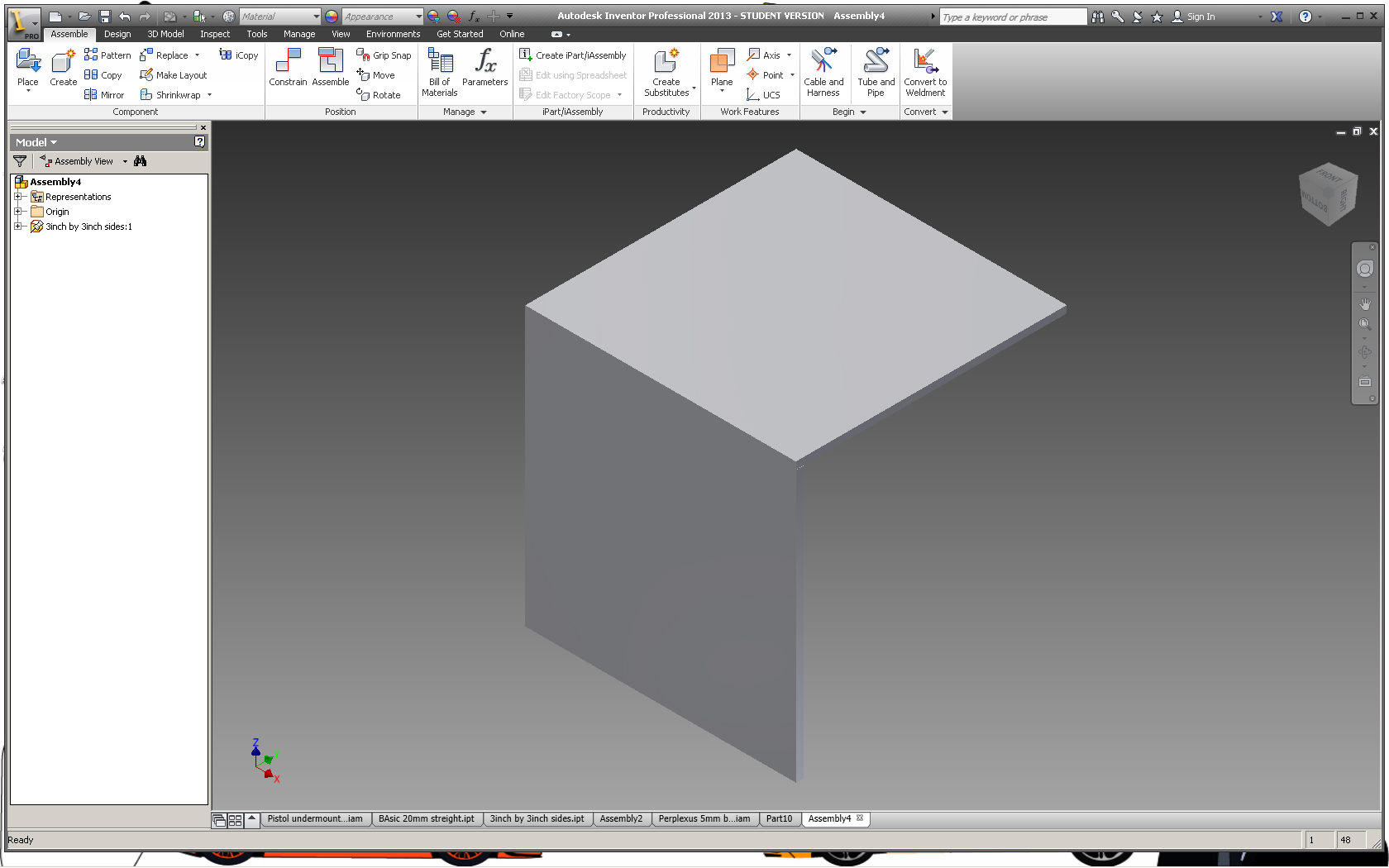
Open up a new assembly (.iam) file and place the 2 sided box in it. The place component button is in the top left corner. Make sure you don't select the little arrow beside it otherwise you might not be able to find your 2 sided box.
The Starting "V"
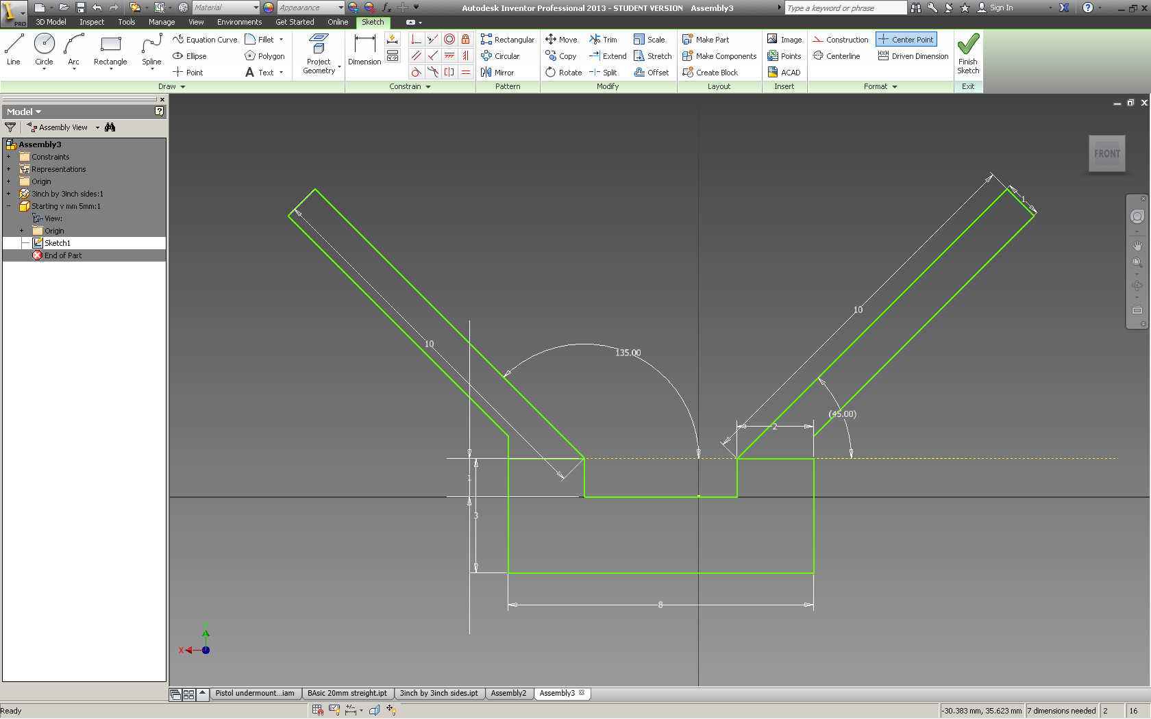
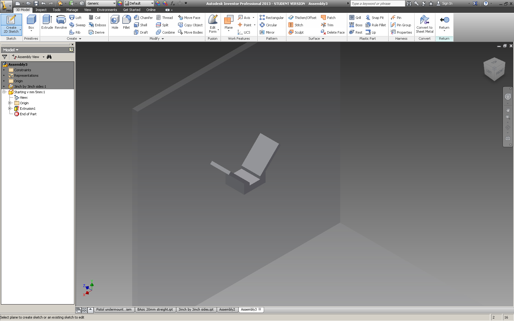
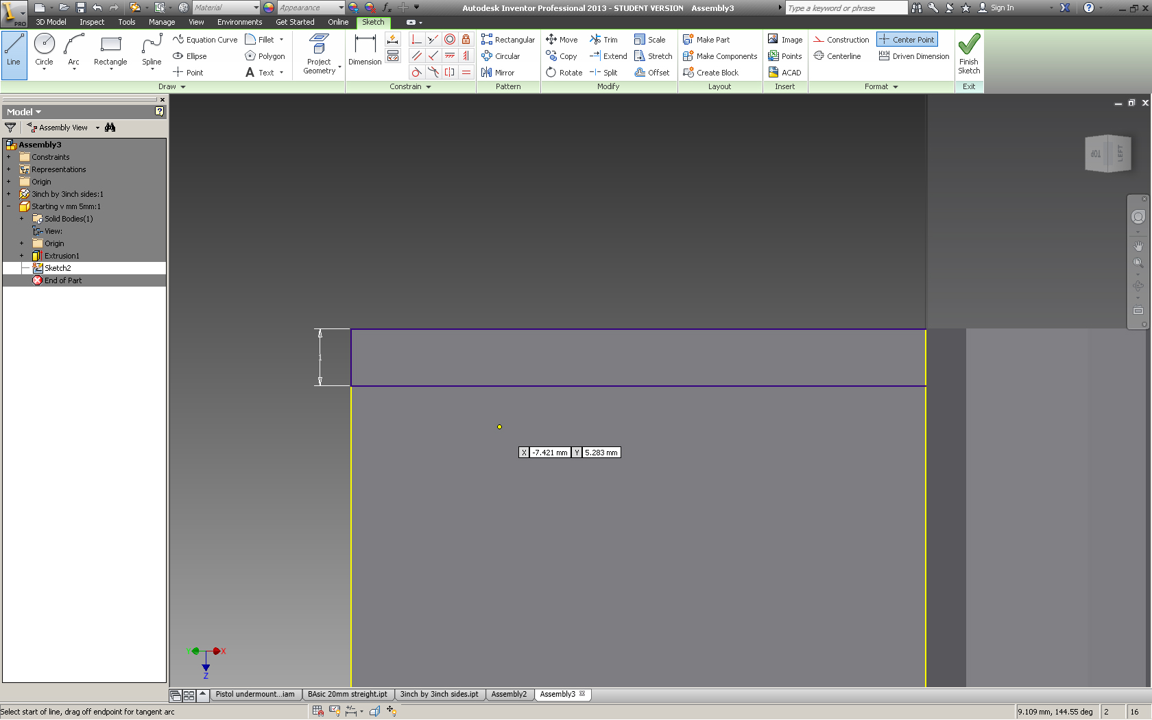
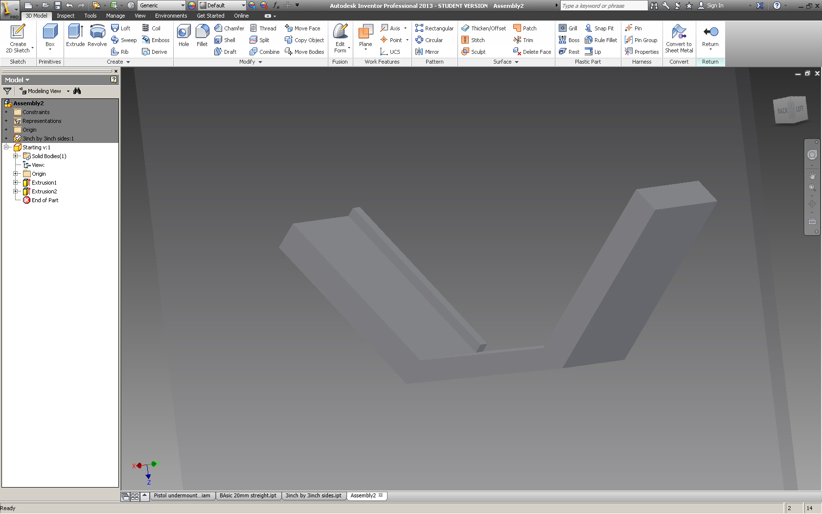
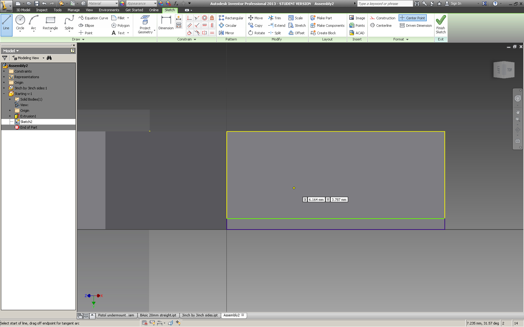
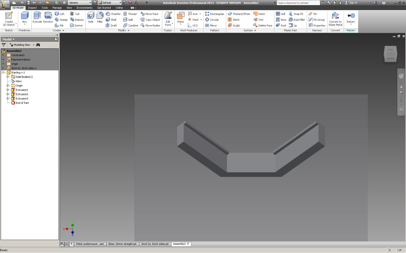
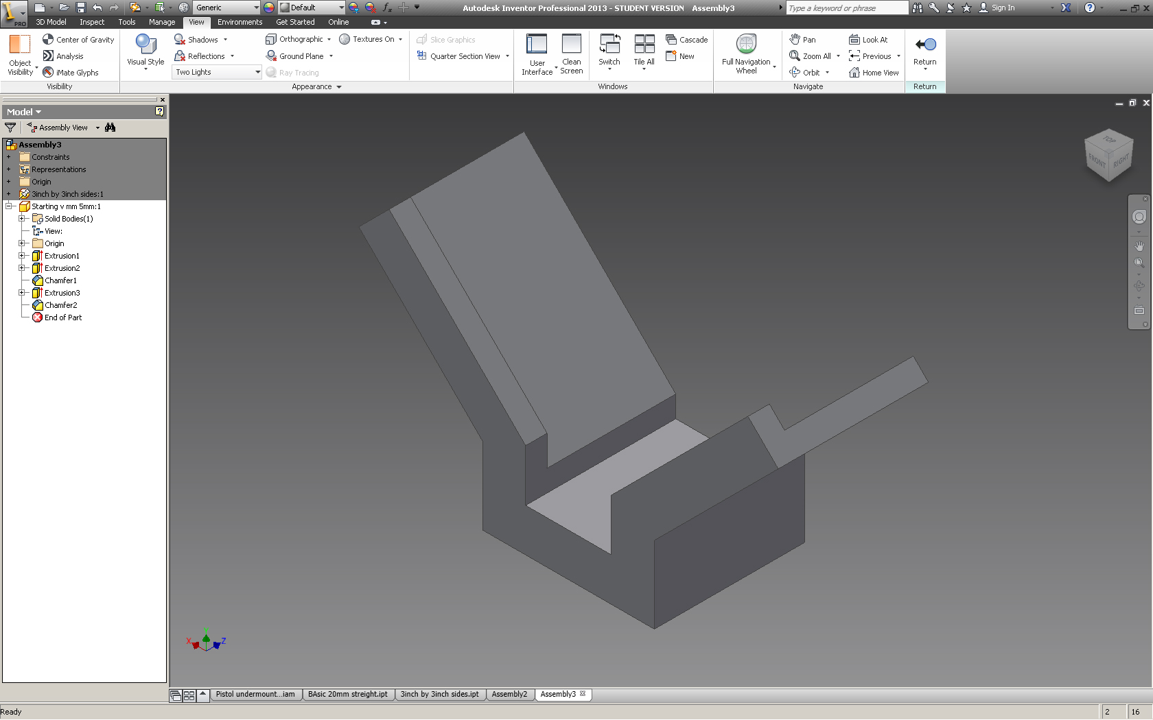
One of the problems I have with the current perplexi is that it takes a few tries to get onto the starting place. I tried to make this easier by making a V shaped structure that would funnel the ball onto the starting block.
Create a new 2D Sketch and select one of the inside faces of the 2 sided cube. Next draw out the V with dimensions that will fit your ball. then extrude to about 2 mm wider than the ball. 1 mm for clearance and 1mm for a small wall that stops it from falling off.
Next create a new 2D sketch on one arm of the "V" make it 1mm wide and the same length as the arm of the "V"
Extrude that sketch so that it is about 2mm tall, you can vary the height of the wall to adjust the difficulty of the starting peice.
Reapeat on other side of V
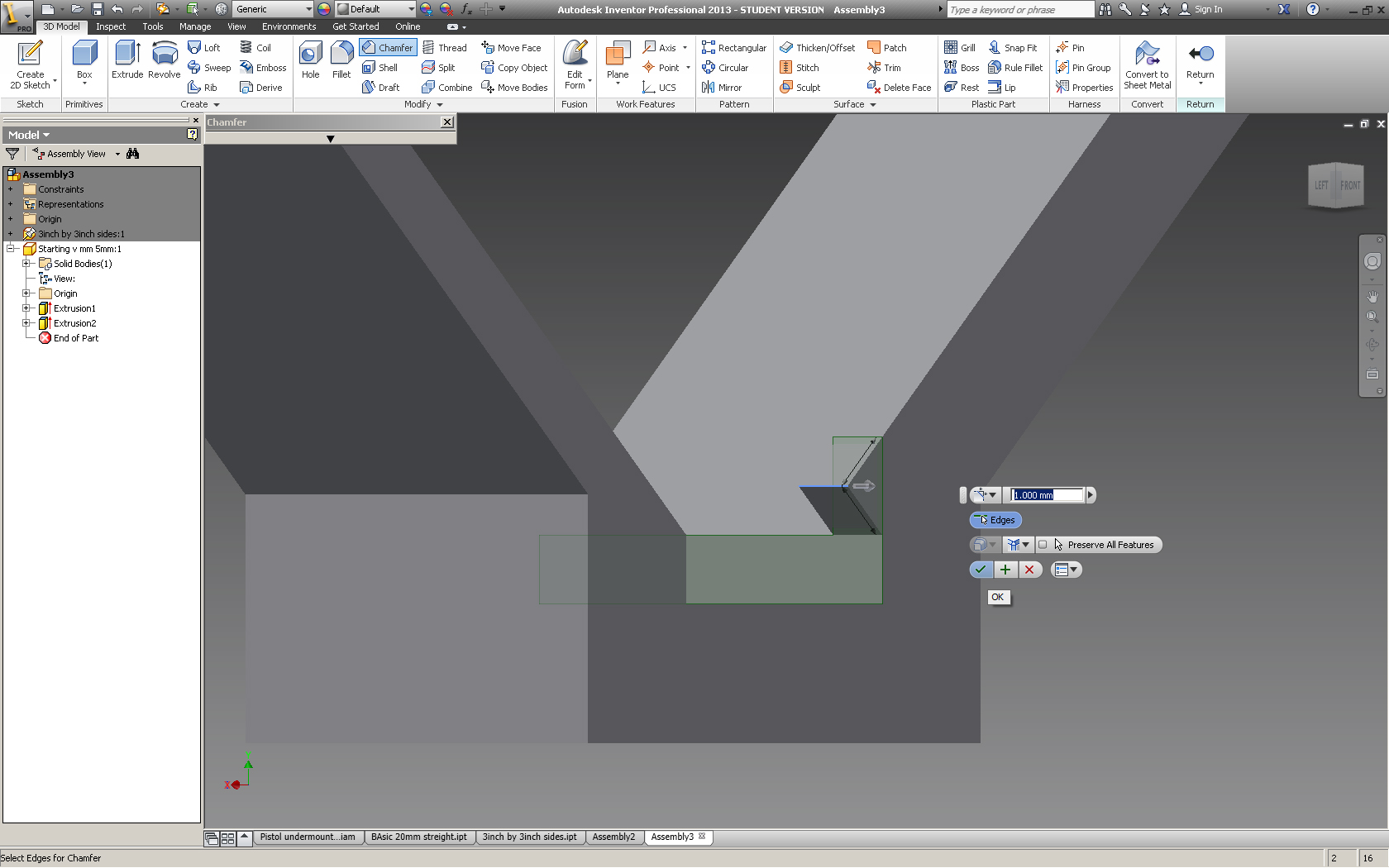
Now you may have noticed that the walls have made it so that the ball will no longer fit between the arms of the V
Chamfer the offending edge by 1mm (or the height of the wall)
If this isn't clear please refer to the pictures.
Basic Straight
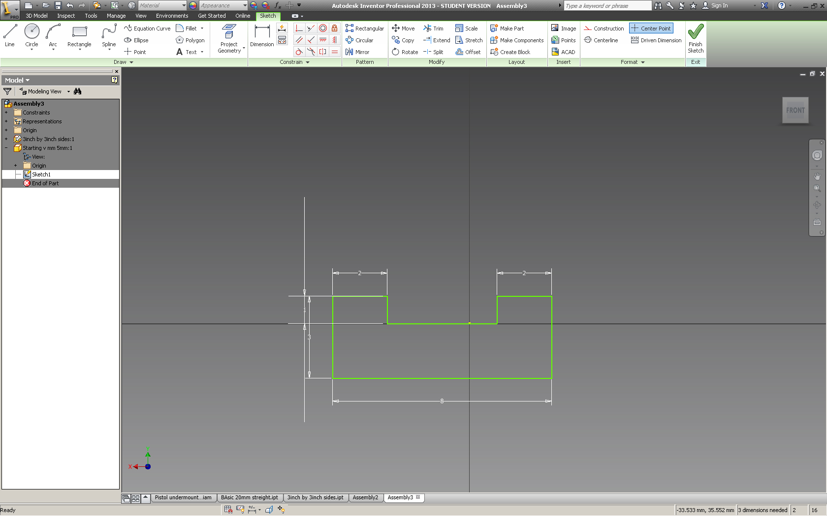
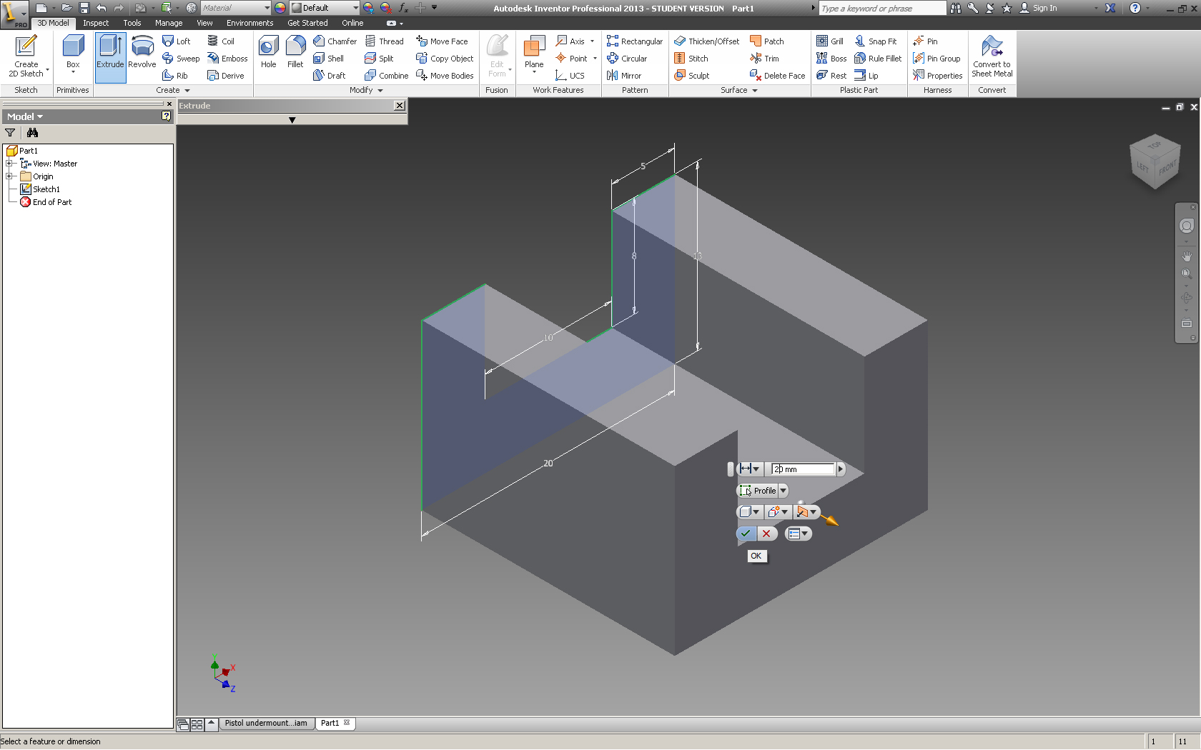
This is the basis of all the other parts (except for the Starting V) It is a trough that the ball bearing will roll along. It is 8 mm wide at the bottom, 6 mm wide at the top and has 2 1 mm thick sidewalls. The height of the side walls varies to increase/decrees difficulty based on how the part is extruded.
Create a new 2D sketch and select the end of the starting V (the face that is on the same axis as the 2 sided cube, but not touching it.
Then draw the sketch with the given dimensions or change them to suit your needs. Extrude this piece about 10 mm.
Create a new 2D sketch and select the end of the starting V (the face that is on the same axis as the 2 sided cube, but not touching it.
Then draw the sketch with the given dimensions or change them to suit your needs. Extrude this piece about 10 mm.
Curves and the Sweep Command
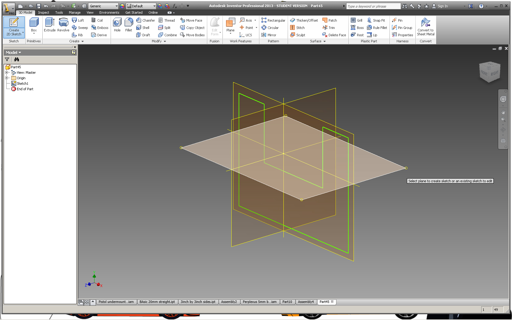
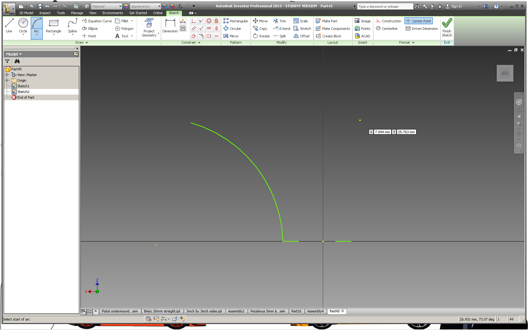
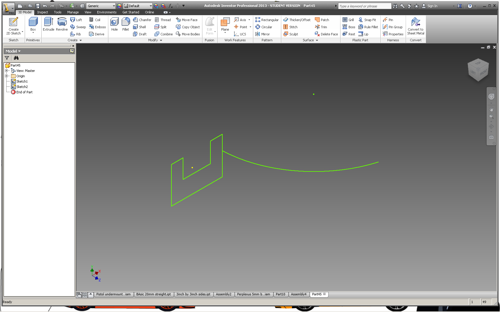
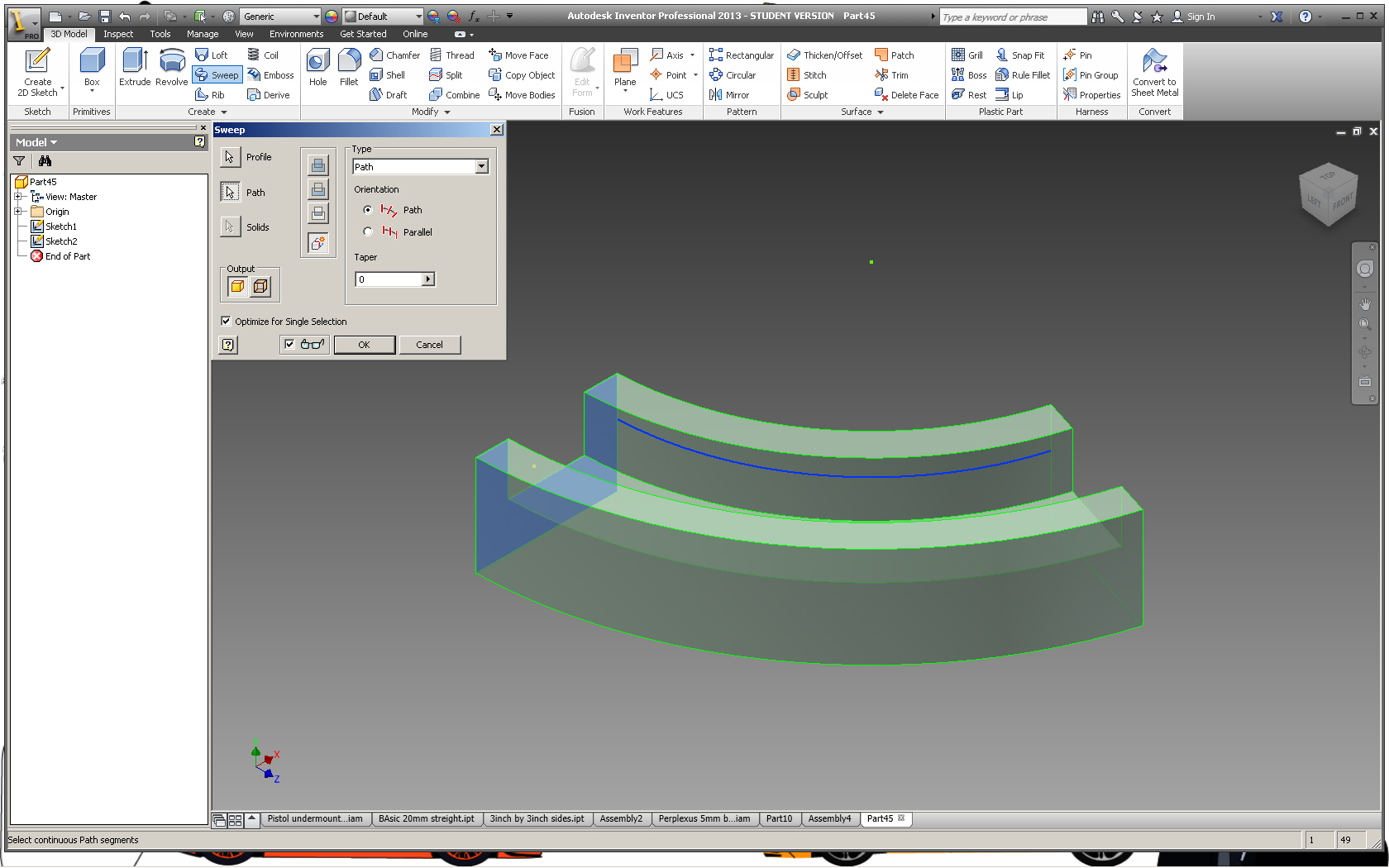
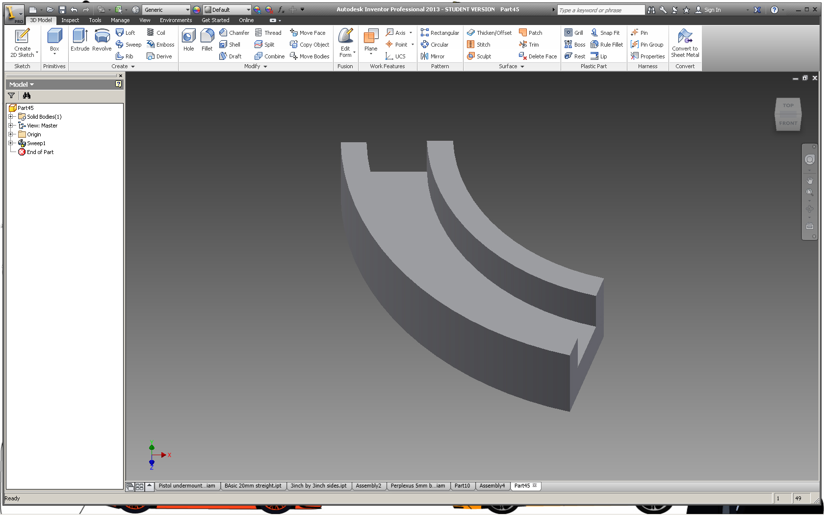
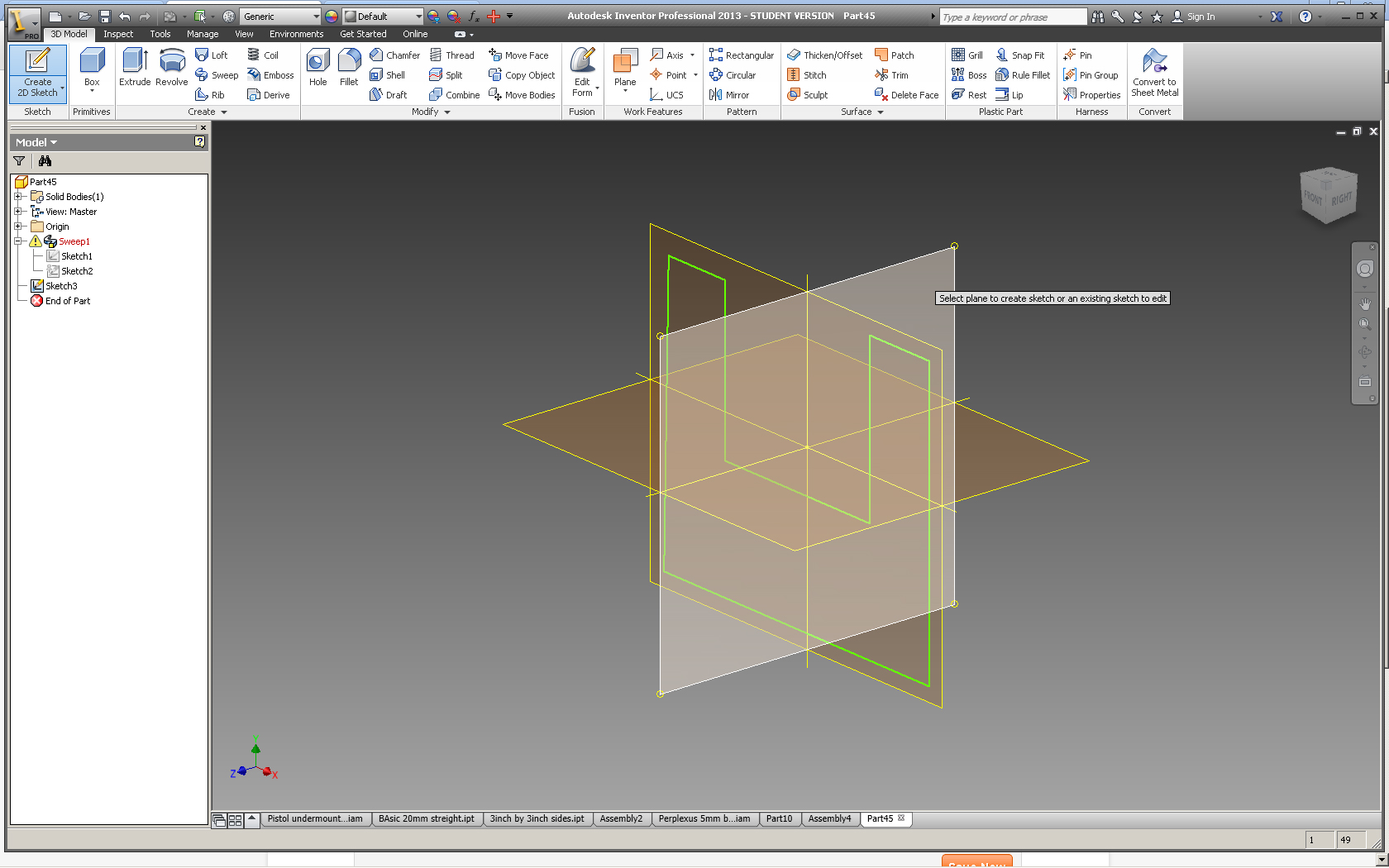
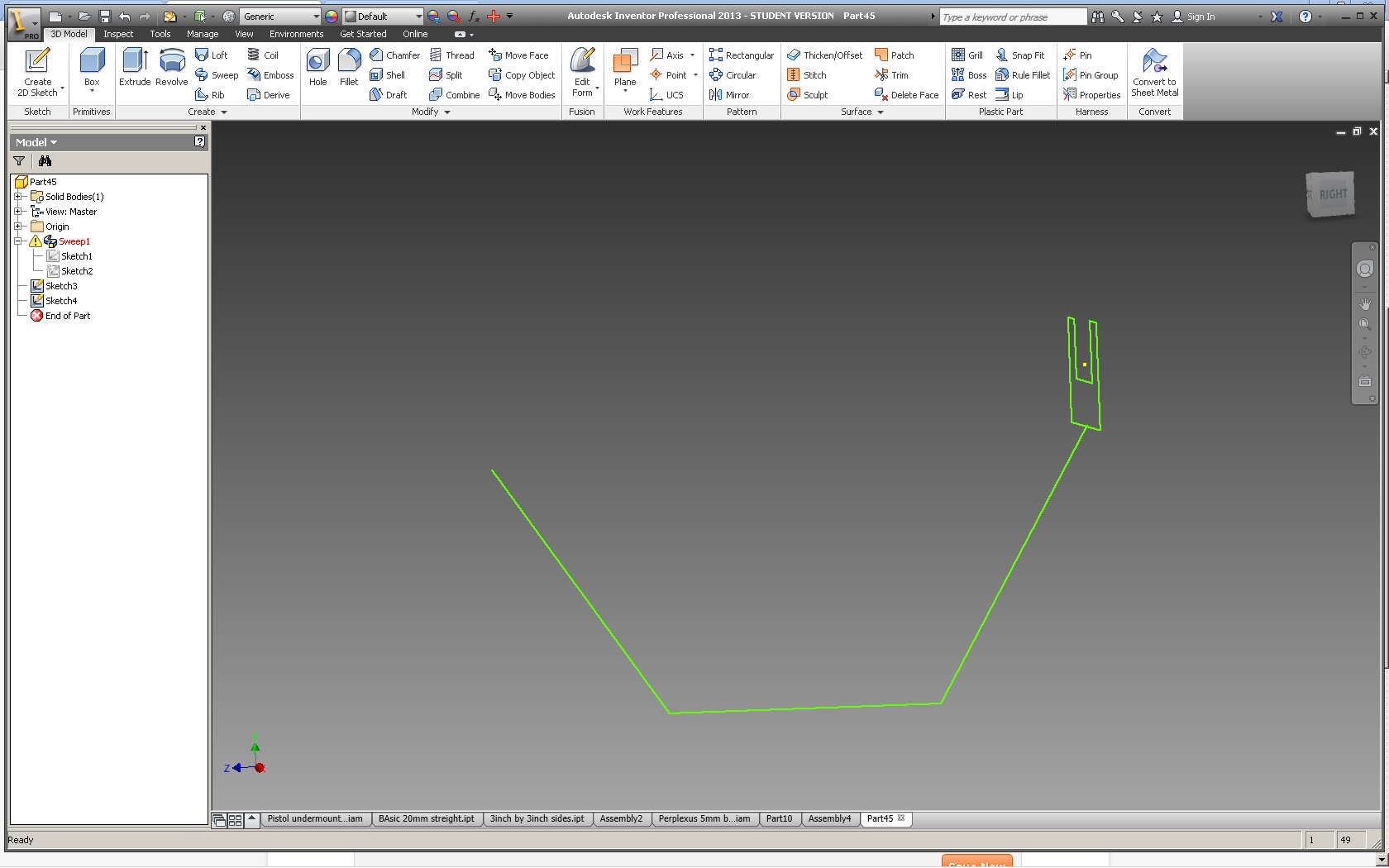
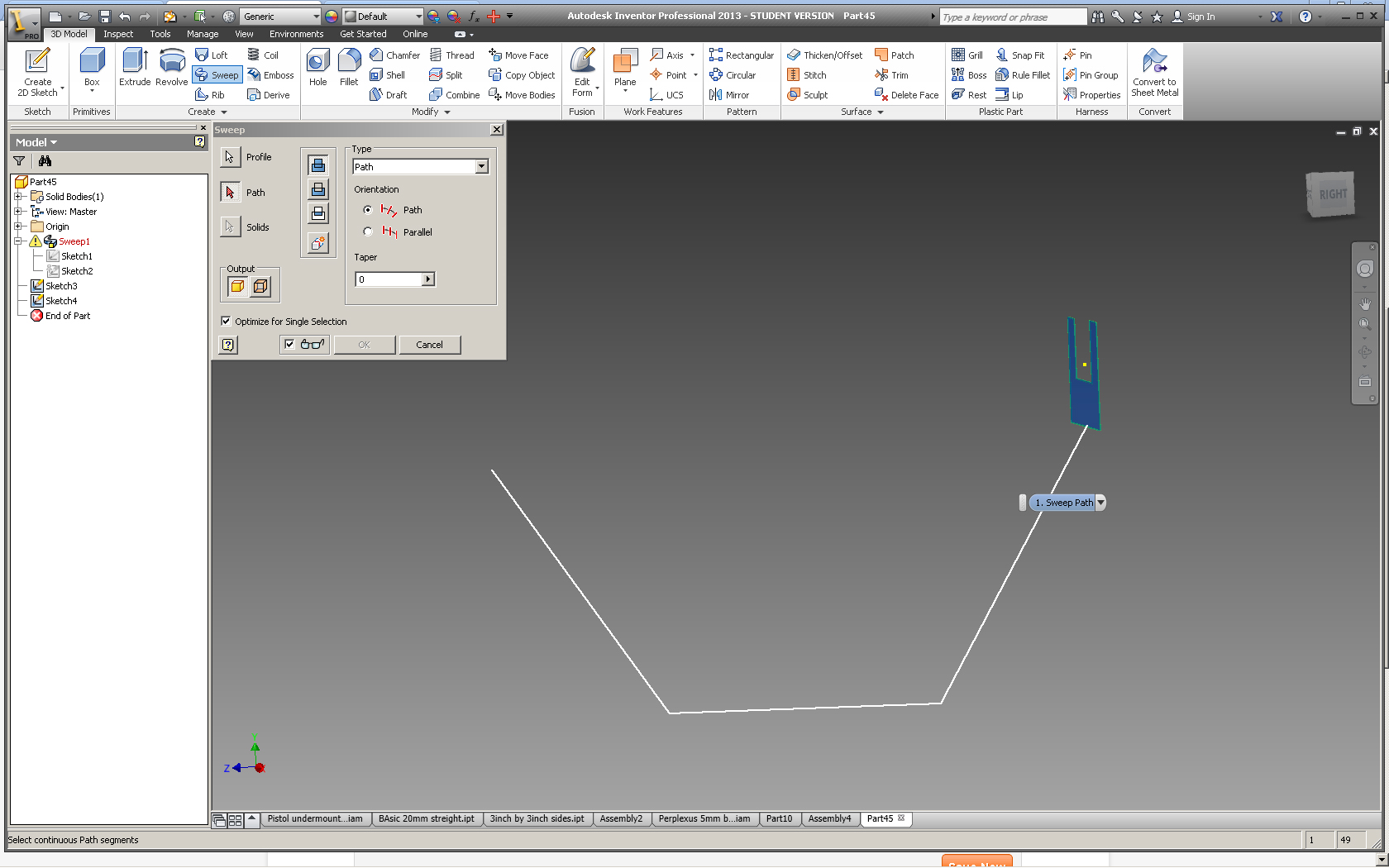
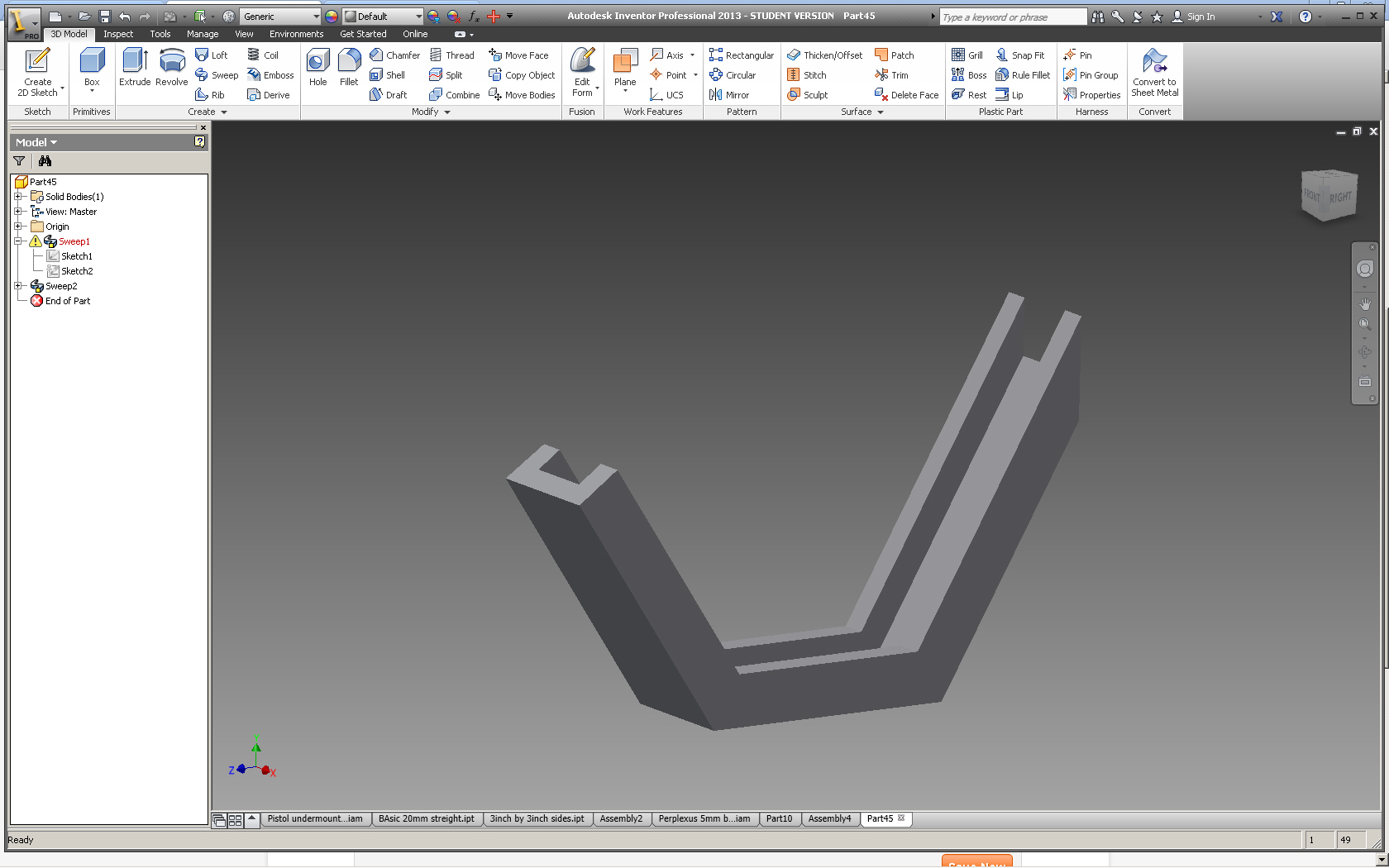
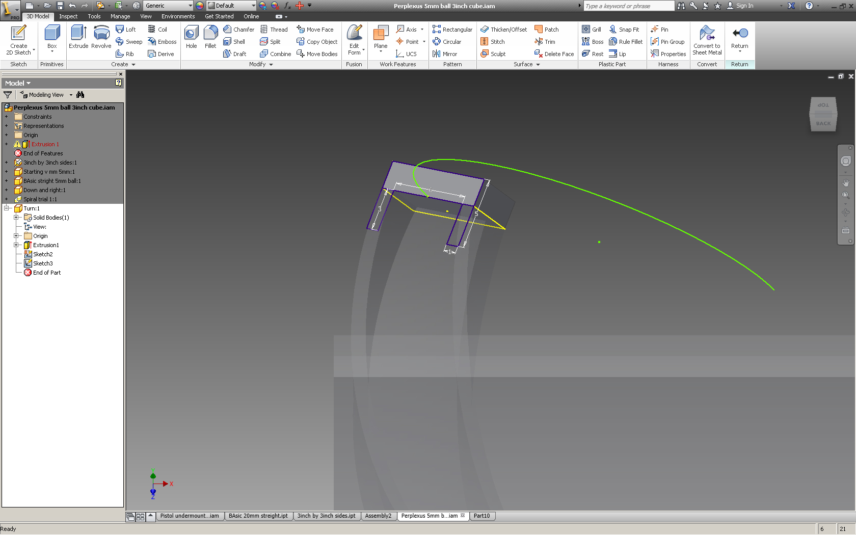
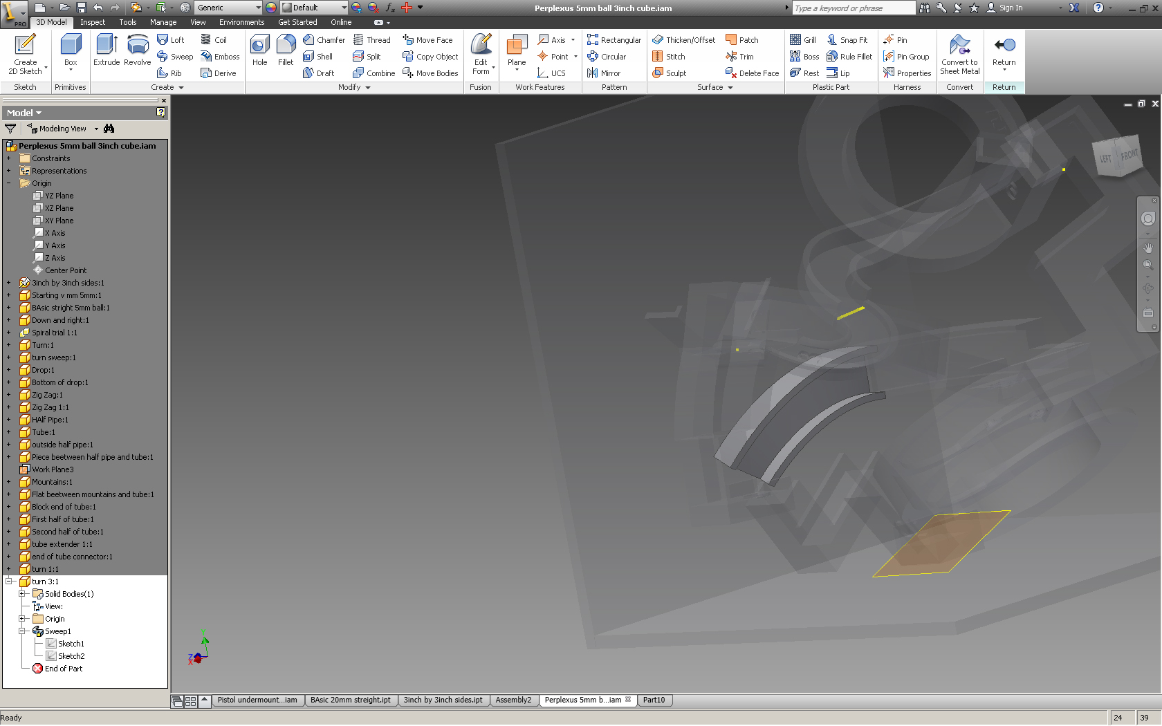
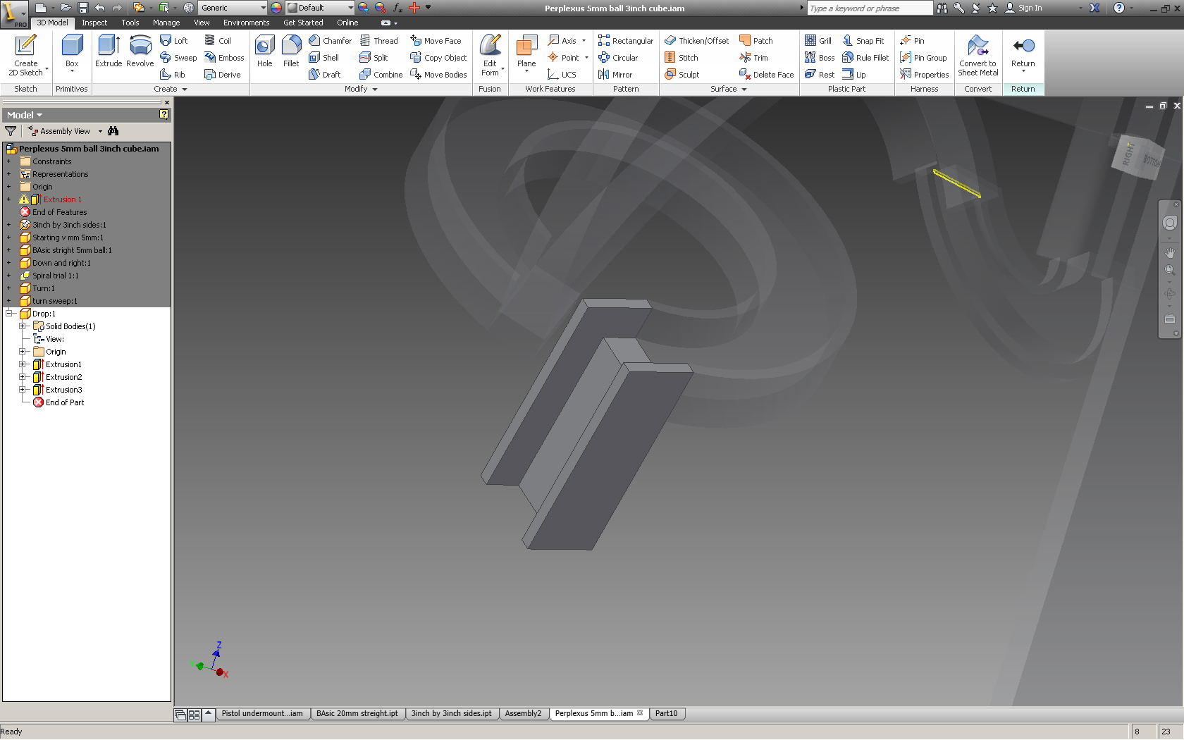
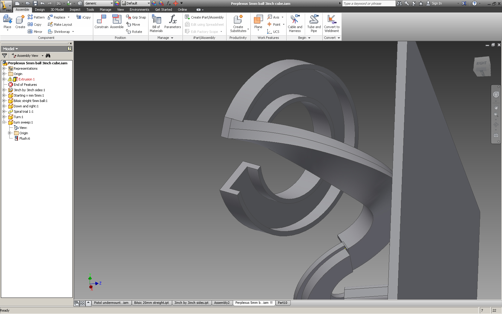
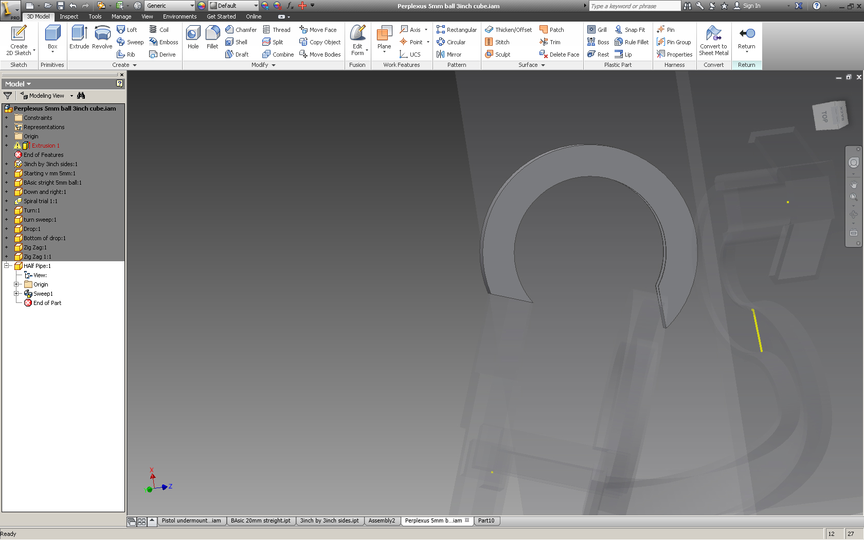
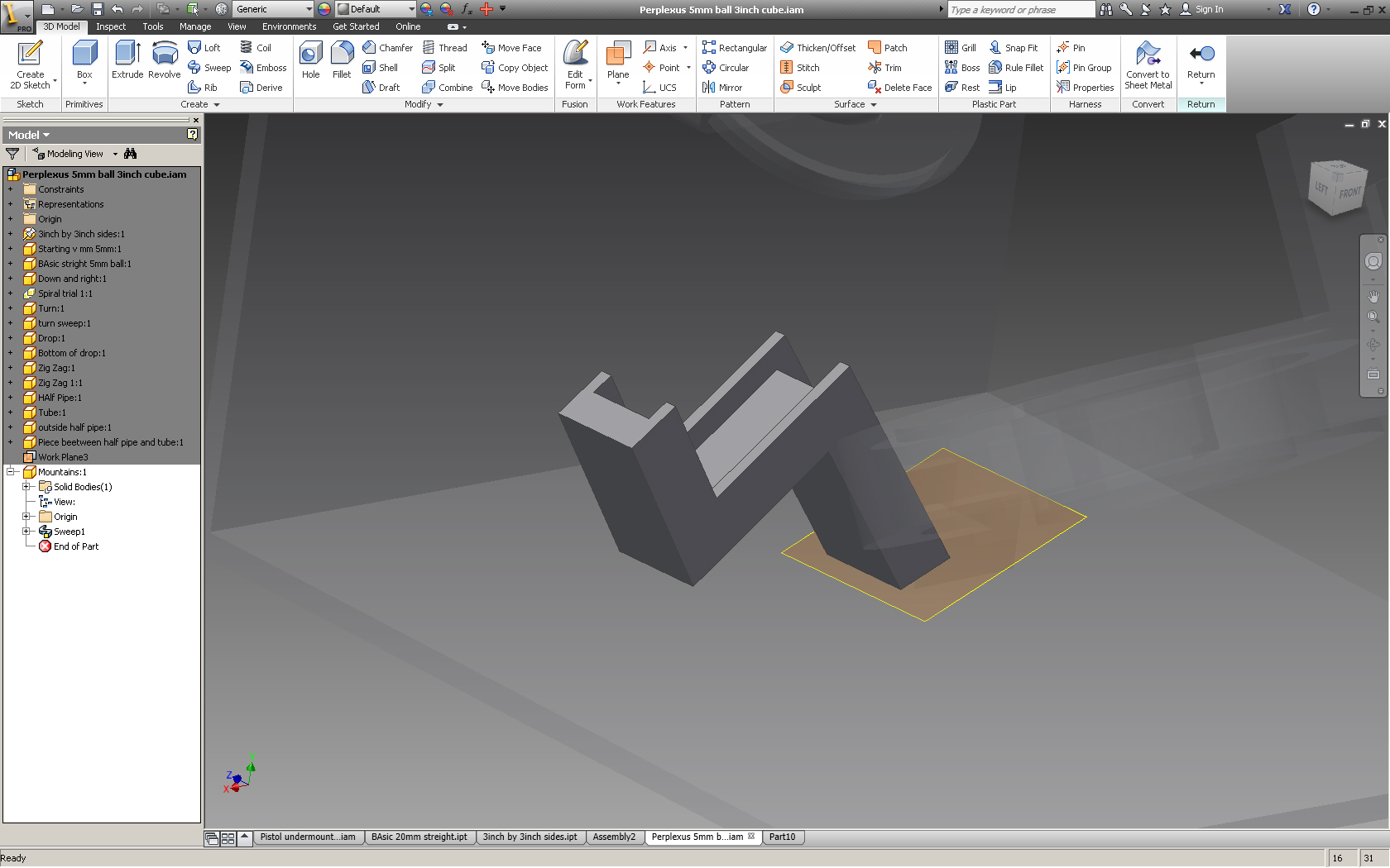
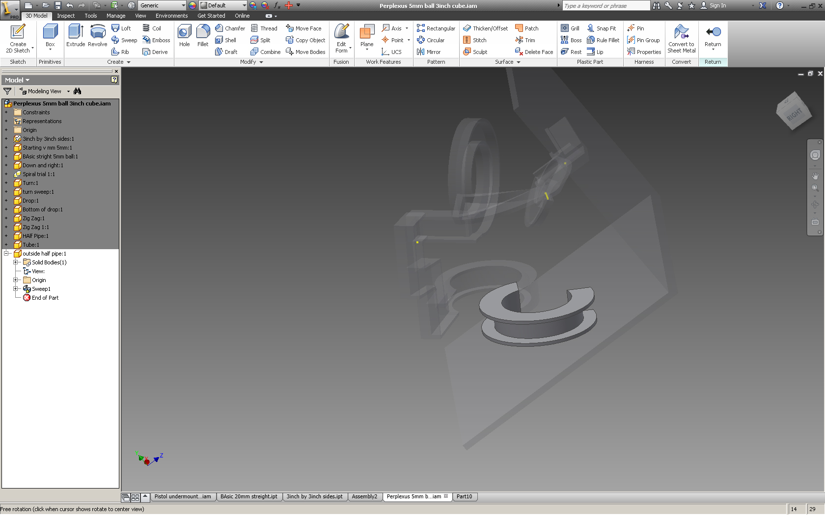
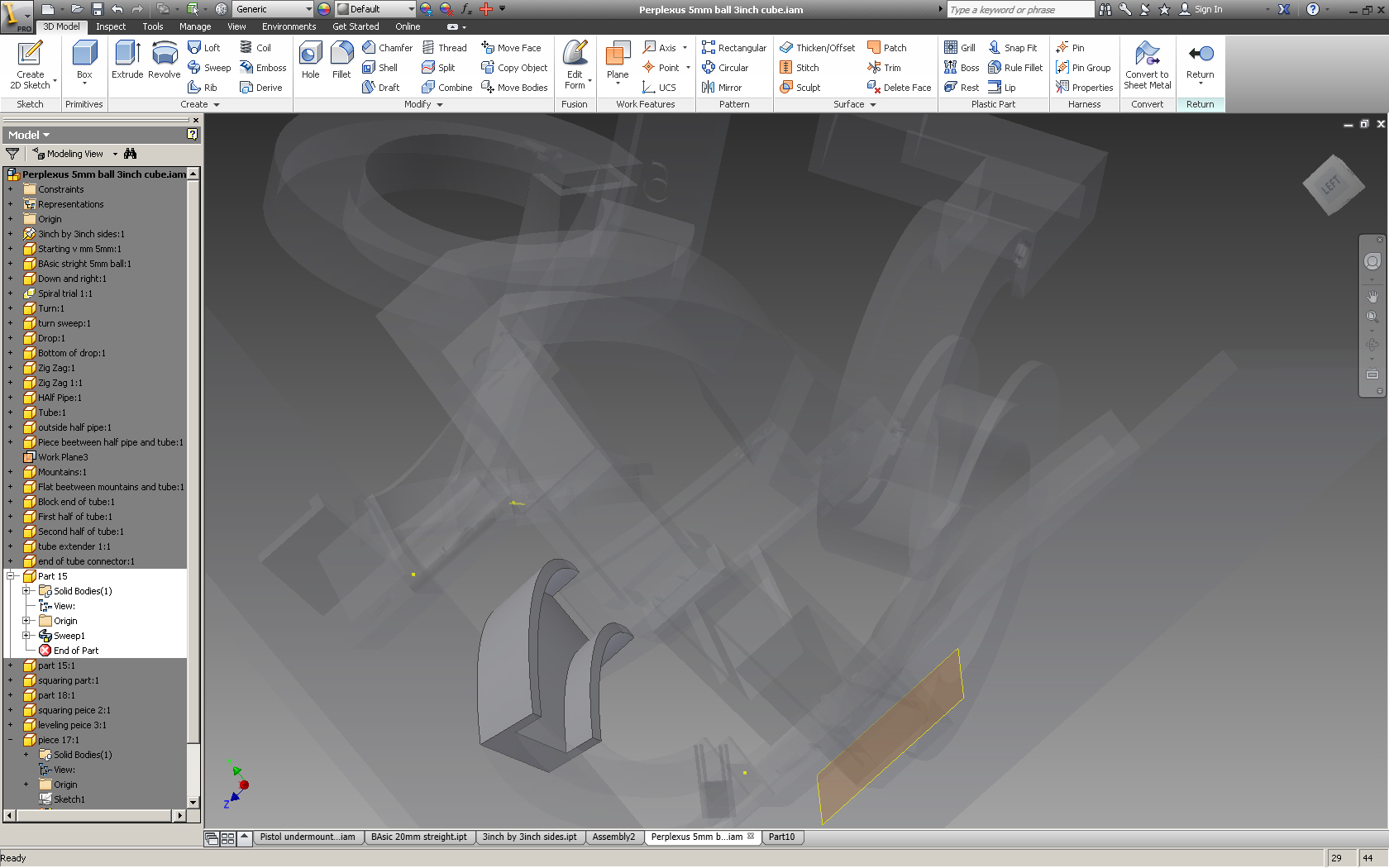
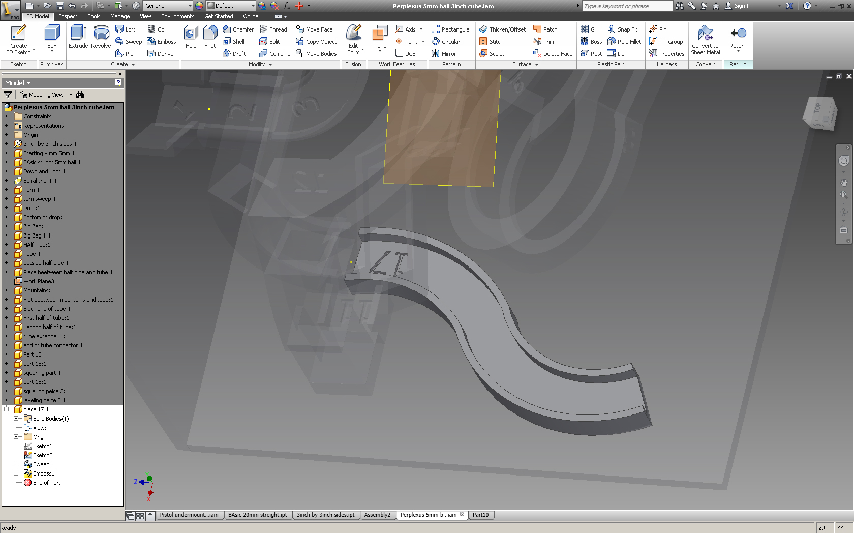
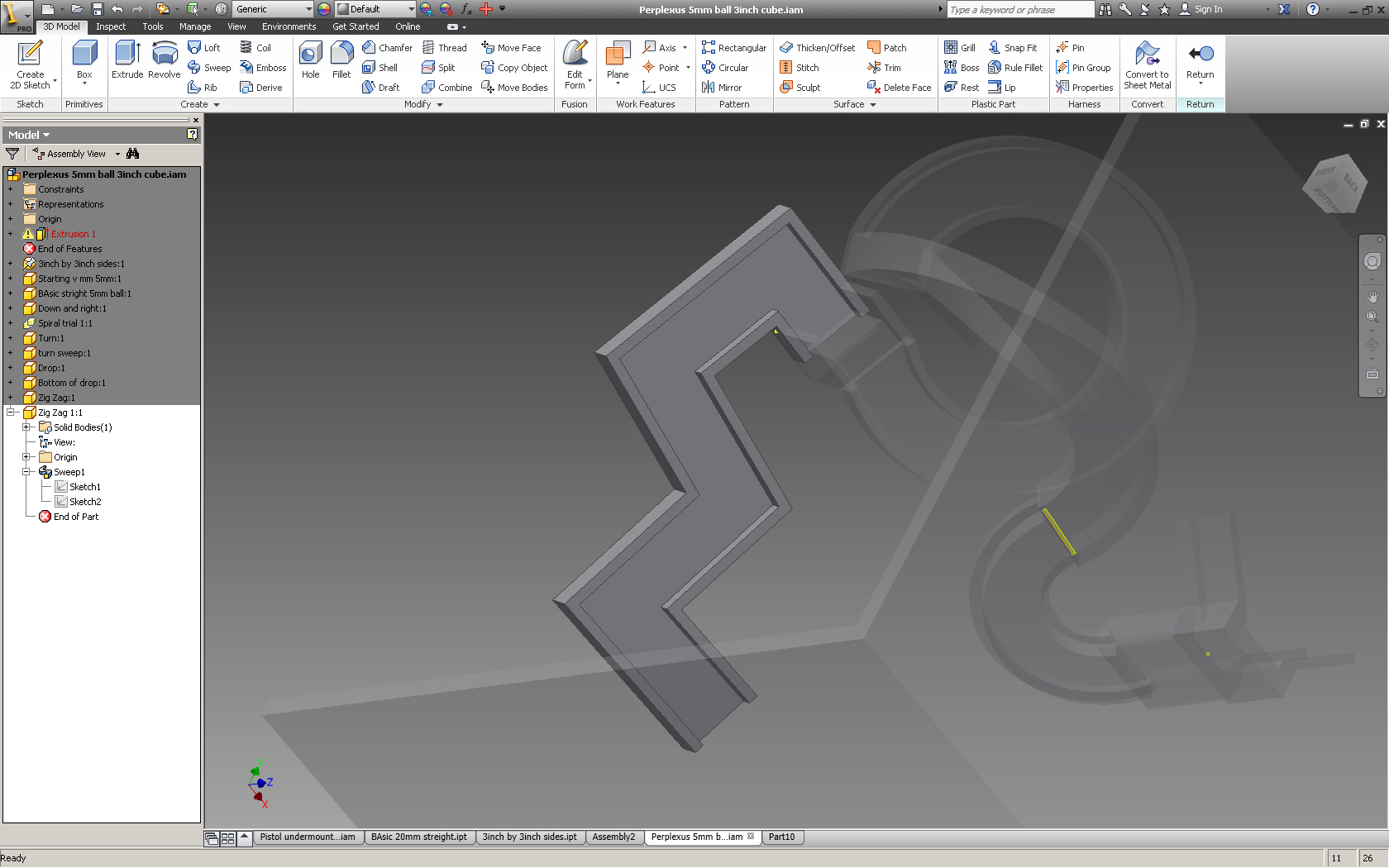
Obviously the puzzle would be rather boring if all the paths went in straight lines. To give them curves I used the Sweep command.
To create a curved piece start with a 2D sketch and select the plane to draw on. Use the same plane as if you would be creating a basic part and then extruding it.
Once the basic sketch is there create another 2D sketch except this time select the plane were you are looking down on the basic 2D sketch. Then draw a curvy line that starts at one corner of the basic 2D sketch and ends were you want the piece to end.
Finish this sketch, now select the sweep command, the box will pop up asking you to select the profile, select the face of the 2D basic sketch, then selct path and click on the line that you just drew. It should sweep the basic part sketch along the path of the line you just drew creating a curved pathway.
If you want to curve the piece "up" select the other axis when you draw your path.
The last set of pictures are parts of my "Perplexus" that used the sweep method for creation. This is the major command I used when creating my object.
Spirals and the Coil Command
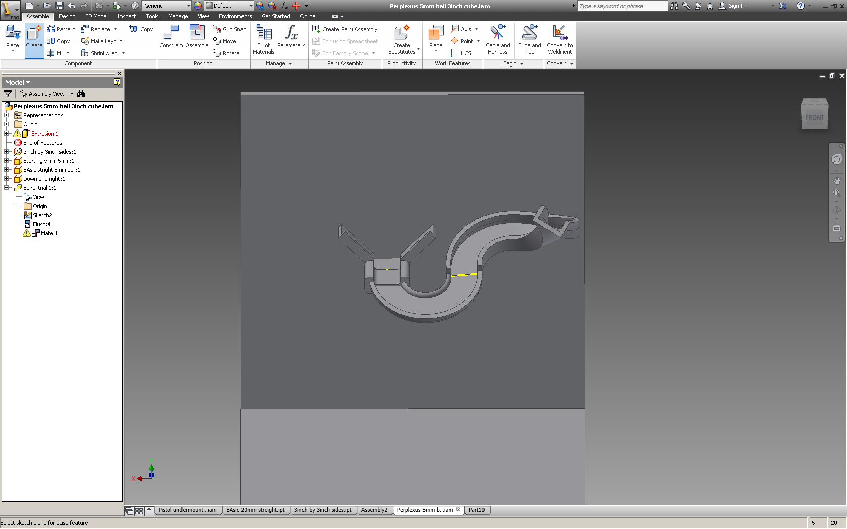
This is how to make a spiraling pathway. The coil command much like the sweep command needs two drawings one of the profile and one for the center of the rotation. The distance that the second line is away from the profile will determine the radius of the spiral. In the box that pops up there are a number of parameters that can be changed to achieve the desired result. I found that this required allot of trial and error, but maybe that's just me. I found this video that shows quickly how to make a spiral. Follow the same steps but instead of using a circle use the basic 2D sketch that was in step 6.
Tunnels and Tubes
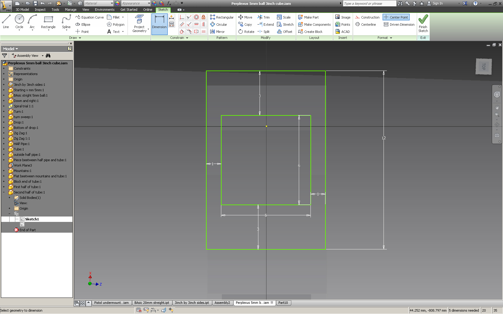
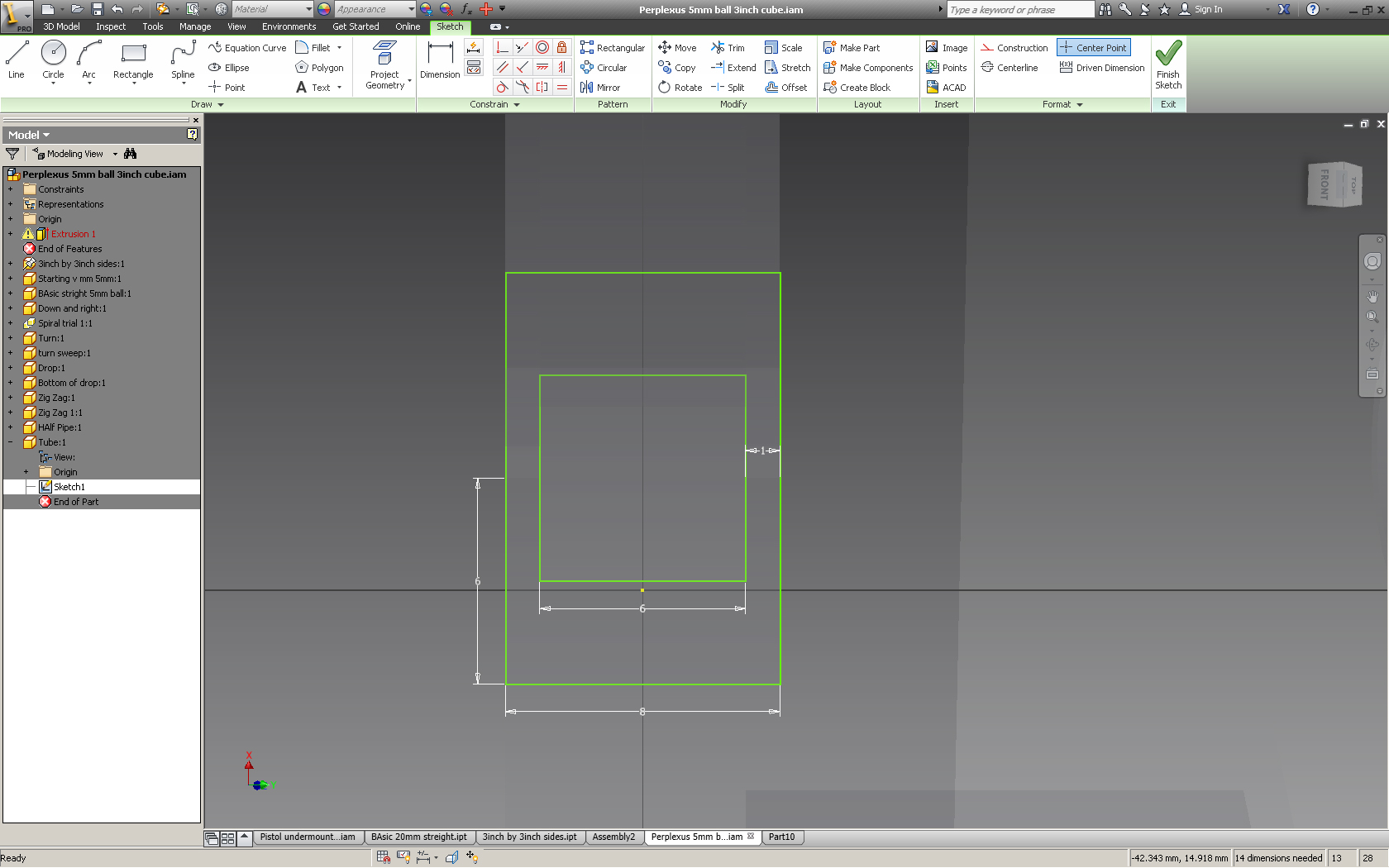
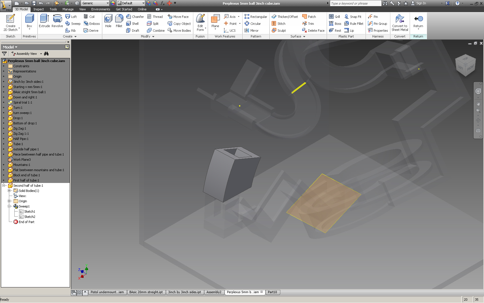
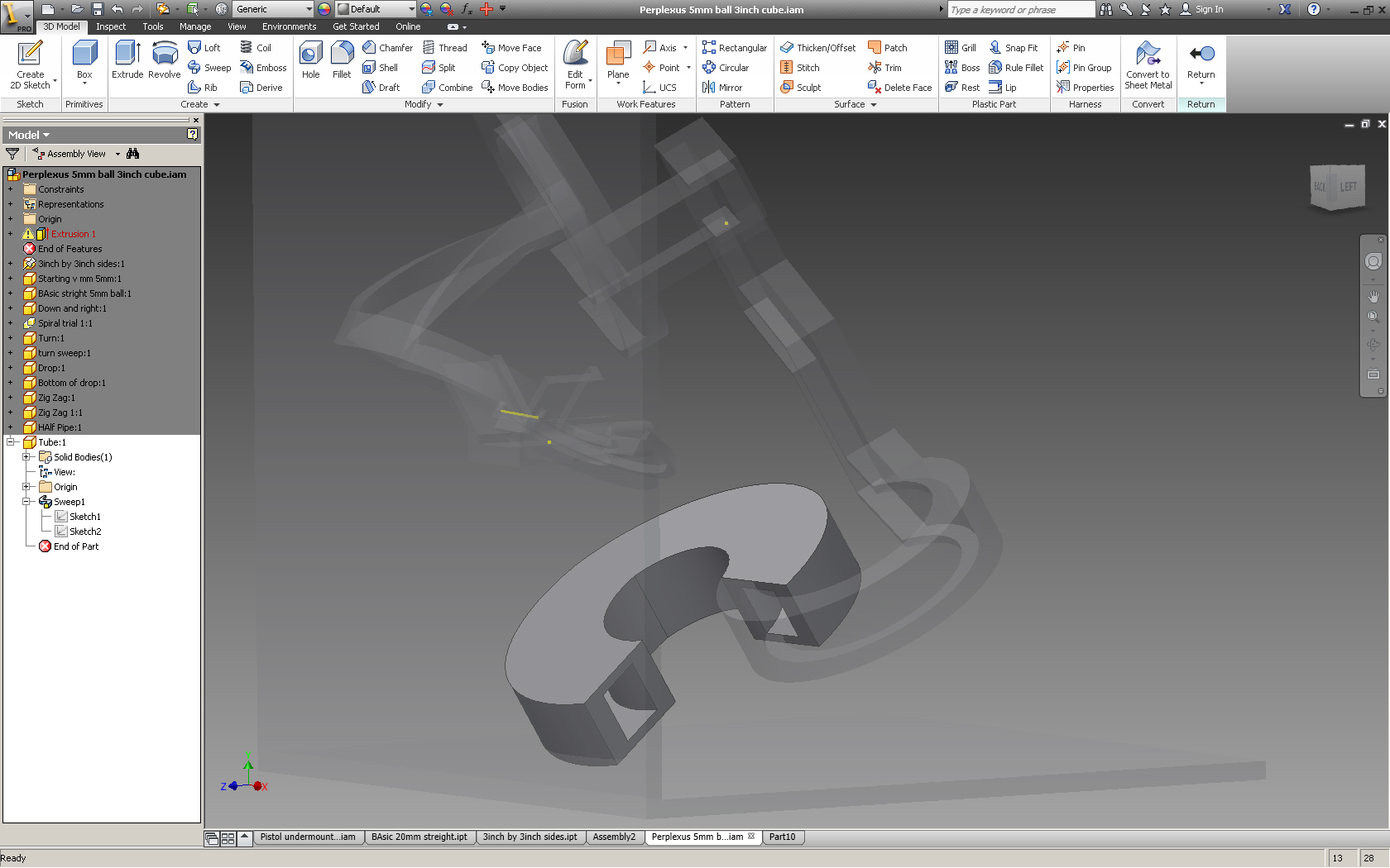
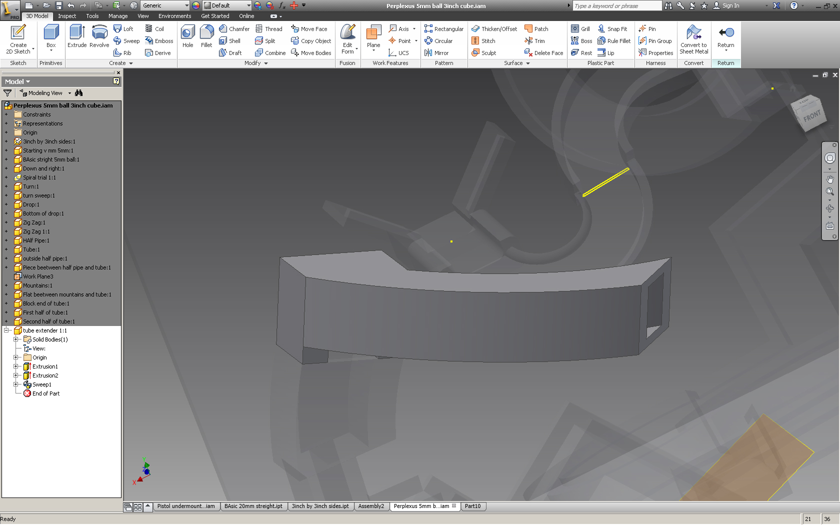
The tunnels or tubes are the same as the basic part except doubled so that the ball is enclosed on all sides. It is then swept just like any other part to make a tube that the ball can roll down.
Connecting Multiple Parts/ New Work Planes
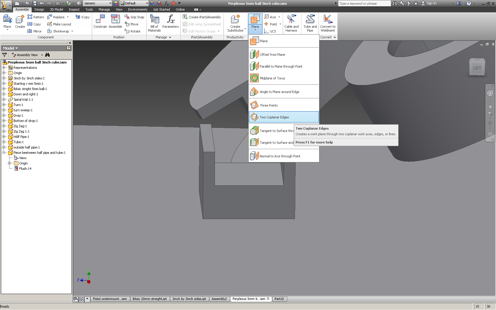
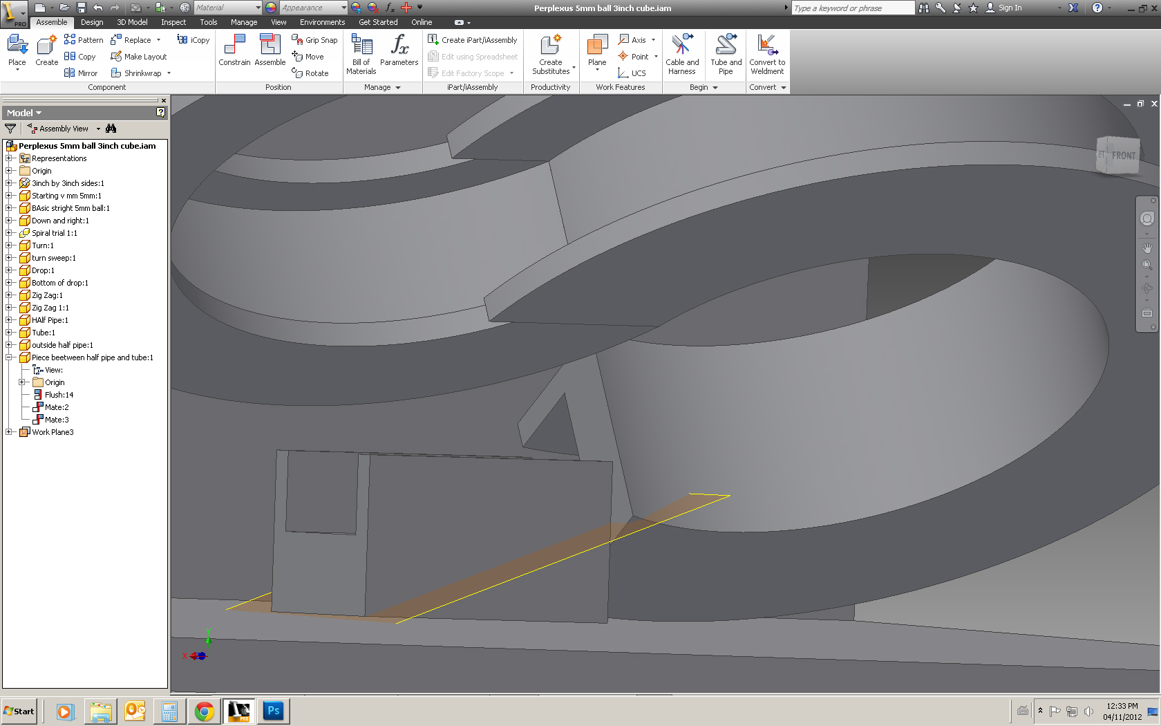
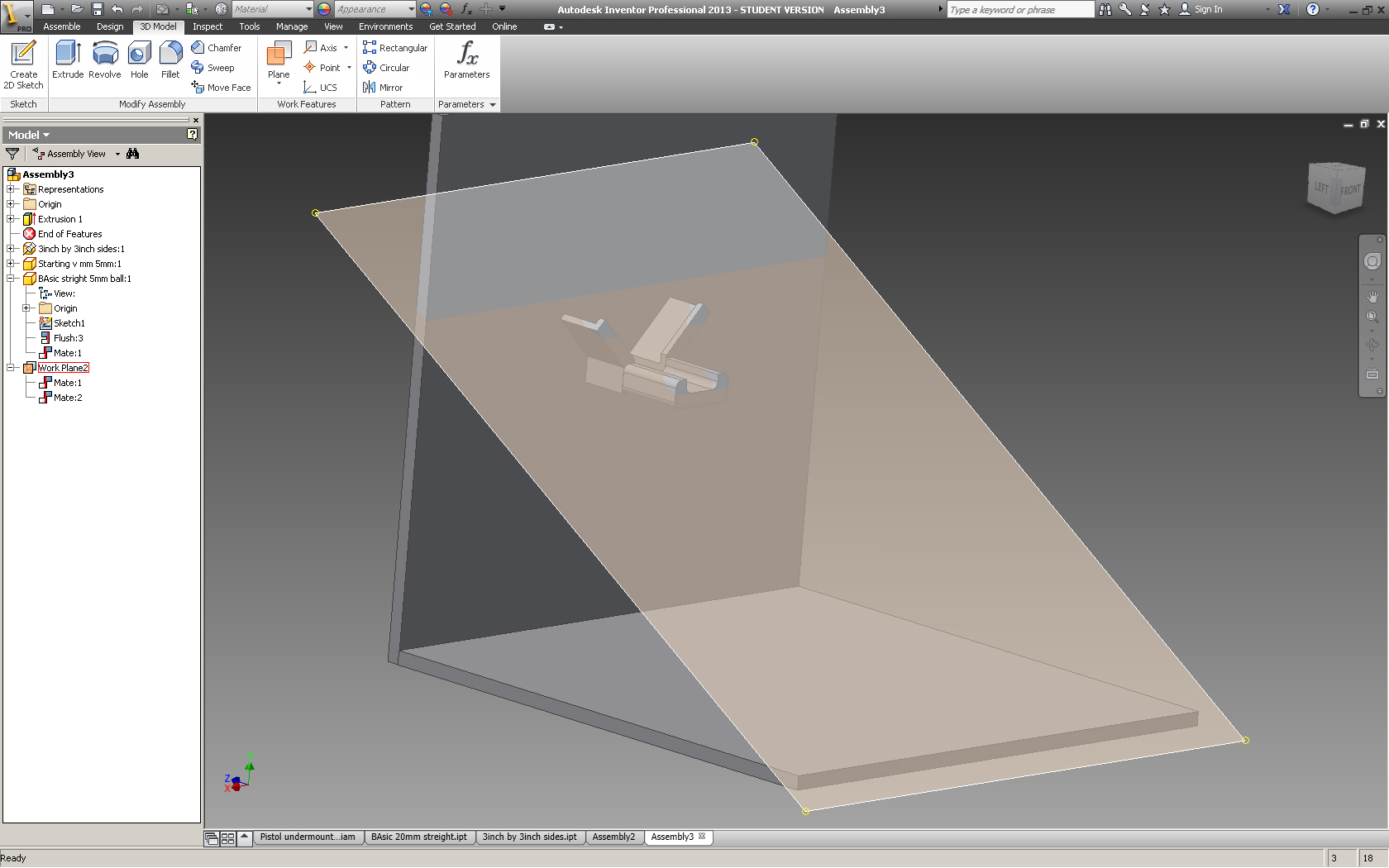
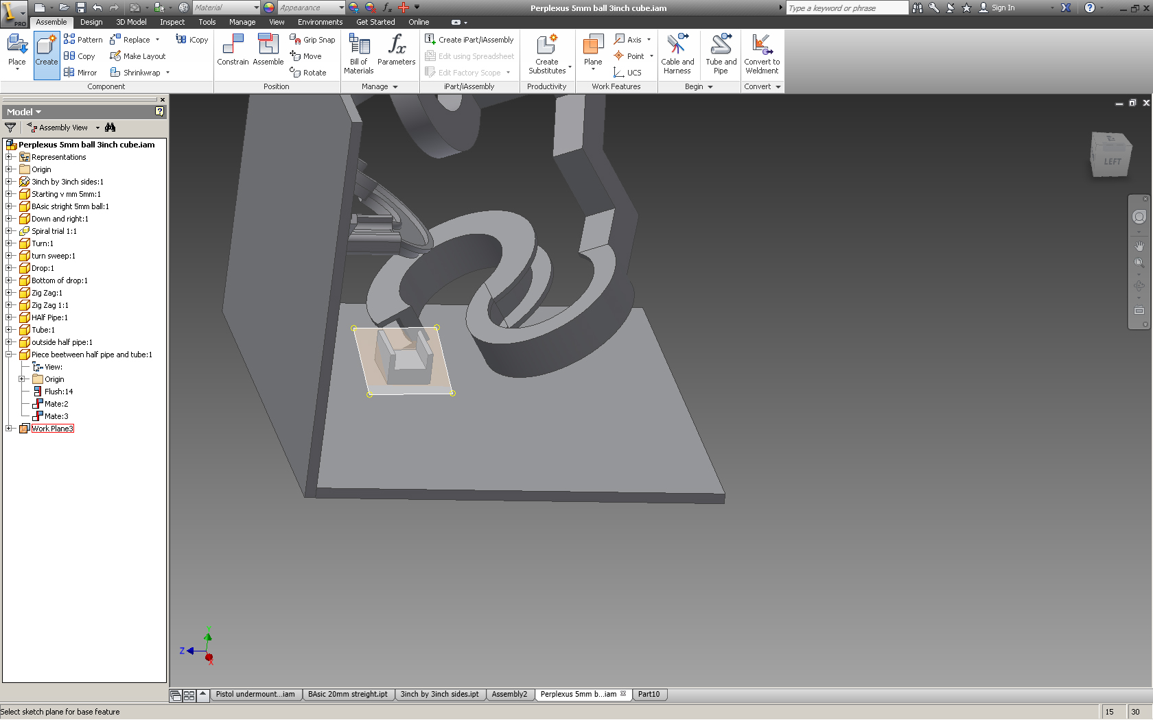
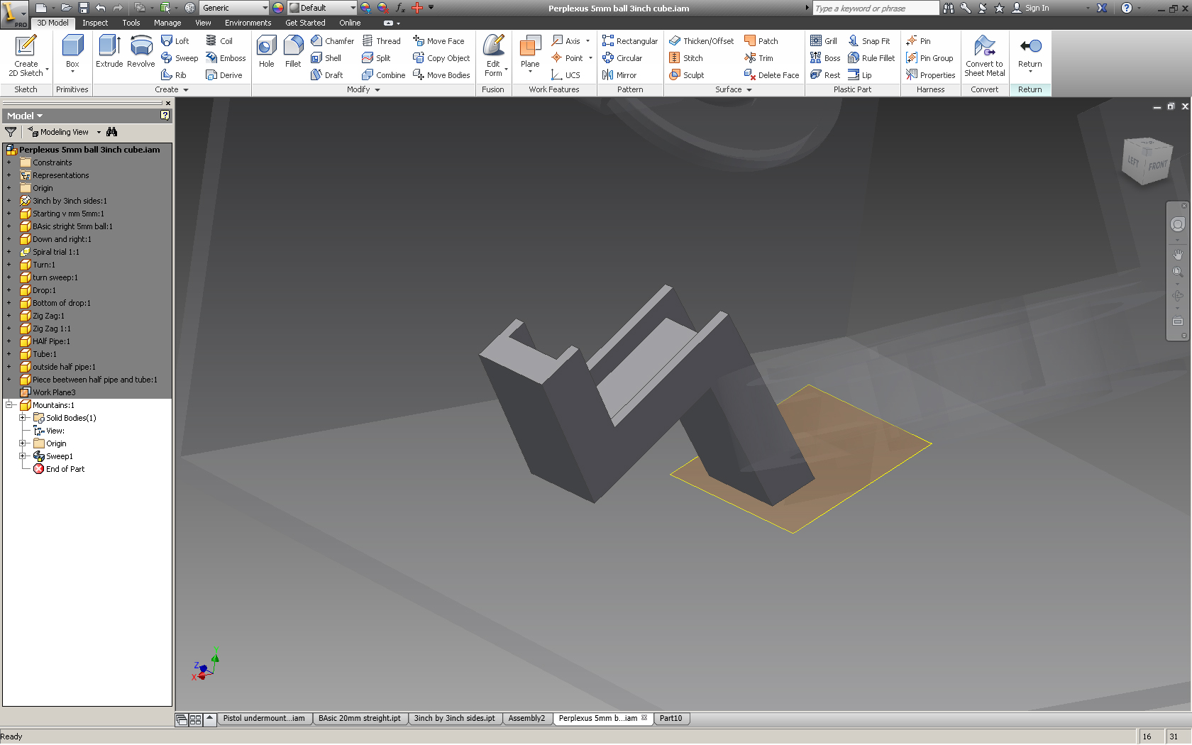
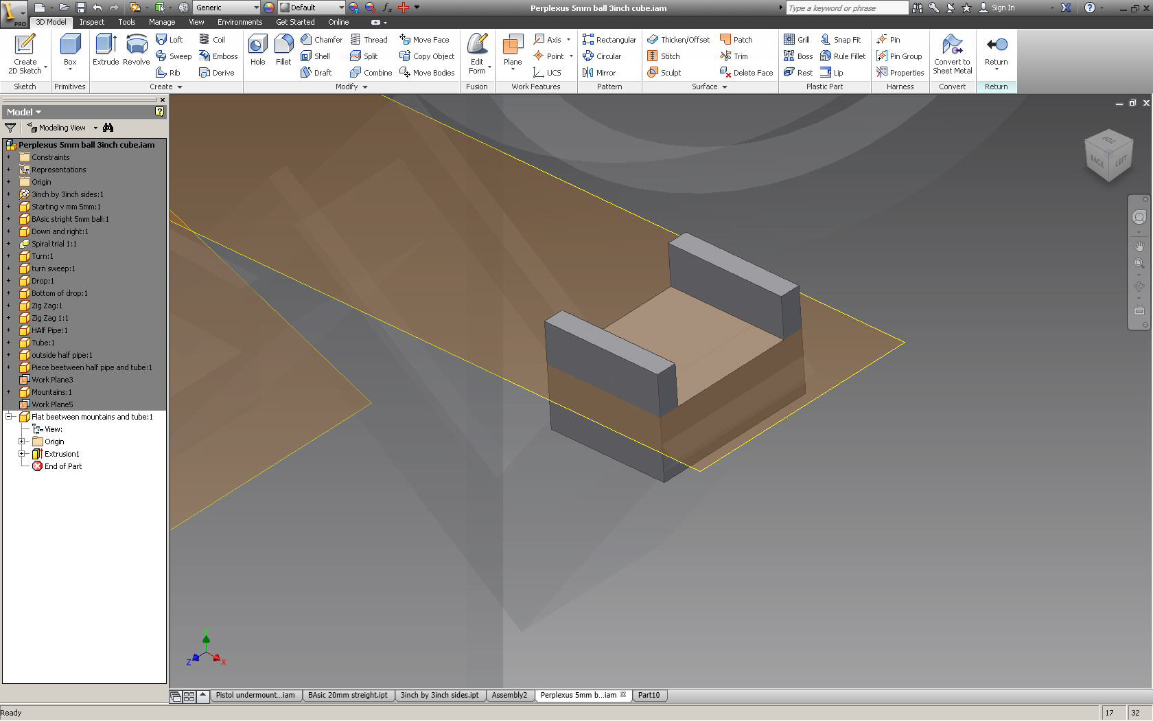
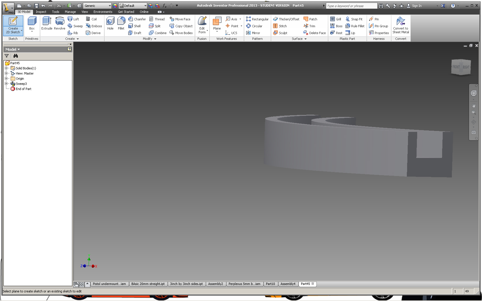
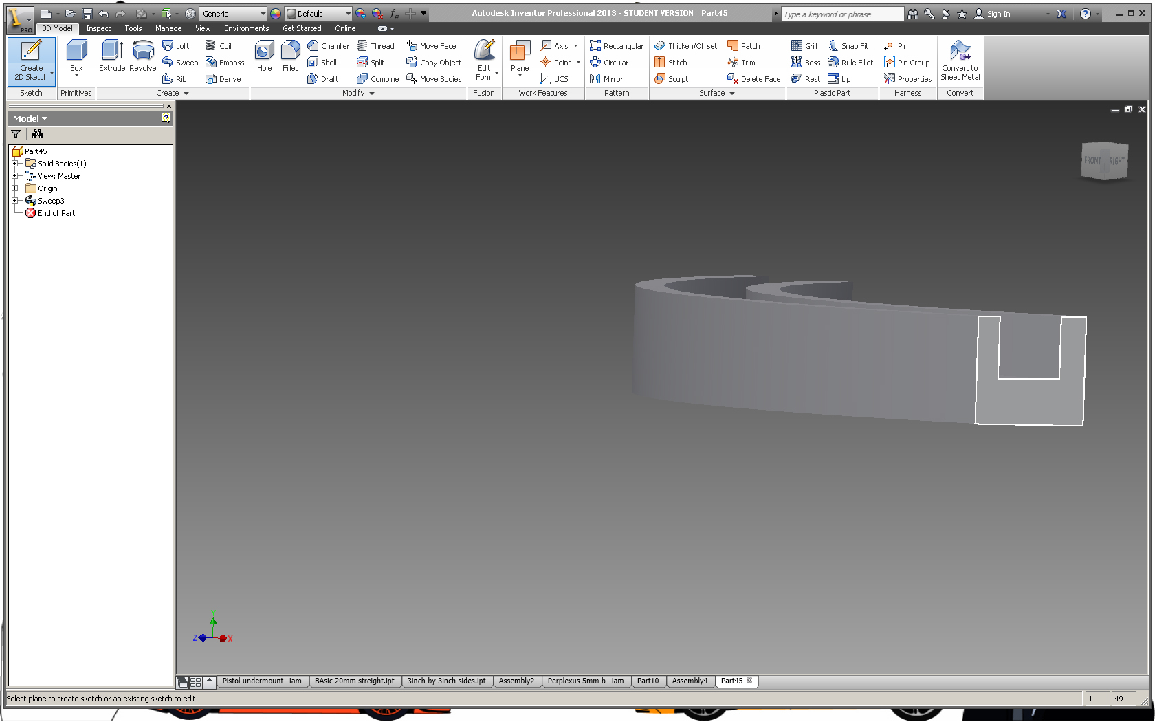
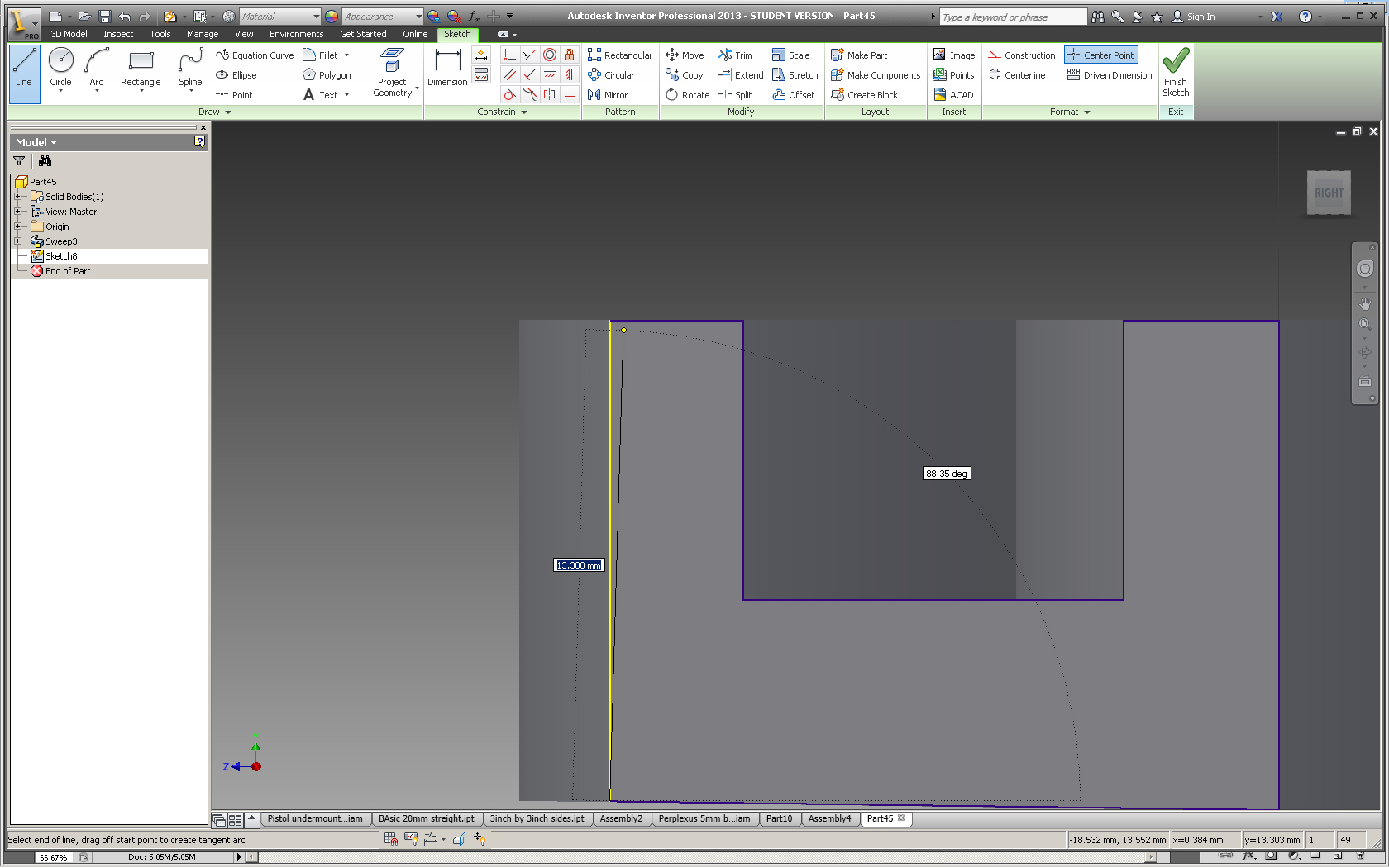
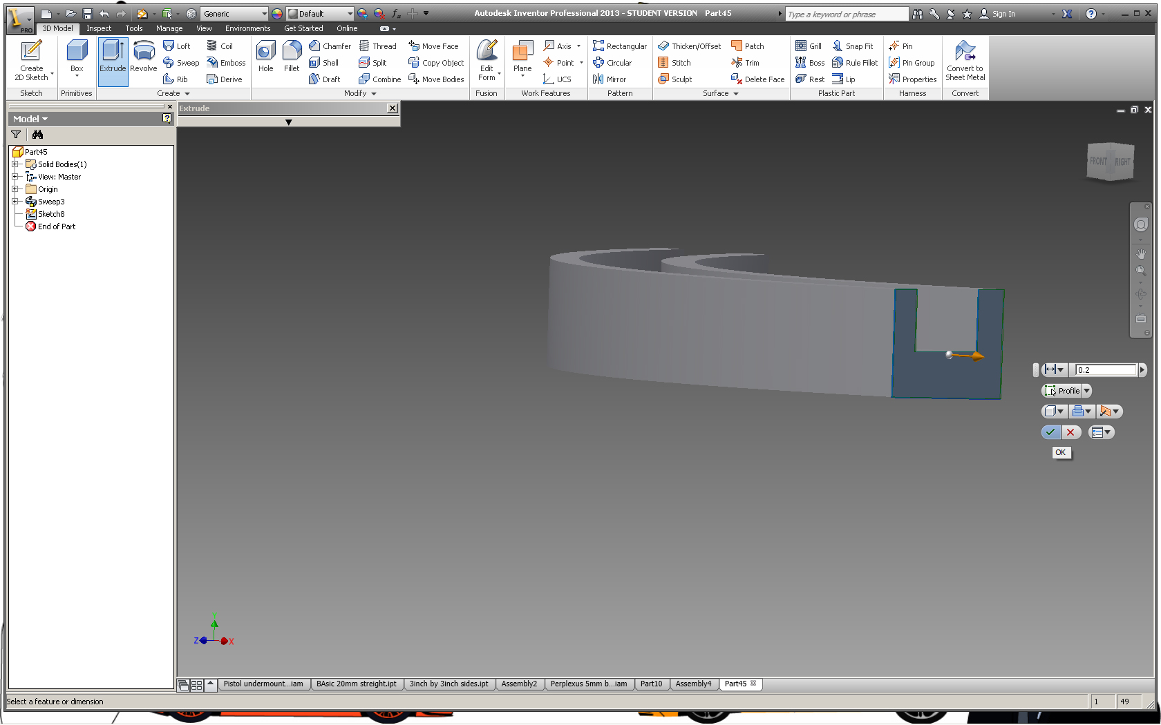
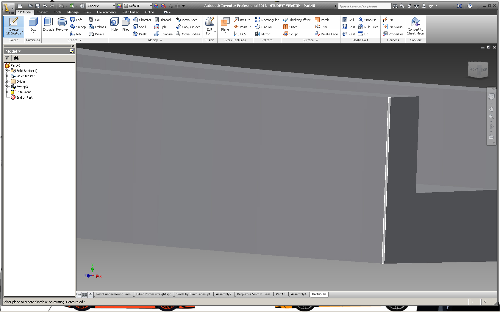
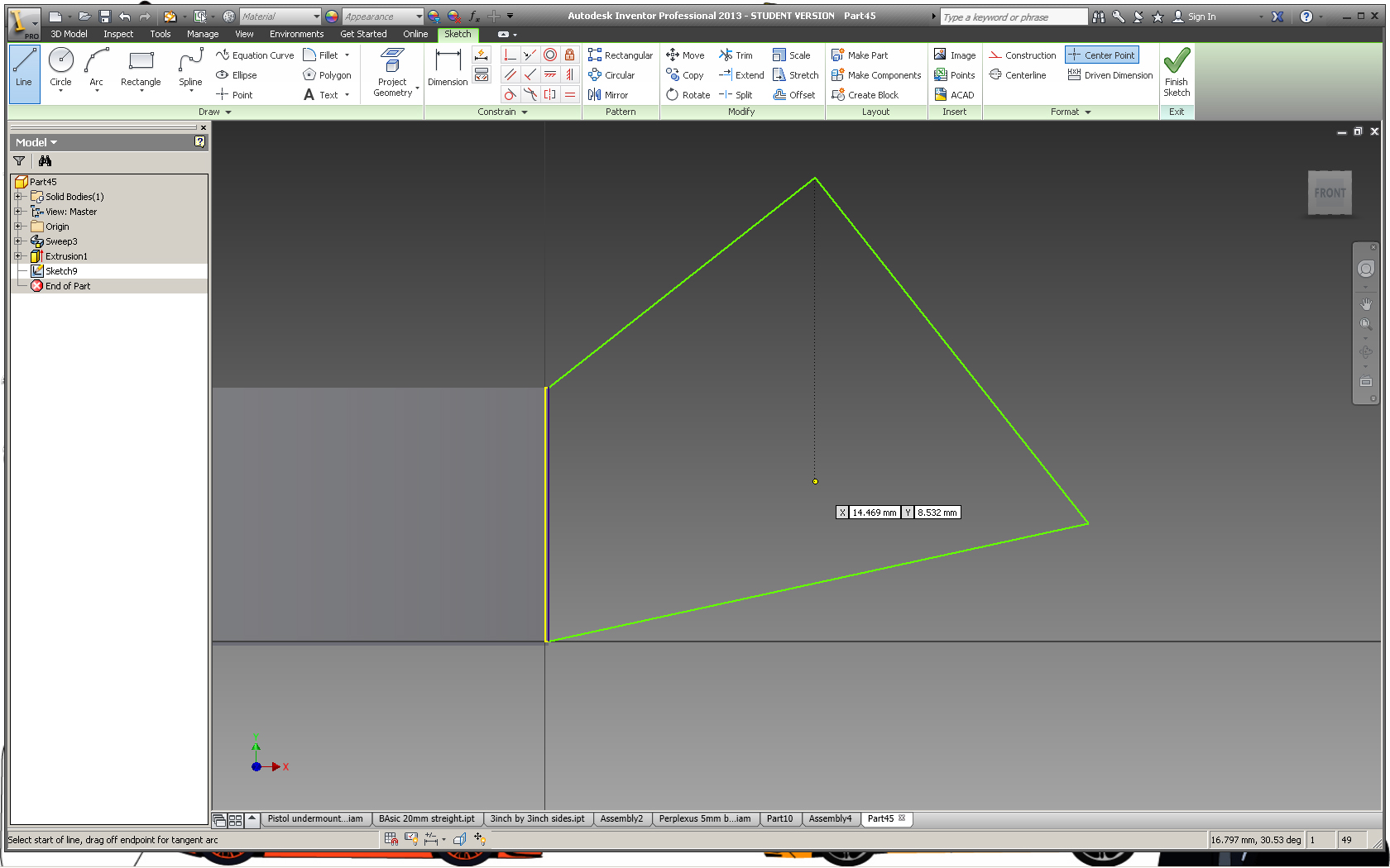
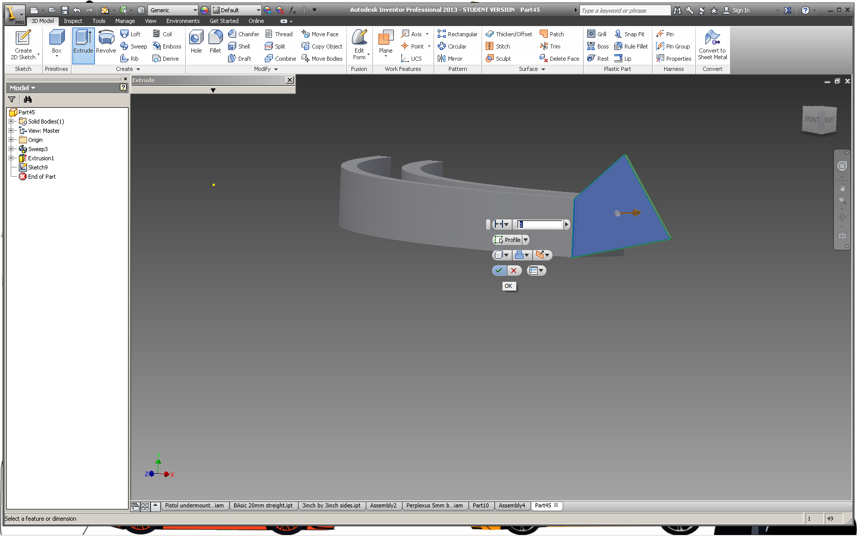
Now you may find that after making a bunch of sweeping and spiraling parts, you run out of flat faces that you can create a 2D sketch on. If this happens one way to fix it is to make a new work plane:
select the plane command in the assemble ribbon
Click the little arrow beside it and choose the two co-planer edges plane (or whatever kind you need to straighten it out again)
Next select 2 edges to make a plane on (it should appear in orange)
Create a new 2D sketch and select that as your work plane.
Method 2
Another good way is to create a new 2D sketch on the existing flat surface and then extrude it a little bit and then select any of the new flat areas to sketch off.
Finishing Touches Embossing
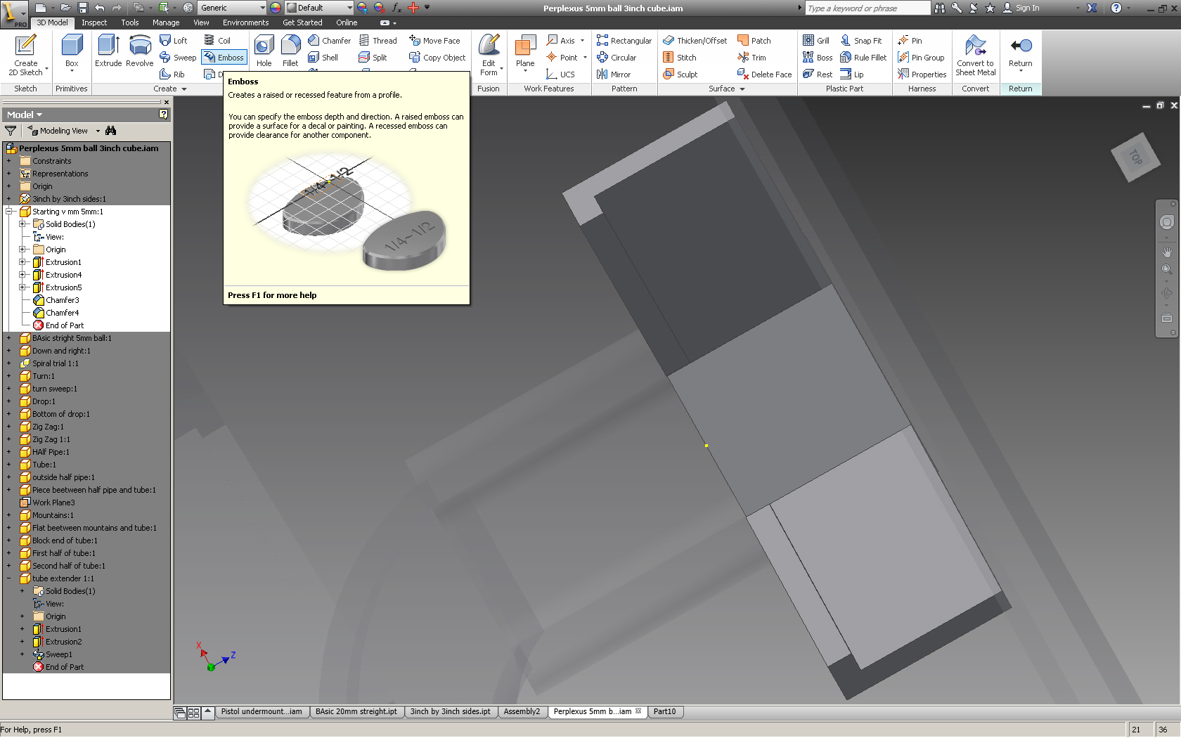
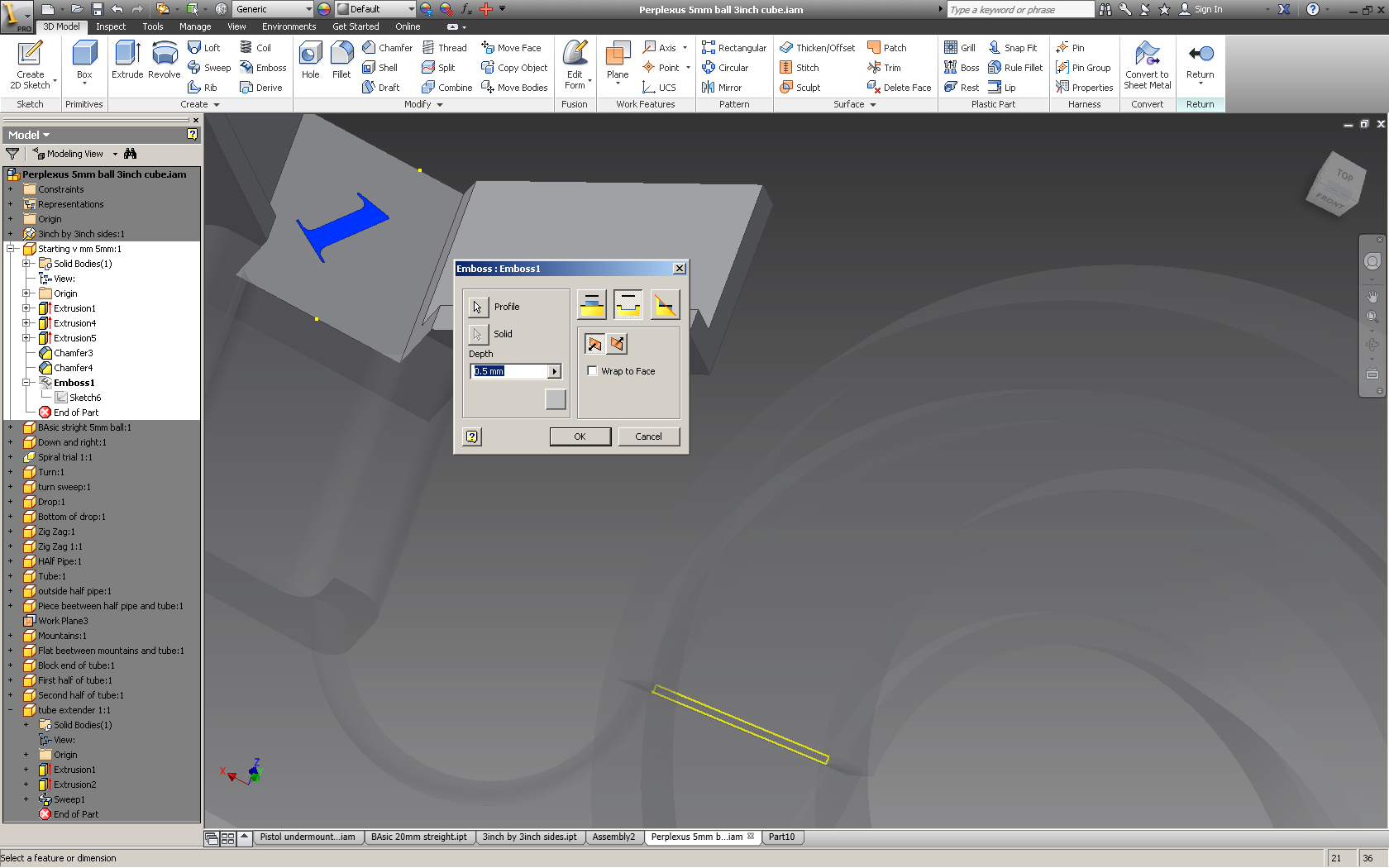
The real perplexus has numbers engraved into the plastic to show you which way to g and to tell you how far you have gotten. I wanted my version to have the same thing.
To emboss a number into a part:
create a new 2D sketch on the surface that you want to be engraved.
Finish the sketch.
Select the emboss command
select the number as the profile
select the appropriate depth 0.5 mm
select the second option in the box so the arrow turns red and faces towards the piece.
select ok.
repeat on all pieces.
If you wanted a smooth maze rather than the chunky looking assembly that I have made apply a fillet to as many edges as you like.
Save As .stl
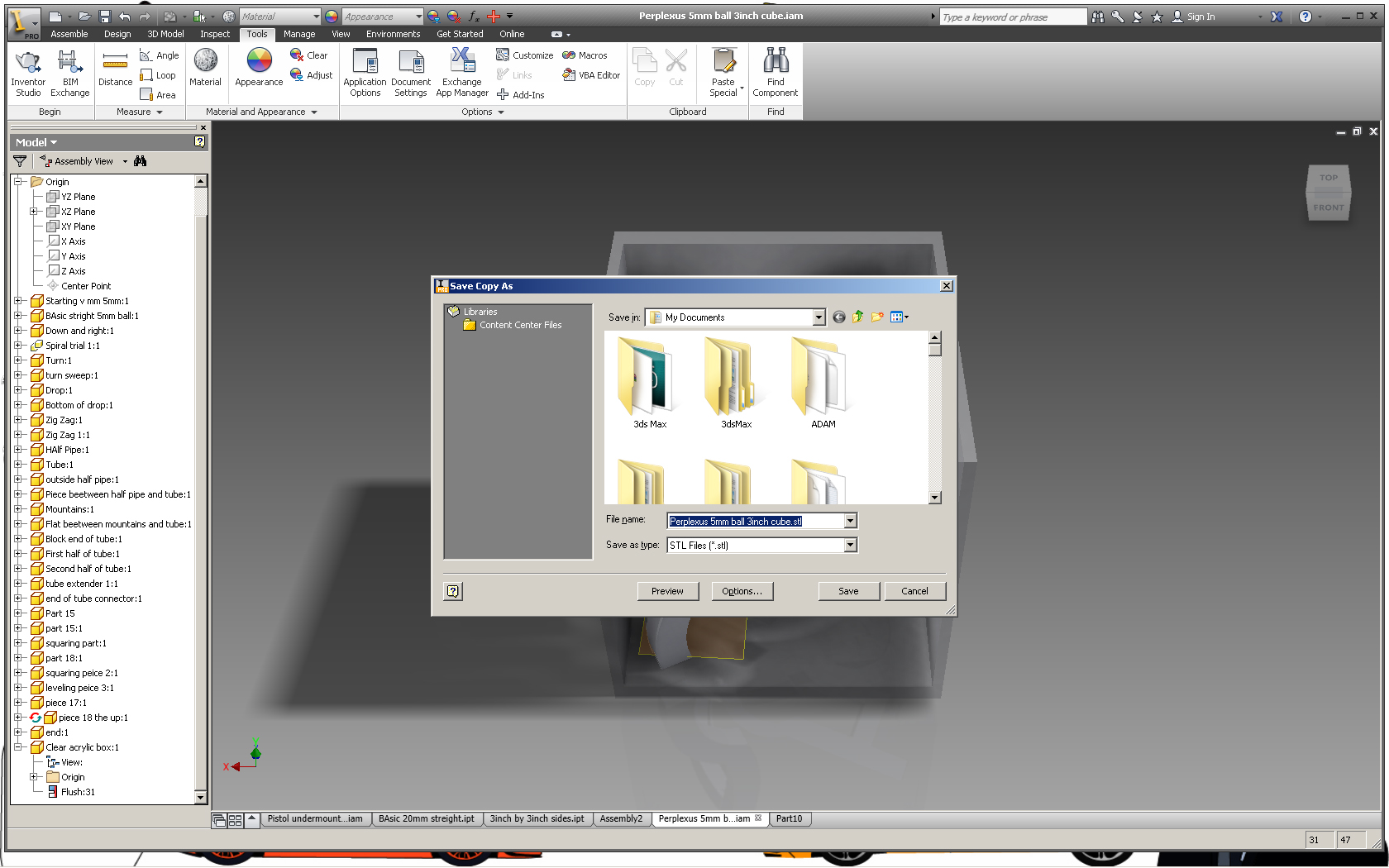

Now that you have the ability to create the parts, all that's needed is some creativity and patience and eventually you will end up with a cool little puzzle. Only problem is that it's digital, to create it in real life you will need to 3D print it. Instructables ans shapeways need you to email/upload a stereo litho file type. To make one of these from Inventor go to save as -- Save Copy As --> select .stl from the drop down menu. Go into the properties and make sure that the units are the same as the ones you are working with and that the detail is high.
Next if you are you are going to claim an Instructables print you need to email the .stl to free3dprints@instructables.com , in the email you need your instructables name, the Instructable that you won the 3D print from and the subject line needs to be Free 3D Print.
Next if you are you are going to claim an Instructables print you need to email the .stl to free3dprints@instructables.com , in the email you need your instructables name, the Instructable that you won the 3D print from and the subject line needs to be Free 3D Print.
Making the Cube
Once I have the part I will post pictures of it. I plan to color it with sharpies or paint.