Design Self-made CNC in Fusion 360
5302 Views, 26 Favorites, 0 Comments
Design Self-made CNC in Fusion 360
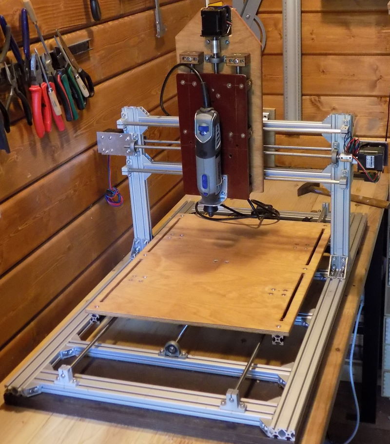
In this guidance we will run through the basics of the hand-made CNC machine design - we will cover basic topics of the Fusion 360 CAD software.
Fusion360 defines your creativity in a way that you can create your own CNC design, change its parts or size anytime and experiment with different parameters like profiles or sliders sizes etc. When you are eventually satisfied with your creation – then print BOM from Fusion360, order components and have fun with making your own CNC.
Our primary target is a low-cost customizable CNC for all makers and developers.
The possibilities are unlimited with the help of the CAD software
Fusion 360 Interface
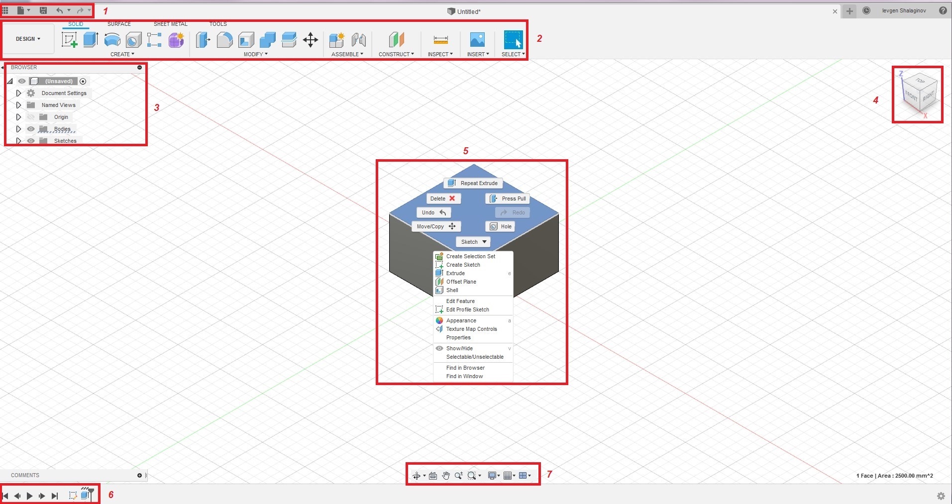
Fusion 360 interface
1. Quick access toolbar
2. Design toolbar with active modeling mode
3. Browser panel
4. ViewCube
5. Drawing canvas and a context menu (when you right-click the sketch). Use left click (LC) to select objects in the canvas and right-click (RC) to access the context menu with frequently used functions.
6. Timeline – displays all operations performed in the design. You can make changes by RC on the operations icon in the timeline, and you can change operation orders by dragging inside the timeline.
7. Navigation tools and display settings to perform zoom, pan and orbit functions. Additionally you can change the interface appearance like display settings and grid snap.
TIP: A different context menu appears when you right-click the grid, a sketch, or a selected sketch or body.
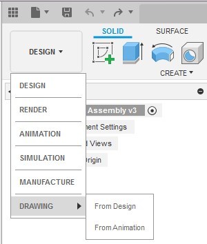
Available design workspaces
- Model: Create and edit solid models.
- Sculpt: Construct and edit T-spline models (organic forms).
- Patch: Create and edit surface models.
- Sheet Metal: Make and edit designs made of thin sheets.
- Render: Apply realistic colors and textures to the model
- Animation: Create visualization of how the design should work
- Simulation: Run tests to see how the model will perform under loads and stress
- CAM: Generate machine toolpaths to cut the model out on flat pieces of material.
- Drawing: Generate a multiview layout of the model. Modify and repair STL files (This workspace appears when an STL file is inserted).
Use the Mouse
1. Roll the wheel forward and backward to zoom in and zoom out.
2. Click LB and hold and then drag to pan.
3. Hold the Shift key and then drag with the middle mouse button to orbit the design.
4. Double-click the middle mouse button to zoom extents.
Use the mouse shortcuts to zoom in/out, pan and orbit the view. You can adjust default mouse controls in Preferences.
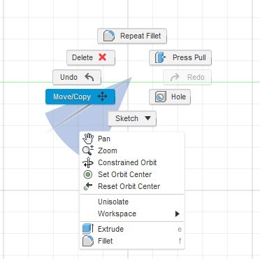
About the Marking Menu
You can access the marking menu by right-clicking anywhere within the drawing canvas. The marking menu is a radial display of the most frequently used commands. It also includes a quick access to all commands from the toolbar. Using the marking menu can be the fastest way to input a command in any workspace.
First Steps With Fusion 360
Import and open a file
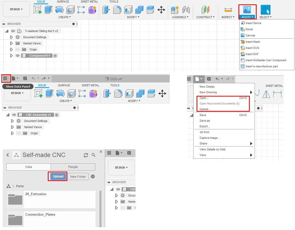
Click on the Show Data Panel button to import a file into active project by clicking button. Once it’s imported, the file.
Import files using Cloud Translators - Use the Upload command (you have to be inside of a project) to import a file into Fusion 360. Several file types can be imported into Fusion 360, including IGES, OBJ, STEP, STL.
Insert files and components - Use Insert button from Design toolbar with various Insert options to import components and files (OBJ, STL, DXF and SVG).
After Inserting or creating new design the Browser panel will appear.
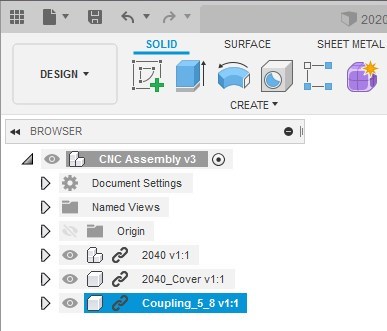
The Browser panel lists document settings, views, and the origin axes and planes. Click Document Settings to access units; you can change them here. Click Named Views to see the model in a top, front, or side position. Click the origin to see the different planes, this is useful for choosing a sketch orientation.
Every Fusion document has a single, default component called the root component. The browser’s top field shows its name, which is Unsaved until you save it. Right-click it to access functions. As the model evolves everything— sketches, bodies, components and assemblies— it is listed in the Browser panel. You can edit these items through the browser and control their visibility. Items appear with default names like Component 1:1, Component 1:2, or Body. The first number is the version number, and the number after the colon is the copy number. You can rename all browser entries to do so click the text field to activate it, type a new name, and then press Enter.
Each browser entry has a light bulb in front of it. When the bulb is yellow the item is visible; when the bulb is gray the item is hidden.
Navigation in Fusion 360
Use the ViewCube to rotate the camera; by dragging the ViewCube you will perform a free orbit, and through clicking faces and corners of the cube you can gain access to different views.
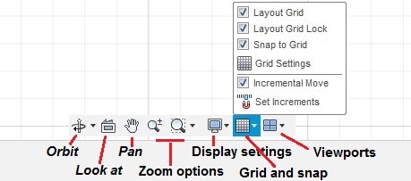
The Navigation panel contains tools that let you zoom, pan, and orbit. It also has display settings that affect the workspace and how the model appears. You can change the grid size, change how the mouse snaps to the grid, see the model as wireframe, and see multiple views of it on one screen.
Quick Object Creation in Design Workspace

Creating simple T-fastener Sliding Nut 5
Before we are going to the complex shape design I will show you how to create a simple object with the help of the CREATE tool palate.
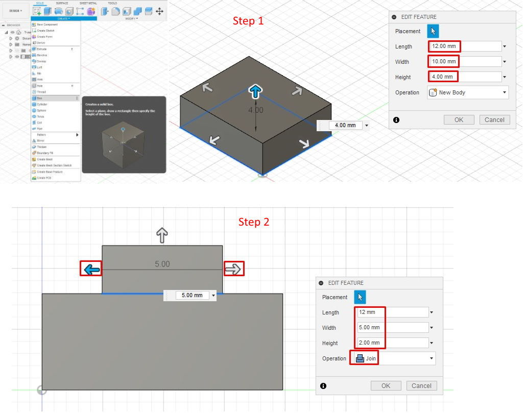
Step 1: Create a Box
1. Click the File menu. Select New Design.
2. RK in the Browser panel and select New Component
3. Click Create > Box.
4. Select the XZ Plane along the bottom of the canvas.
5. Pick two points to define the length and width of the box. You can easily change the box dimensions at any time with the mouse by pulling the handles or in the object properties window.
6. In the Box dialog, enter:
- Length: 12 mm.
- Width: 10 mm.
- Height: 4 mm
7. Click OK
Step 2: Creating second Box
1. Click Create > Box.
2. Select the top Plane of the first box.
3. Choose two points to define the length and width of the box.
4. In the Box dialog, enter:
- Length: 12 mm.
- Width: 5 mm.
- Height: 2 mm
- With the help of the left and the right handle you can position the box in in the middle of the first box.
- Operation – Join
5. Click OK
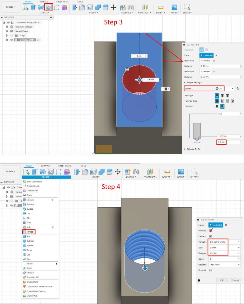
Step 3: Place hole in the middle
1. Select Hole tool
2. Select the top face of the second box , as reference select the top edge and type 6 mm in the dimension field and then right edge and type 2.5 mm to position our hole at the center. Additionally in the dialog box type the hole dimension 3.8 mm and select Extents > All
3. Click OK
Step 4: Creating a thread
1. Select CREATE >Thread
2. In the dialog window select::
- Face of the hole
- Thread Type – ISO Metric profile
- Size – 5 mm
- Designation - M5x0.8
- Don’t forget to check Modeled
3. Click OK
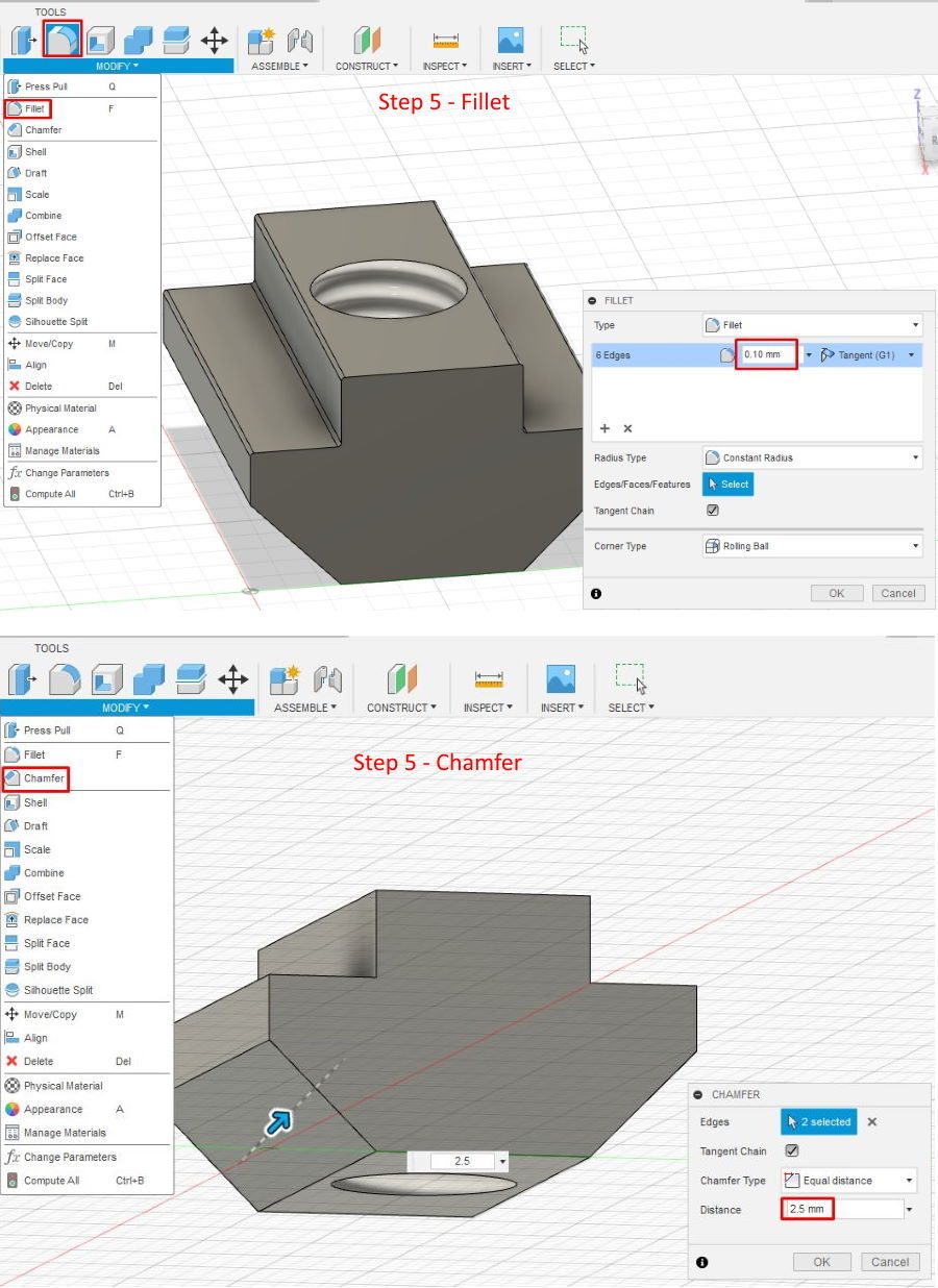
Step 5: Round the Edges by using Chamfer and Fillet commands
- Select the top edges
- Press the Filet button
- For Radius, enter 0.1 mm.
- Click OK
- Select the bottom edges
- Press the Chamfer button
- For Radius, enter 2.5 mm.
- Click OK
Step 6: Save Your Design
- Click Save.
- In the Name field, enter T-fastener Sliding Nut 5. Click Save. The design is saved to the current project in the cloud.
Amazing part of the Fusion 360 is a Design History Timeline.
You can select any design step and change it, like for example you can select add a hole step and then change hole diameter to 45 mm – depending on the spindle diameter. Right-click the third item in the Timeline—the first should be a sketch, second initial extrusion and the third is hole operation. Next, click Edit Feature, and the original hole dialog box should appear. Now change the diameter from 3.8 mm to 2.5 mm and then click OK.
Also you can use the Back and Forward buttons to skip back and forth through all of the features to see each step. When you use the timeline to make changes to an earlier step, changes will be applied to all operations – in this way you can any time adjust your design.
Downloads
Create 2020 Extrusion - Part 1
Insert sketch into fusion
You can create your sketch from scratch or you can insert it from the file (DWG, DFX, SVG, JPEG etc.).
There are three ways to do this: inserting into the workspace, uploading to the Data panel, or uploading via the New Design from the file.
Inserting into the Workspace
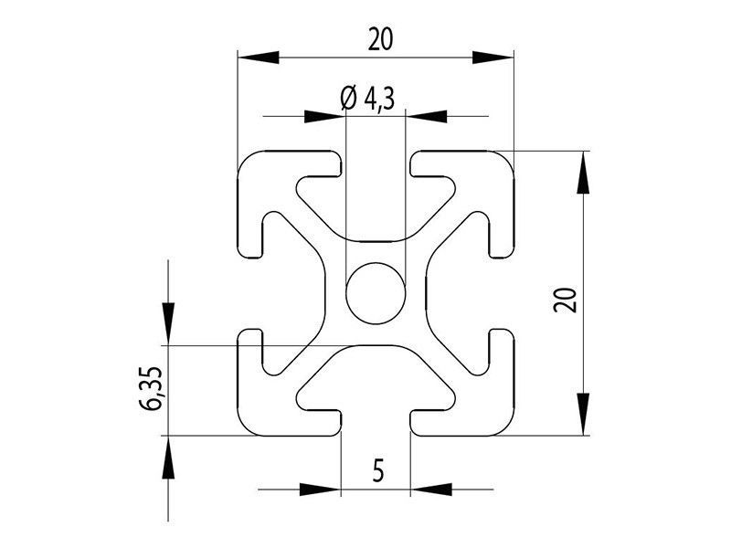
To learn some basic design functions we will insert a JPEG image of the 2020 extrusion as reference and then draw a sketch accordingly.
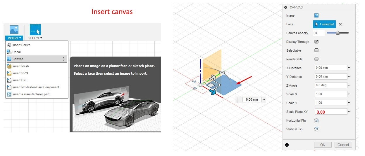
The DXF (Autodesk Drawing Interchange Format) and SVG (Scalable Vector Graphics) files can be inserted directly into the workspace. In the Insert menu we can find Insert SVG and Insert DXF, but for the JPEG file type we must create canvas. Select Insert -> Canvas the popup window for selection of origin planes and a file folder will appear. Select the JPEG file from your hard drive, then select the plane you want to draw on and press Enter.
The graphic will appear with a dialog box to move and scale and change image properties. We can center our image and change the opacity etc. We will now position our graphic in the middle and press OK.
TIP: To simplify the draft process you can scale the image, in our case Scale is 3.
Create Sketch
Then we will create a sketch by pressing the Create Sketch button in the Design toolbar. After activating a Sketch tool, you will make most sketches with three steps. The first selects the sketch plane, the second draws the sketch and third finishes the sketch by pressing Enter.
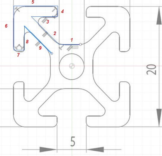
First we will draw a few lines on the graphic contour – select Line tool in the Design Toolbar and by clicking LB select the first point and afterwards drag the cursor to the next point to create the first line. The Line tool is still active so you can draw lines from 1 to 9 in the same way and then press Enter.
NOTE: You can draw shapes by dragging the cursor or type dimensions in the according boxes which will appear during the drawing presses
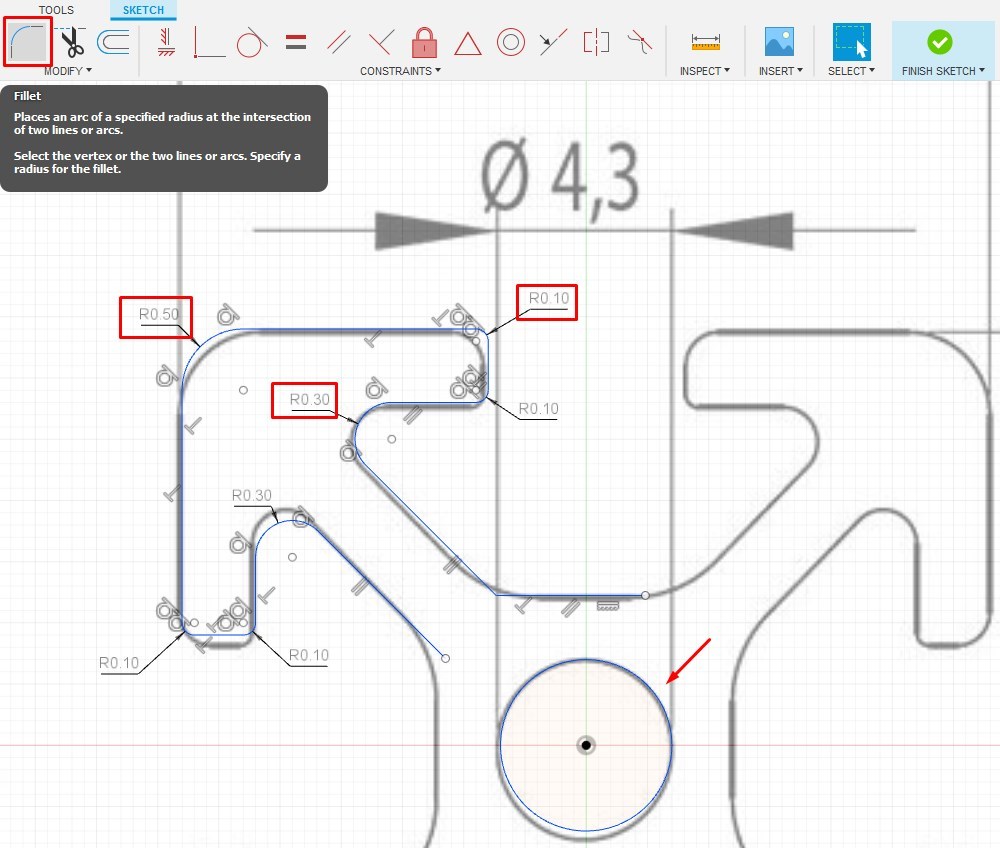
Now we will place the circle at the center point (XY axes intersection point) and then we will apply Fillet tool to our corner. You can use the same dimensions as I am 0.1 mm small fillets, 0.3 mm on the inside corners and 0.5 mm on the edge; or you can apply your own dimension because the sketch dimensions can be changed at any time.
INFERENCES AND CONSTRAINTS
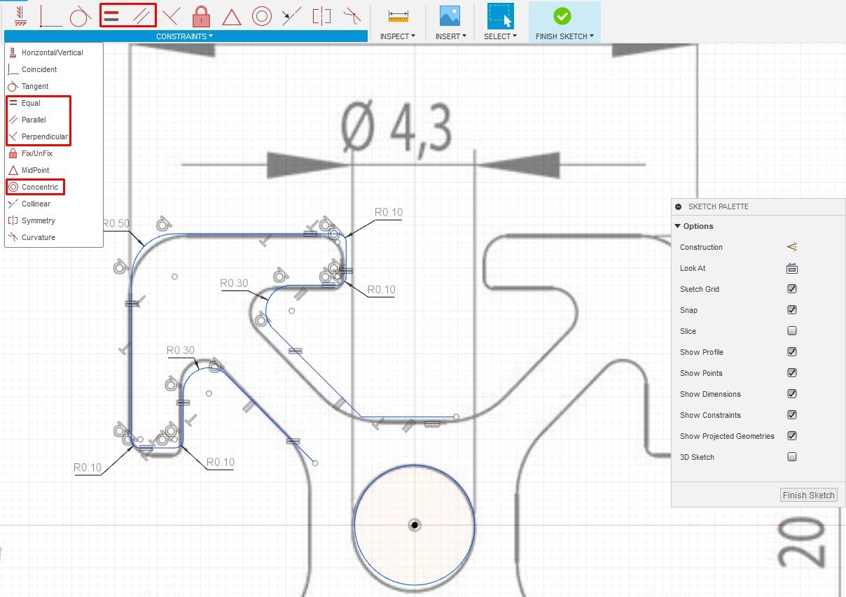
We can already see some constrains placed by Fusion360.The sketch also has symbols in the near of the drawed lines, the so called geometric constraints. These are limitations you apply to the sketches. Geometric constraints enforce relationships between parts of the shape; you can constrain a drawing so that two lines are always parallel or perpendicular to each other. Click a constraints icon in the tool bar and then click two sketch items to apply it. The lines will adjust accordingly. To exit from applying a constraint press the Escape key or right-click and choose Cancel.
A fully constrained sketch means you can click any point on it to move it and it will move as a whole without changing its shape. None of its lines can move independently. When a sketch isn’t fully constrained, a part of the sketch will move and change. The advantage of a fully constrained sketch is that it will always maintain its shape.
Press Escape or Enter or right-click the shape and choose Cancel to cancel the tool without exiting the sketch.
We will apply Horizontal, Vertical and Perpendicular constrains to the straight lines by selecting the relevant constrains from the toolbar and clicking line with LB. Place Parallel constrains to the inclined lines.
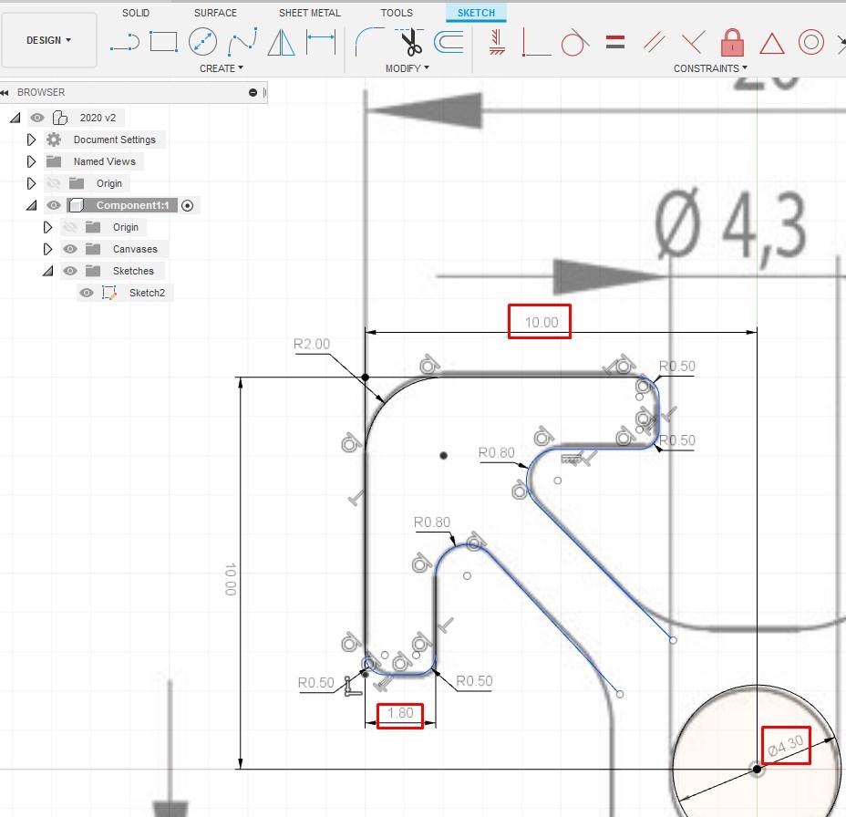
After that we will place dimensions:
- 10 mm for horizontal and vertical dimension from the center to the corner
- 4.3 mm circle diameter
- 1.8 mm wall thickness
- 6.35 mm from outside corner to the inside extrusion body
And an Equal constrain to the lines 5 and 6, then 4 and 7 and 3 and 8. If you make some fail placement, afterwards you can easy delete it – to do so select its image in the sketch and press Del.
NOTE: If Fusion already placed the same constrain which you are trying to apply then you will get some error message, which is not critical – in this way Fusion wants to tell you that the same constrain is already applied.
At the end our sketch should look similar like the picture, but even if your sketch is a deviate from my design it’s not a problem, because you can adjust and change your sketch at any moment. Additionally, I placed a circle in the middle with Concentric constrain.
Create 2020 Extrusion - Part 2
Now we will speed up our work by applying patterns.
Patterns
Patterns is very useful and a time saving tool for creating complex profiles and objects. In our case we can quickly create a sketch of our 2020 extrusion and then extend it to 2040 or 2080 etc.
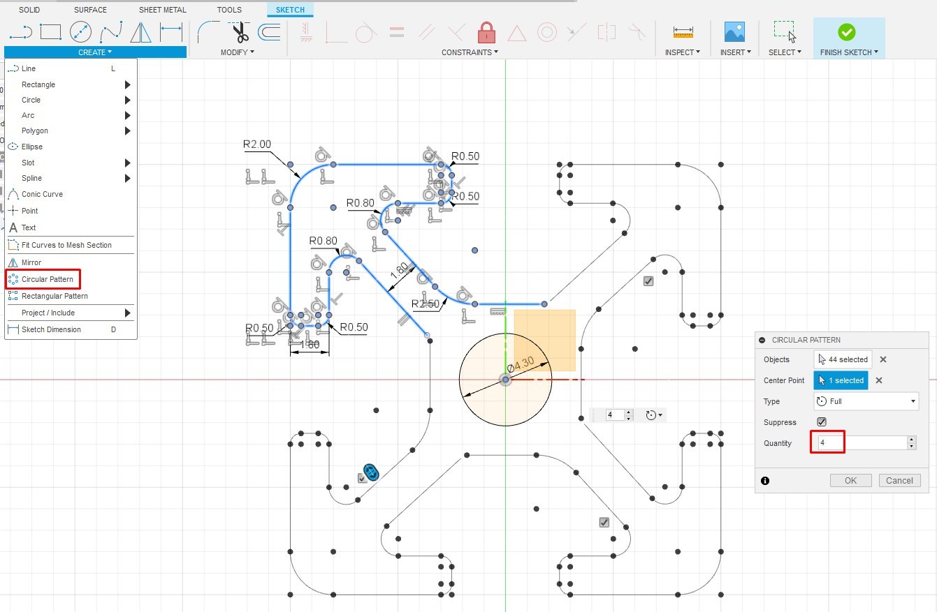
Circular Pattern: This tool copies and arranges a selected sketch part or whole sketch around a circle. It can array completely around the circle or just partially. The sketch must be in Edit mode.
Select the part of the sketch (in our case drawn lines), activate the Circular Pattern tool, click the Center Point button in the dialog box, and then click a center point (the point around which the sketch is arrayed). Handles and two copies will appear. Drag the handles forward to add copies; drag them backward to subtract copies. Or just type the number of copies wanted in the text field. Click OK to finish. If you change the dimension of one sketch later, all the arrayed copies will change, too. In the dialog box select Quantity 4 and click OK.
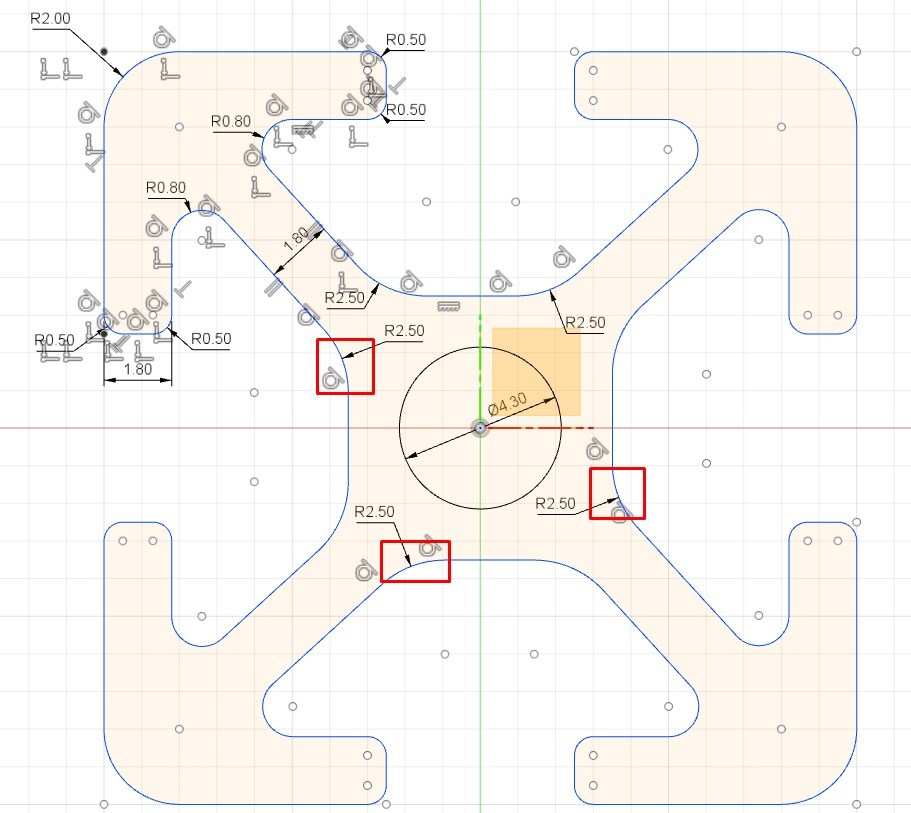
After the circular pattern is applied – define dimensions from the center to the edges and place the dimensions according to the reference graphic. Apply Collinear constrains if some lines are shifted.
INFO: If by placing some of the dimensions you will receive warning messages that the sketch is over – constrained, press OK and this dimension will appear reference.in the brace.
Apply fillets to the lines inside our 2020 extrusion to close the sketch.
When all the endpoints are connected it will form a face with another lines color. This is called a closed-loop, or closed sketch. An open sketch has nonconnecting endpoints and therefore, no face. Most operations must be performed on a closed sketch.
Then we will apply Horizontal, Vertical and Equal constrains to those lines.
NOTE: Sometimes some problems by sketch closing appears and to solve it you should remove some constrains.
When you’re finished with the sketch, click the Stop Sketch icon in the upper right screen, or right-click and choose OK.
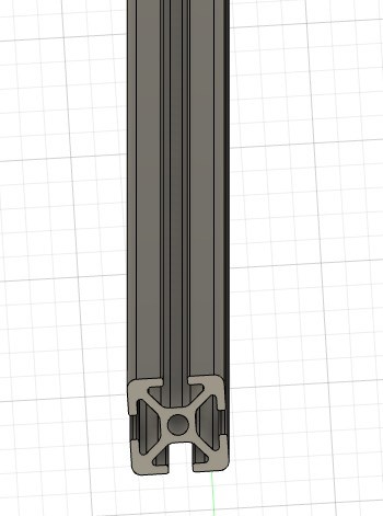
After that you can extrude a 2020 profile.
Downloads
Extend 2020 Extrusion to 2040
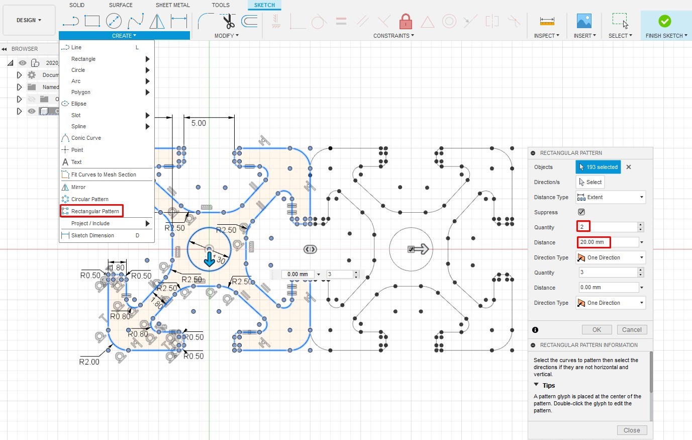
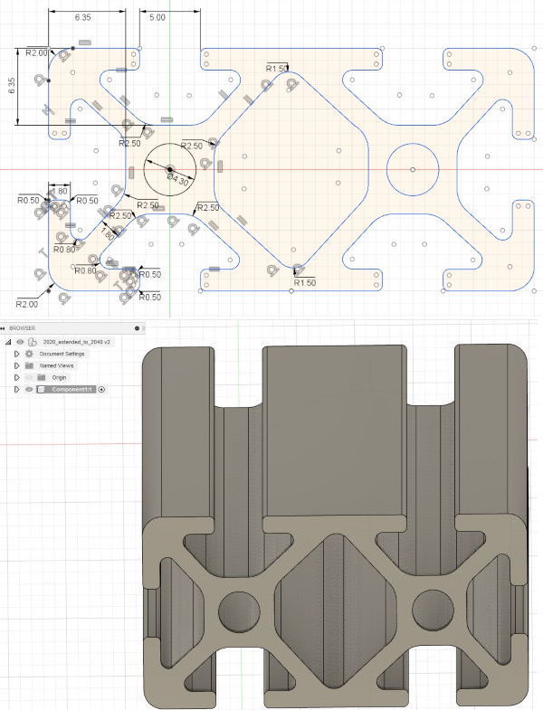
Rectangular patterns
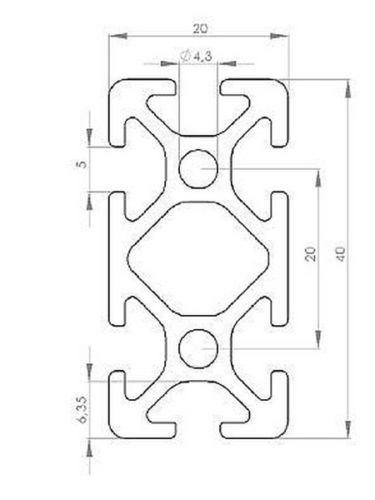
With the help of the rectangular patterns we can transform our 2020 into 2040 or 2080 profile etc.
With this tool you can make copies of the selected sketch in a row or column pattern. In the Edit Sketch mode select the profile sketch and then activate the Rectangular Pattern tool - then drag the arrows back and forth and up and down to create rows and columns, or type how many rows and columns you want.
In the dialog box you can specify the direction, the distance between copies, symmetry etc. Play with different options to be familiar with this useful tool.
Thanks to the patterns you can extend your design in an any possible way.
TIP: I prefer to save all my designed components in separate files – it will simplify the assembly process and some future design changes.
Downloads
Projection
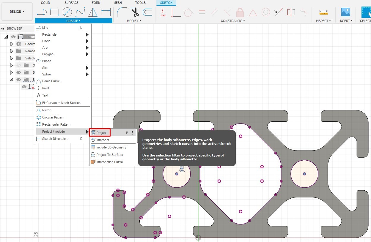
Project
We learned how to draw a sketch – but another even easier way is to use Projections.
1. Download the STP model of the desired part from the manufacture website
2. Insert it in the project File > Open…
3. Select the same plane as the profile bottom (usually XY)
4. Create new Sketch
5. CREATE > Project/Include > Project
5. Select all edges by Ctr + LC and press OK in the pop-up window.
Now you do have a sketch for your own part which you can adopt to your project.
Modeling a Trapezoidal Threaded Nut
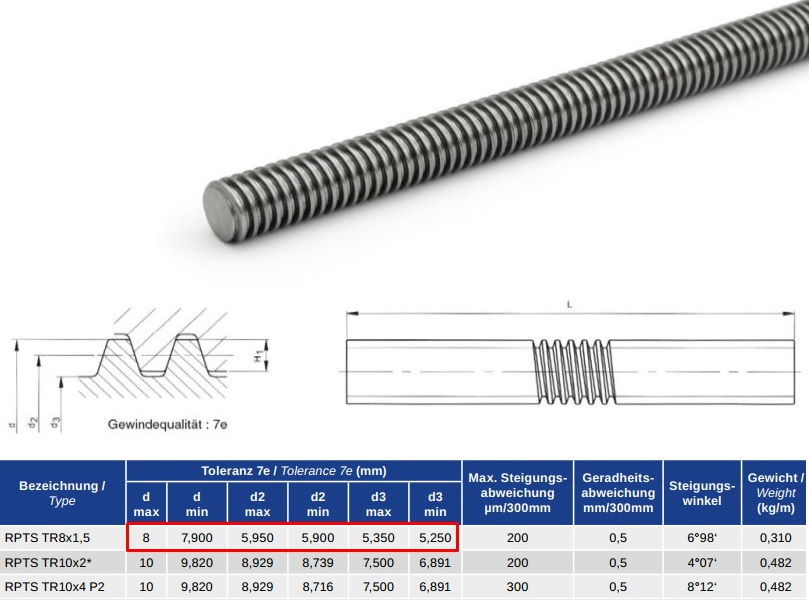
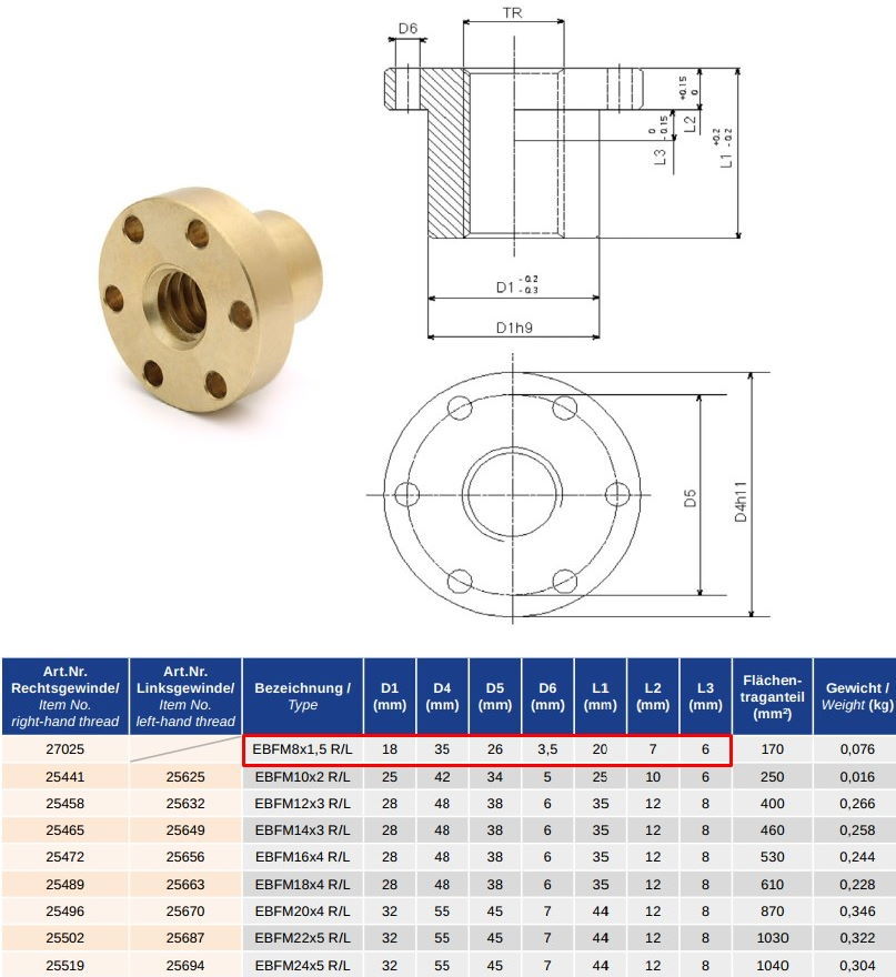
Creating a Trapezoidal threaded nut
- Create New Design and in the browser RK and select New Component
- Save your design
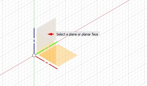
- Create a Sketch - for body of rotation we usually select YZ plane
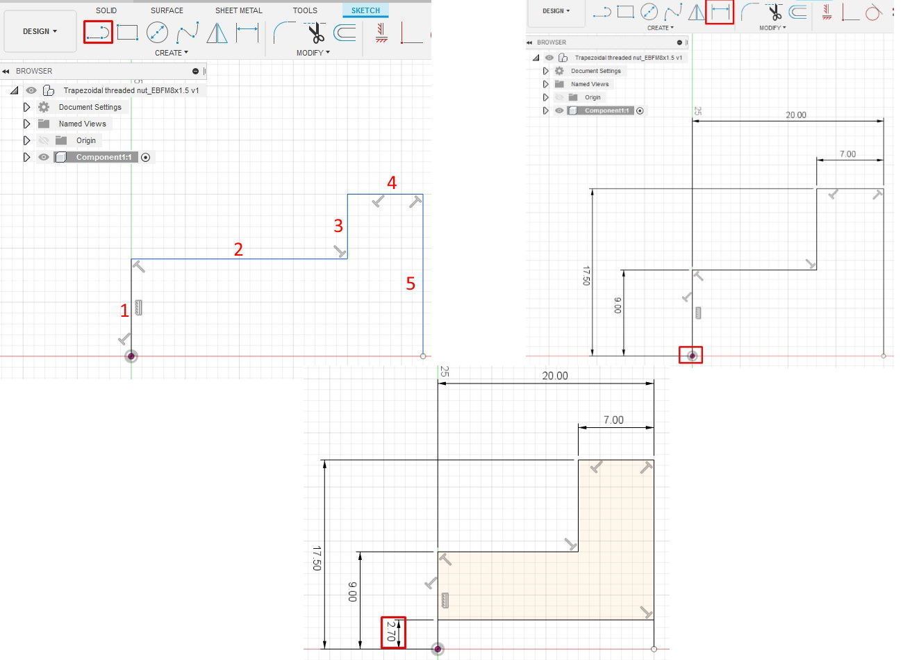
- Draw the Trapezoidal threaded nut sketch - starting from the point of origin draw lines from 1 to 5
- Place dimensions and don’t forget to place dimensions for the diameters beginning from the point of origin, otherwise your sketch can change its form unpredictably.
- The height of the tooth is vary from 1.27 to 1.3 mm – accordingly we must place line 6 which is lays 2.7 mm away from the center.
- Click Finish Sketch
After your sketch is finished you can create some bodies with the Model workspace’s construction tools. Most used are Extrude, Revolve, Sweep and Loft which you will find in the Create menu. When you will use one of them the dialog box appears and you can choose some options like Join, Cut, and Intersect. The Join will fuse bodies together, Cut subtracts one body from another, and Intersect leaves the overlapping parts of multiple bodies.
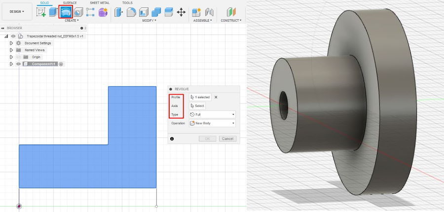
We will use the Revolve tool to create our Trapezoidal threaded nut. Revolve rotates a sketch around an axis and with this tool you can create some parts like bearings, pulley, couplings etc.
Select the sketch to revolve and then select the axis to revolve it around.
Creating Thread
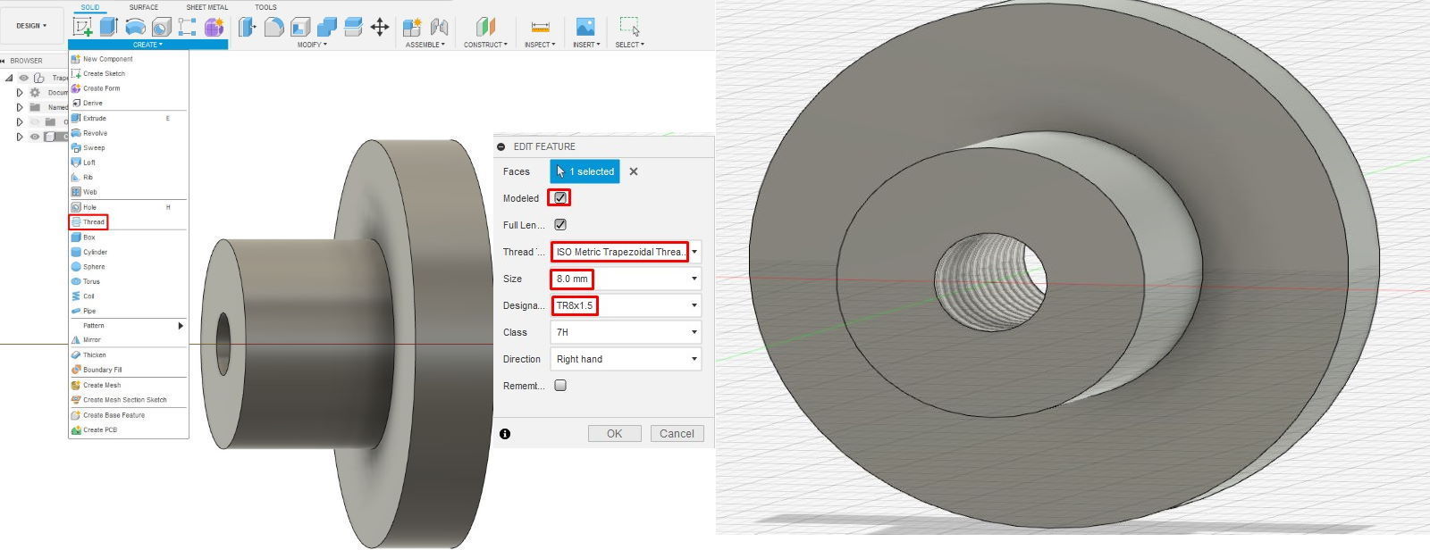
Fusion 360 gives you a tool that lets you skip all of that. The Thread tool contains a library of just about every thread commonly used today. All you have to do is to create a cylinder to put the threads on.
1. Rotate your model in the way that you can see the center hole
2. Select DESIGN > Thread
3. In the Thread dialog window select:
- Select the face of the center hole
- Then check Modeled to make the threads appear there. (If you leave the Modeled option unchecked, Fusion 360 will just store the thread information for a later technical drawing.)
- Because we want the threads to span the full length of the cylinder, check Full Length.
- Thread type – ISO Metric Trapezoidal Thread
- Size – 8 mm
- Designation – TR 8x1.5
Now we can place holes and perform some nice touches to our design.
Creating holes
- Rotate the model that you can see the back side
- Create a sketch and as a plane select back of the model
- Place one circle on the Y axis and dimension it according to the technical documentation
- Finish the sketch
We already learned how to use the Extrude tool and now we will use the Hole tool
1. Select Hole tool from the Design Panel
2. in the dialog window select:
- Placement – at the point and select center point of our sketch
- Extends – Through all
- Assign one more time the 3.5 mm diameter of the hole
3. Click OK
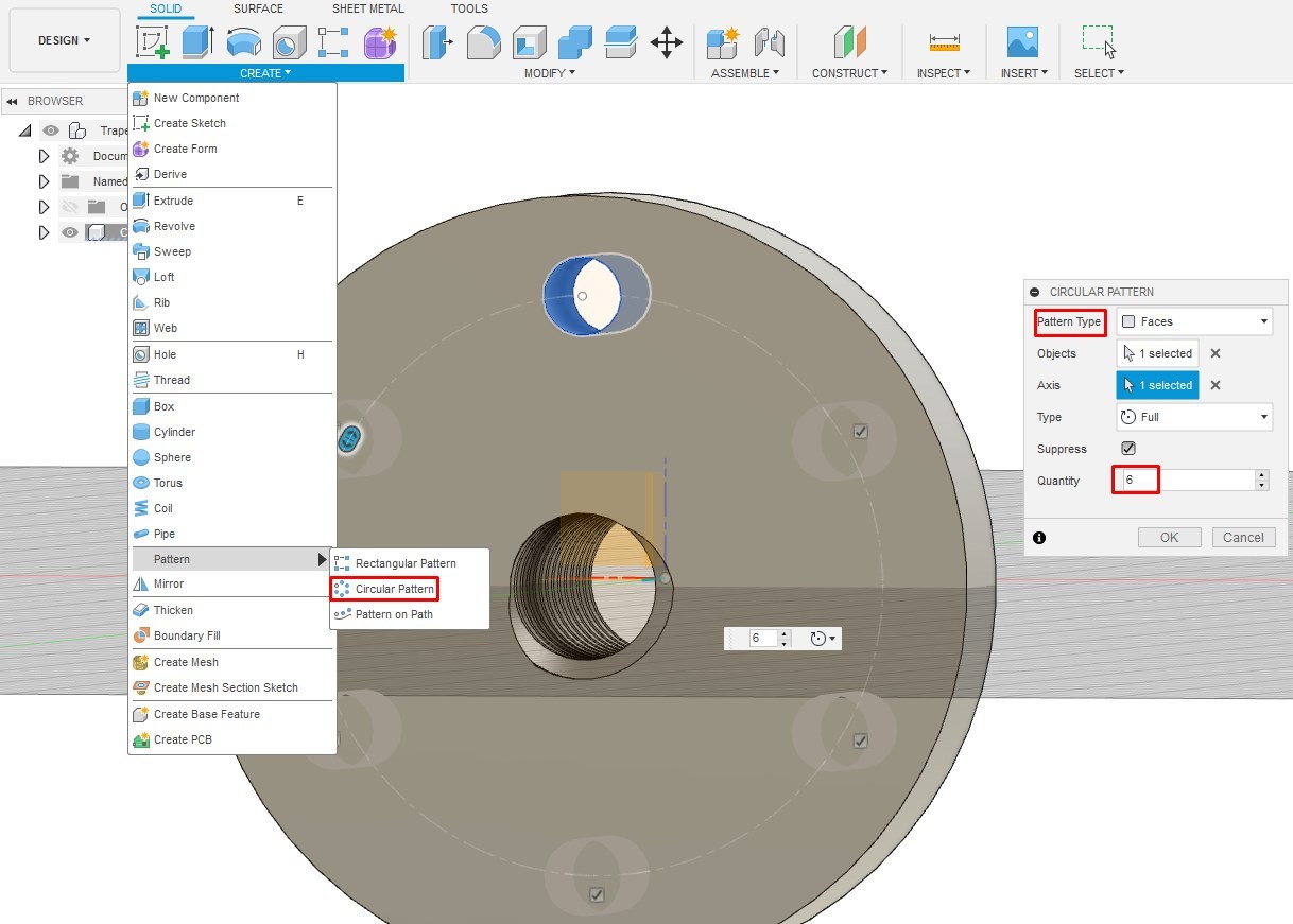
So next we can use the pattern to create 5 remaining holes. To do that Click CREATE > Circular Pattern, and then select the object to the pattern (hole face), the Y axis to revolve around, and the quantity.
After we have all important elements we can make some nice touches like Fillet and Chamfers. I placed a 0.5 mm fillet between two cylinders and three 0.5 mm chamfers on the edges of the threaded nut.
NOTE: In the chamfer dialog box you can select all three edges to apply the chamfer procedure and the same for the fillet. It will definitely increase your work flow speed.
Your model should now look like a real trapezoidal threaded nut with built-in threads. As a final step, give the screw’s tip a revolved cut to make it easier to insert
Assembly
I would recommend to save your parts / components in separate files – it will significantly simplify the assembly process and the creation of the Beal of Materials (BOM) for your project.
A component is a container which holds an object (like the 2020 profile) or multiple objects (like the NEMA stepper motor), and any other constriction elements which make up a part.
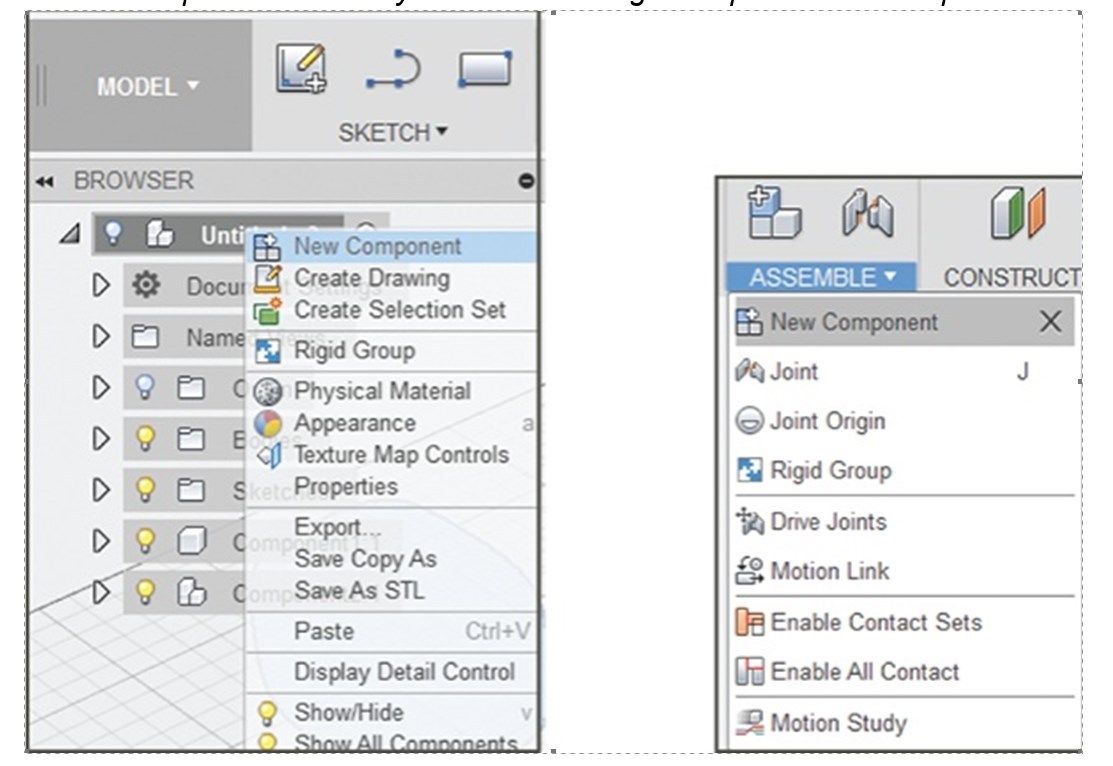
To create a component RK in the browser title field select New Component, or you can create an additional component in the assembly space by selecting ASSEMBLE > New Component in the Design Toolbar.
It is most important that with those two methods the complete parametric history will be stored inside the component, which will significantly simplify your work in the future when you decide to change or improve your design.
Create components before you start modeling it will preserve a complete timeline of your operations.
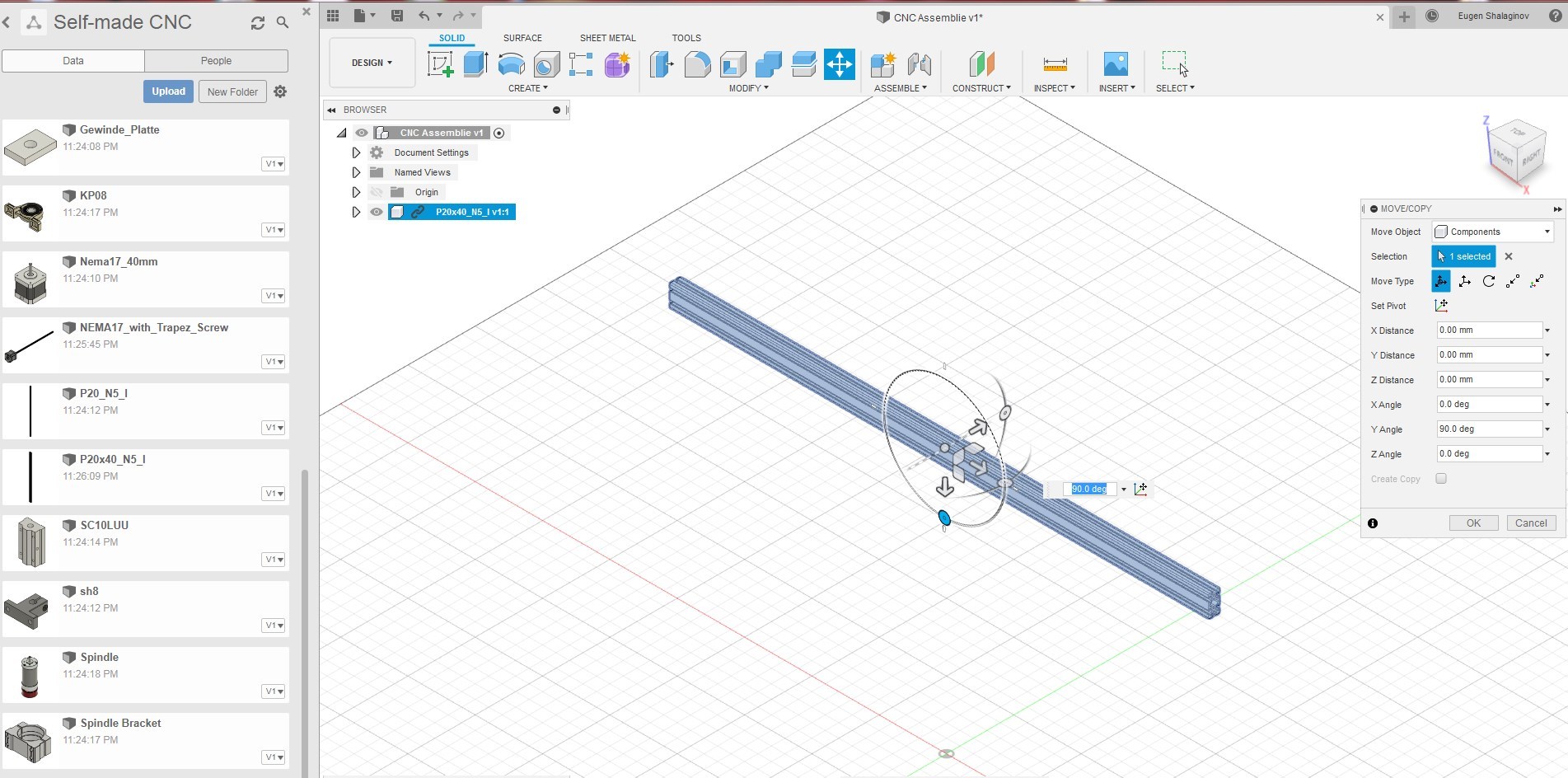
First of all we will create a new Project – we name it CNC Assembly I have uploaded some models of the aluminum profiles, NEMA motor, shaft holder, spindle etc.
You can use the same components for your project. Or you can download a STP model of different CNC parts from my GitHub repository.
https://github.com/EcoEngineering/Design-CNC-in-Fu...
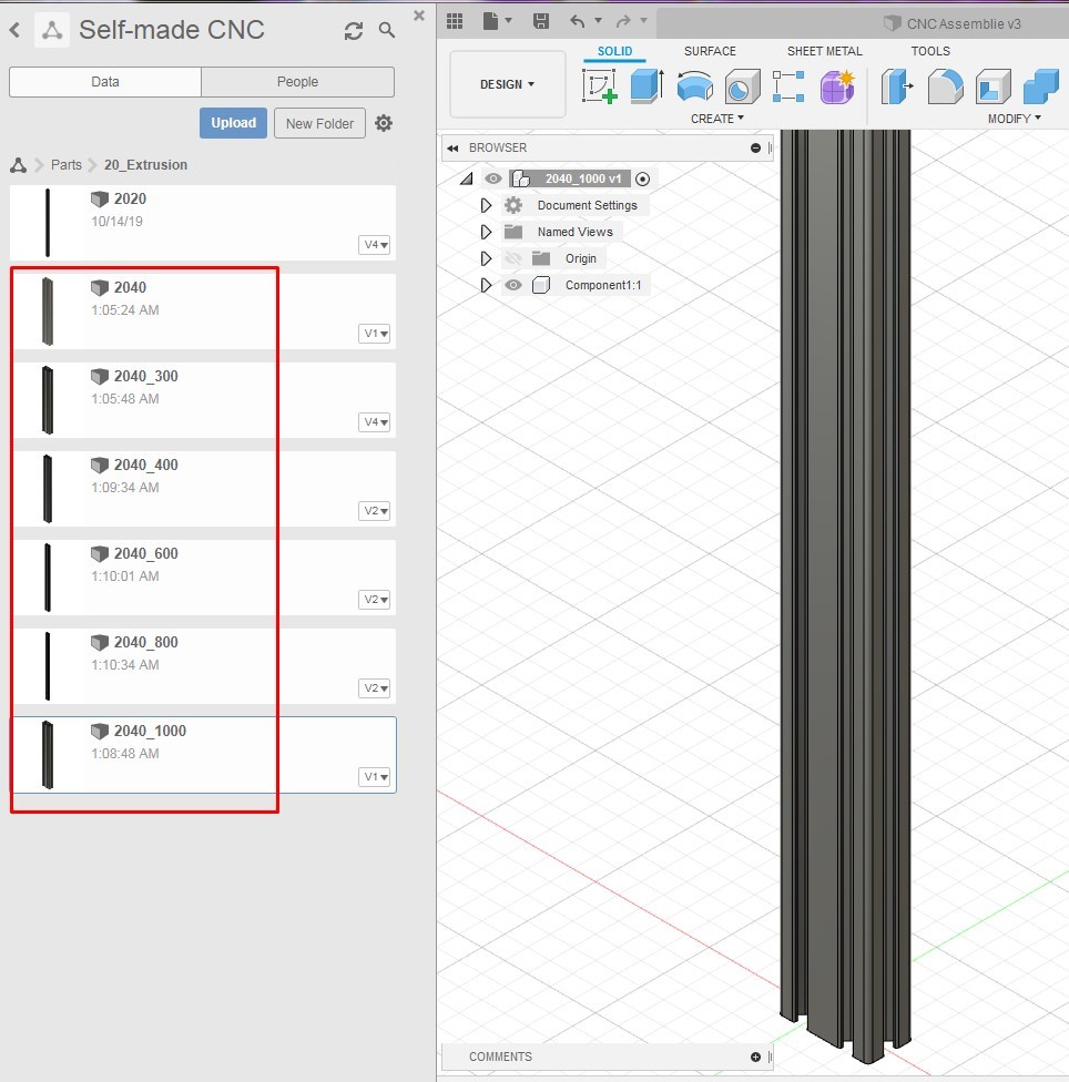
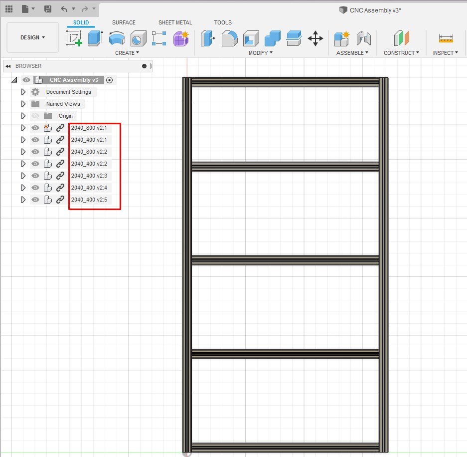
To simplify the assembly I made copies of my 2040 profile and then changed the extrusion length to 300 mm, 400 mm, 600 mm and 800 mm, or you can make parametrical model and change the profile length interactively.
Now I am able to drag parts with the required length in my project.
In the assembly you can move and rotate your part by using handle or typing dimensions in properties window – depending on your point of view different handle will appear.
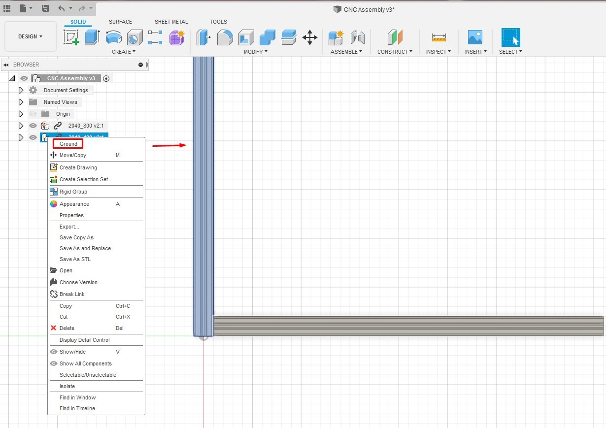
I have placed the first profile at the center point and grounded it (RK on the model in the browser – Ground) – it means that this profile can’t be moved and will be used as reference point.
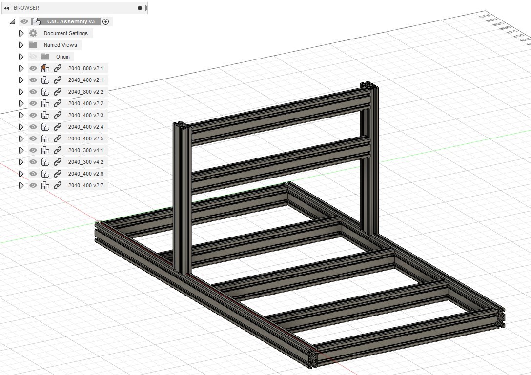
After that you can position all your components – play a while with different positioning functions to be familiar with it.
NOTE: The assembly is a big topic, so I will make another intractable related to the parametrization and assembly.
Making CNC
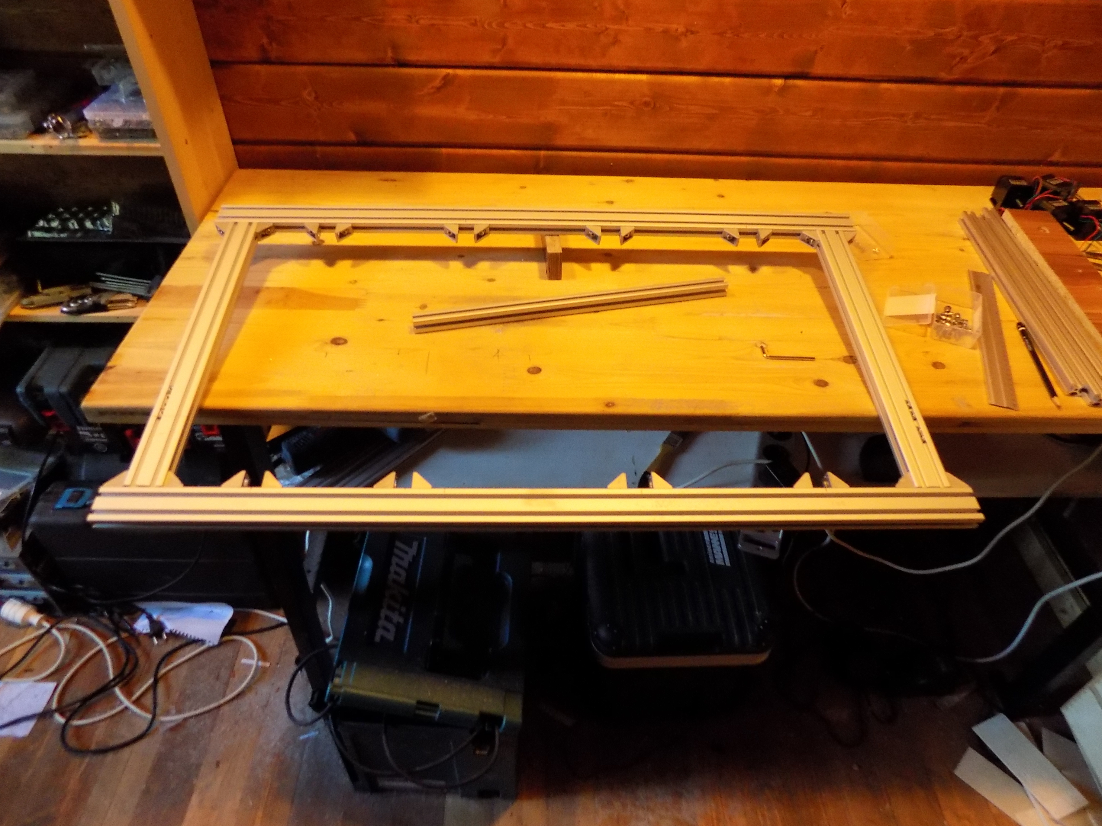
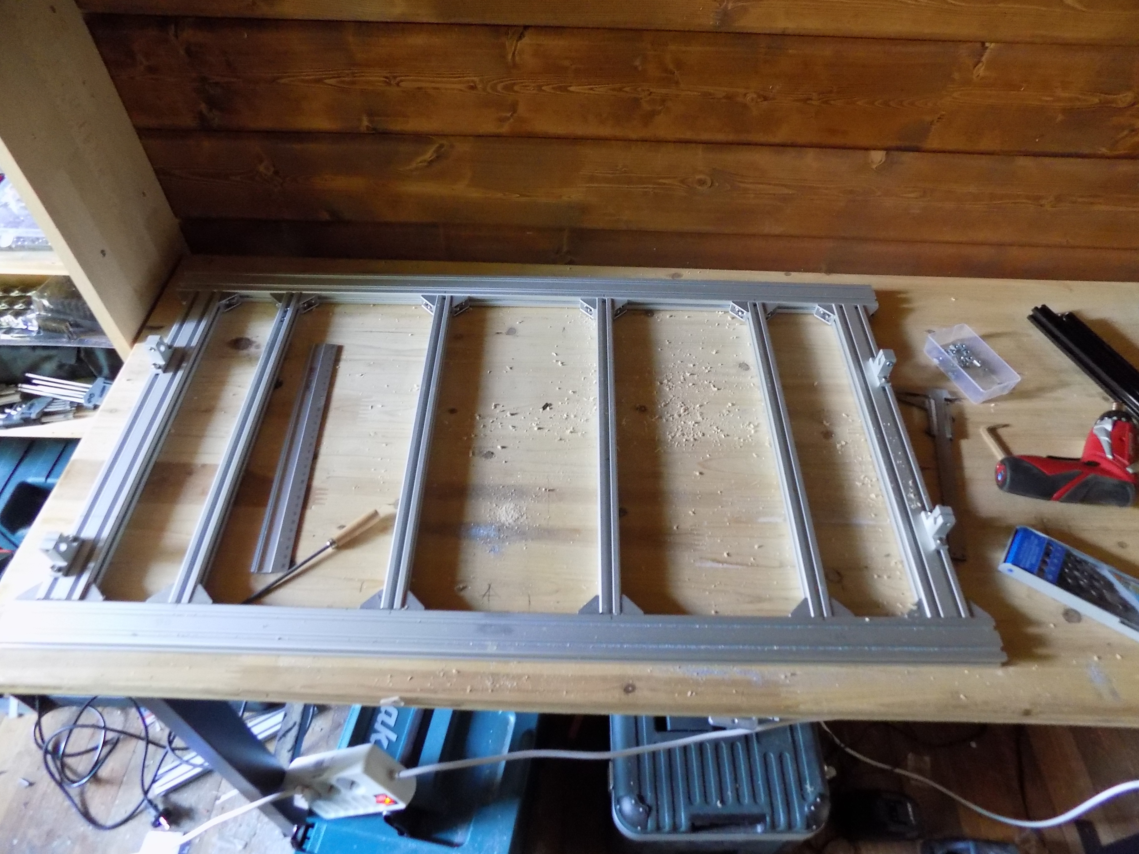
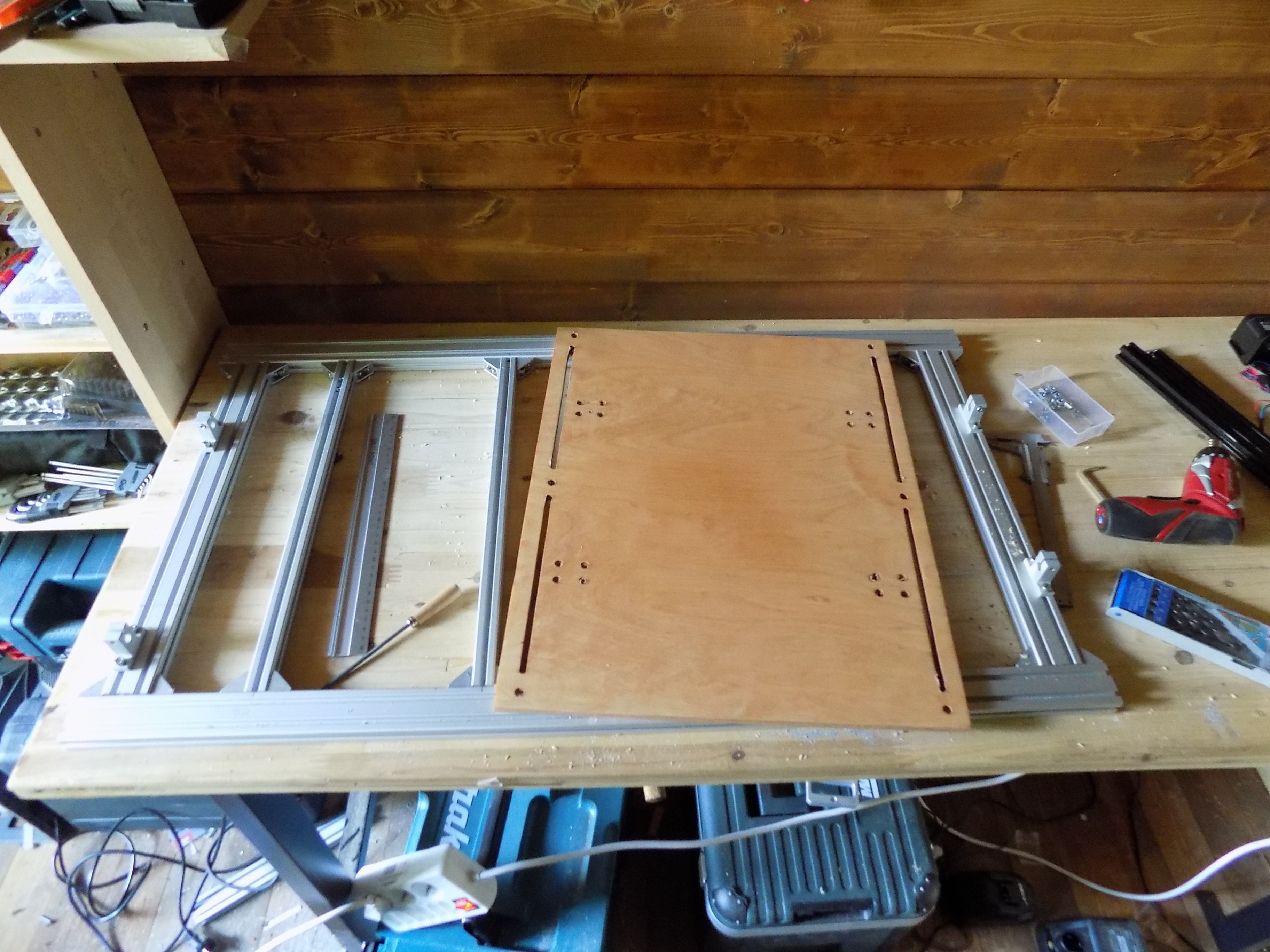
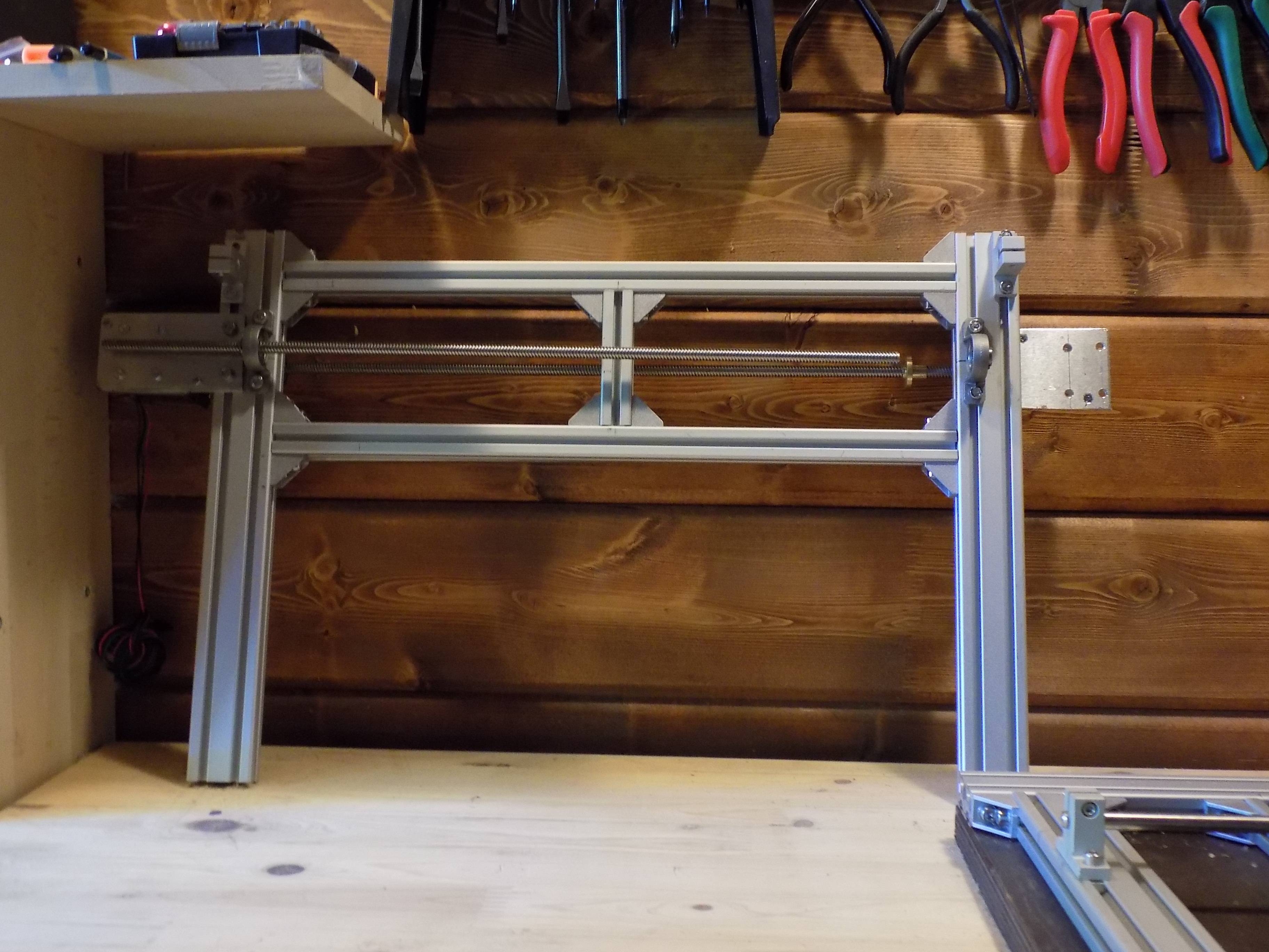
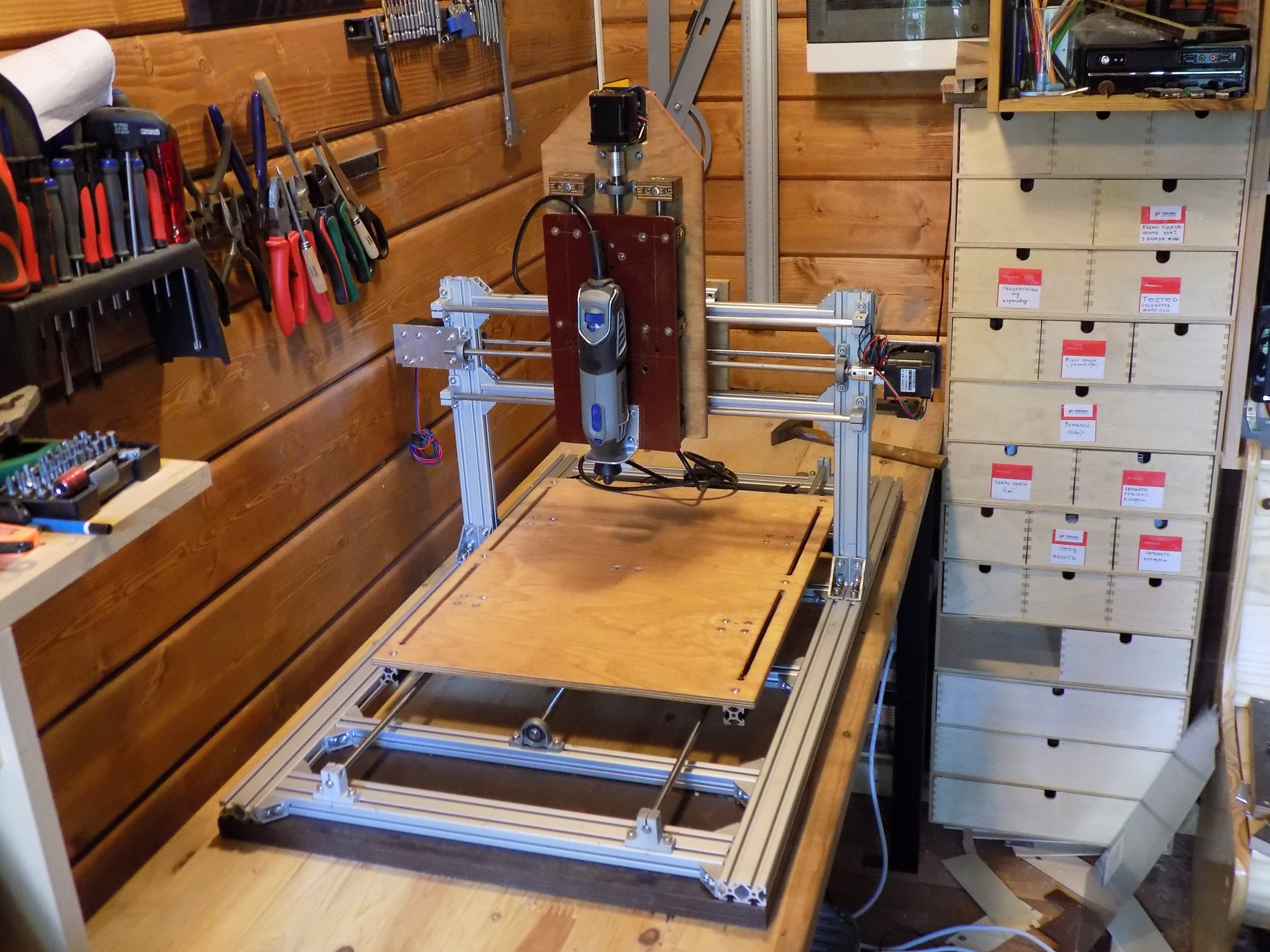
Fusion360 defines your creativity in a way that you can establish your CNC assembly and change its parts or size anytime and experiment with different parameters like profiles or sliders sizes etc. When you are eventually satisfied with your creation – then print BOM from Fusion, order components and have fun with making your own CNC.
Here some photos of my first self-made CNC.
NOTE: This CNC was designed for a “DREMEL” router, as a result a 2040 aluminum extrusion for the vertical support was more than enough.
If you would like to use a more powerful router with 500 W or 1.5 kW – then you should definitely design some kind of frame made of 2040 profiles or 10 mm aluminum plates for your vertical support.
Luckily, you can e change and upgrade your design in Fusion 360 easily.
You will find CNC models and parts in our GitHub repository.
https://github.com/EcoEngineering/Design-CNC-in-Fu...
Have fun with creating your own CNC.