Design a Cosplay Demon Horn for 3D Printing
by TimS124 in Craft > Costumes & Cosplay
8088 Views, 44 Favorites, 0 Comments
Design a Cosplay Demon Horn for 3D Printing

Drawing the Horns...
.jpg)
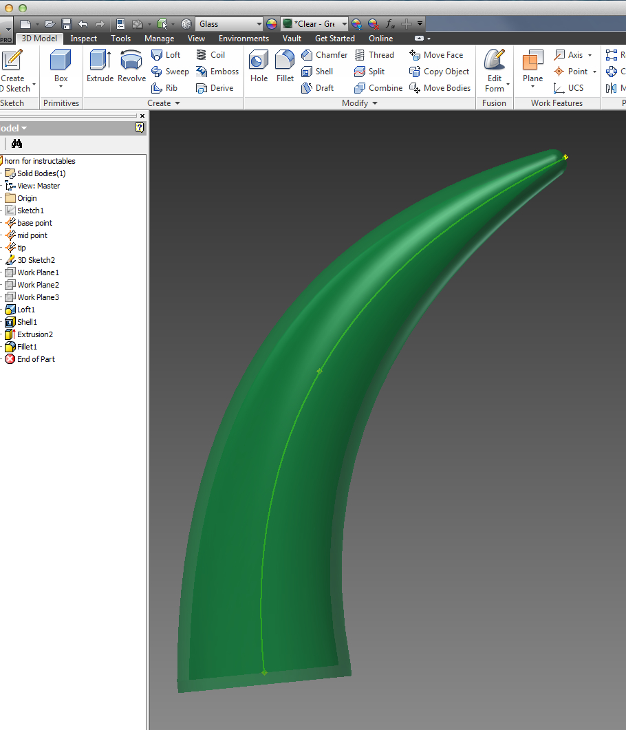
For those already familiar with Inventor, here's a very brief summary of how the horn was drawn:
- Create 3 grounded points, one each at x,y,z = 0,0,0 (base); 7mm,0,38mm (mid); and 30mm,0,70mm (tip)
- Connect the 3 points with a spline
- Create a work plane at each point (normal to the spline/line just created)
- Draw a circle on each work plane (base = 22mm diameter, mid = 16, tip = 3)
- Loft the circles
- Shell to 1.5mm wall thickness
- Fillet tip's 3mm circle at 1.5mm to round it over
- Create a separate part file with a 1.5mm thick, 22mm diameter circle (end cap)
- Create an assembly with the end cap at the origin, then mount the horn onto the end cap
- Export as a .stl file
Create 3 Grounded Points


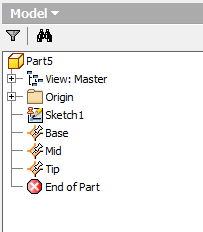
The two extra points simply allowed a little more control over the shape of the curve and the way the horn tapered. Those two extra points were between the middle and the ends (one point on each side of the middle roughly splitting the distance between the middle and each end).
To start drawing the horn's shape, create a new "part" in Inventor...this should automatically bring you into editing the first sketch (the "Sketch" tab along the top of Inventor's window should be active).
While having the initial sketch automatically opened is usually saves a tiny bit of time, but grounded points are not created within a sketch. Close the sketch by clicking on the "Finish Sketch" control. It's along the right hand side of Inventor's top ribbon. The first photo for this step is tagged to show the location of the "Finish Sketch" button.
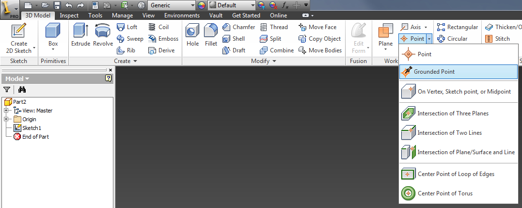
The second photo shows where to find the "Grounded Point" tool on the ribbon. Pop open the menu that it's in and click to activate that tool. You'll have to reselect that tool for each grounded point (total of three).
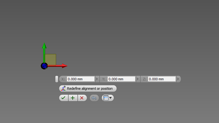
The Grounded Point tool needs an existing point to start with...we'll just use the origin that was automatically created by Inventor at 0,0,0. Click at the origin to place the base's grounded point at x,y,z = 0,0,0. Photo 3 shows this grounded point as it's being created.
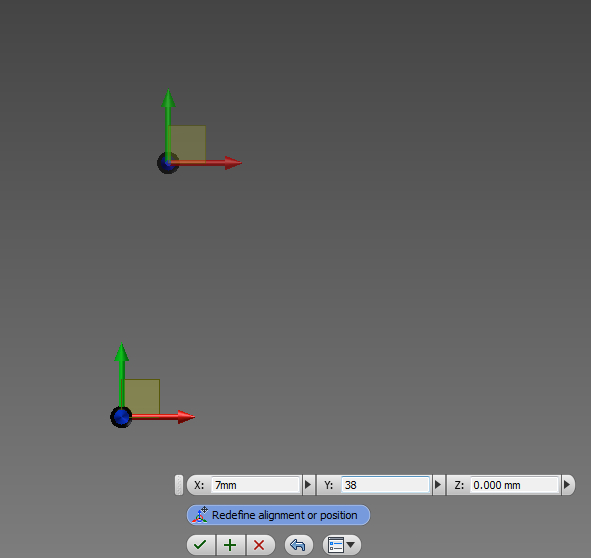
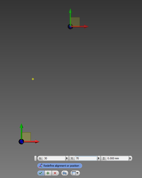
Select the "Grounded Point" tool again, click on the origin, and then click on the "Redefine alignment or position" button that's on the tool menu near where you're working (see Photo 4 if you're not certain where to click)...that will let you enter exact coordinates for X, Y, and Z...enter 7mm, 38 mm, and 0mm, then click the green check mark to accept those values.
My part file was set as millimeters by default, so I skipped entering the units in some of the screen shots. If your part file is set to inches, you can override that by always entering the desired units.
Select the "Grounded Point" tool again, click the origin, click "Redefine alignment or position", and this time, enter values for X,Y,Z = 30mm,70mm, and 0mm then click the green check mark to accept those values. Photo 5 shows this point being created.
Photo 6 shows all three grounded points after they've been created.
By default, the new grounded points you've created will show up in Inventor's browser history as "Work Point 1", "Work Point 2", and "Work Point 3". Rename those to "Base", "Mid", and "Tip" to make later steps easier to follow. Photo 7 shows those points after I renamed them in my part's browser/history.
Save your work.
Connect Grounded Points With a Spline
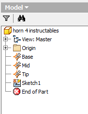
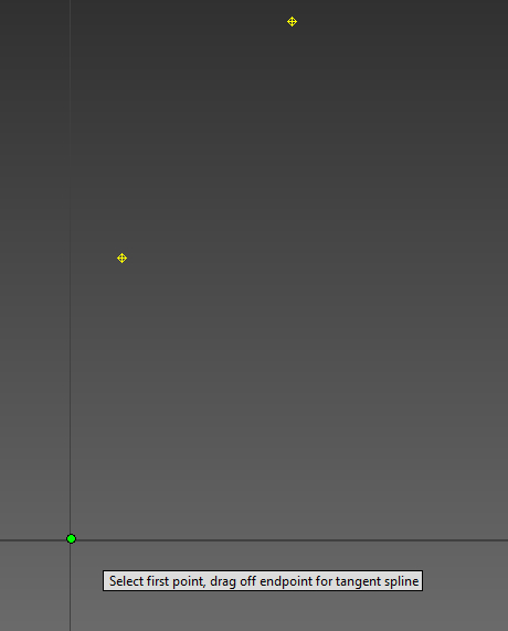
The sketch has to appear AFTER/BELOW the grounded points in order to be able to use them while editing the sketch. Just click on the sketch's name and drag it to the bottom of the browser/history section. It should look like Photo 1 when you're done.
Open that sketch by double-clicking on it...we can't get to the "Spline" tool unless we're editing a sketch...
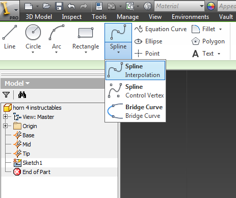
This step requires the "Spline" tool which can be found towards the left edge of the ribbon at the top of Inventor's window..see Photo 2 if you're having problems finding this tool.
Once you've selected the correct Spline tool, click on the "Base" point, then the "Mid" point, and then the "Tip"...then click the green check mark on the tool's contextual menu (NOT the "Finish Sketch" green check mark along the top of the screen!!!). You can also just hit the ENTER key after clicking all three grounded points.
After completing the Spline tool's task, click "Finish Sketch" in the ribbon along the top of your screen.
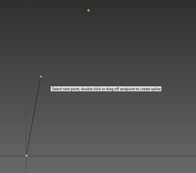
Photo 3 shows the Spline tool being used to click on the Base point. Photo 4 shows the Spline tool being used to click on the Mid point...notice the black line connecting the two points...that's the spline we're creating and after a third point has been added, it will be curved instead of straight.
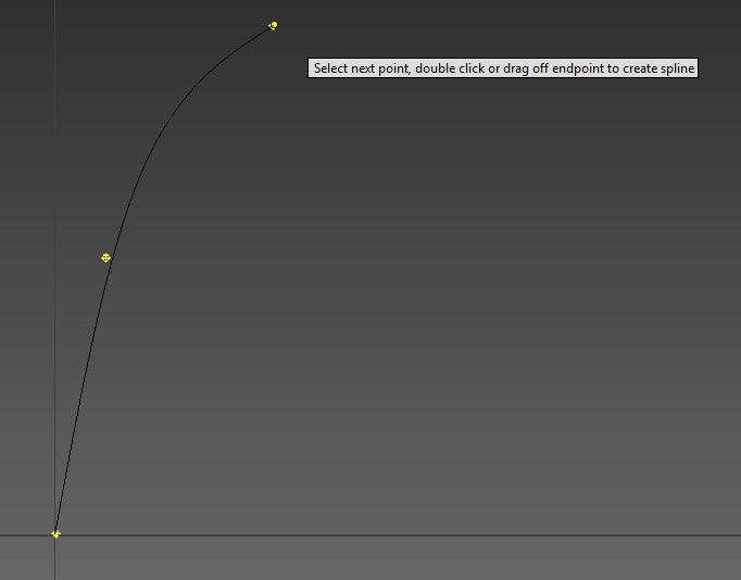
Photo 5 shows the Spline tool after the Tip point has been clicked...notice that the black line no longer runs exactly through the Mid point...that's a side effect of the interpolation blending the original straight line into a curve that flows from the Base, through the Mid and into the Tip. My original design had two additional points to allow more control over the shape of the line.
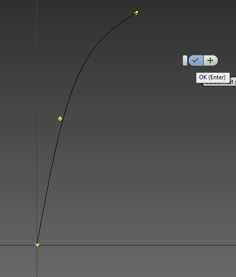
Photo 6 shows the tool menu's green check mark that lets you complete the tool's operation...or you can hit the ENTER key. The floating tool menu never seems to be where I expect it, though you can drag it around the screen. It wasn't in the prior screen shot so I moved it over for this photo...
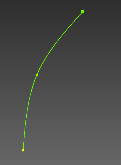
Photo 7 shows the completed spline.
Create a Work Plane at Each Point


The "Loft" tool will connect and blend those circles along the spline's line in a later step...but we can't create the circles properly along the spline line unless we have a "work plane" defined at each point.
If you forgot to close the sketch after the prior step, you'll need to do that now. The tool we'll need in order to create the work planes is only available while NOT editing a sketch.
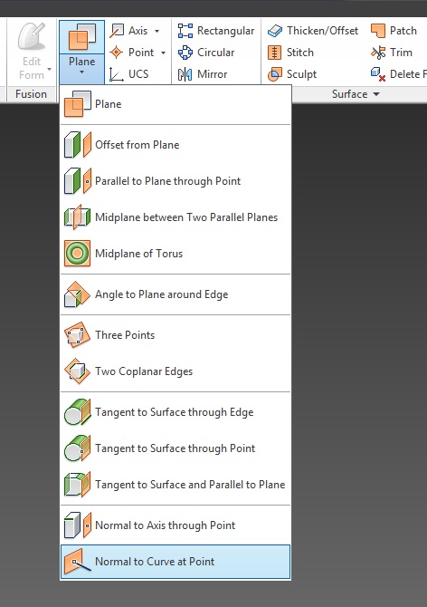
Along Inventor's tool ribbon, find the section for "Work Features" and click on the "Plane" tool's pop out menu. At the very bottom, there's a tool called "Normal to Curve at Point". We'll use that to create a work plane at each of our three grounded points (Base, Mid, and Tip).
If you've never used this tool, it's best if you look at Photo 2 as you work through the creation of the work planes. Photo 2 is a composite of the changes you should see on-screen as you use this tool to create the first (base) work plane.
On the left is the green line...I hadn't click anything yet and you can see the tool's help is telling me to select either a curve or a point...PICK THE CURVE!
The second panel shows the green line has turned white because the mouse pointer is on top of it. I had NOT yet clicked on the line...that's the third panel. Merely pointing at the line turns it from green to white so you know which line the tool intends to work on.
Click the curve...which brings us to the middle (third) panel in Photo 2. The tool's help test says the same thing and since we've already clicked on a line, this time we'll click on a point...the Base point. When you move the mouse over the base point, a short yellow line is drawn through the point...that's the work plane that will be created once you click.
If you haven't already clicked on the Base point, do that now. The spline line turns back to green. The yellow line shows up in white with circles on the end because my mouse was still sitting over the Base point when I took the screen shot. Move your mouse away and the short line should turn yellow to show the work plane you just created.
Select the "Normal to Curve at Point" tool from within the "Plane" pop out (under "Work Features" in the tool ribbon). Click on the curve (anywhere), then click on the Mid point. Photo 3 shows the step-by-step progression for creating this work plane (from left to right, same sequence as described for the Base point's work plane). It's much faster to just use the tool than to explain it...
Select the "Normal to Curve at Point" tool from within the "Plane" pop out (under "Work Features" in the tool ribbon). Click on the curve (anywhere), then click on the Tip point to create its work plane.
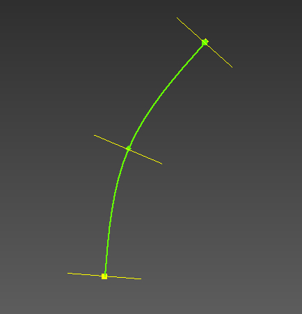
Photo 4 shows what your drawing should look like after creating all three work planes.
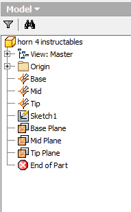
To make it easier to follow later steps, I suggest taking a minute to rename the work planes in the browser/history section to match the names in Photo 5. By default, in your drawing, they're likely just "Work Plane 1", "Work Plane 2", and "Work Plane 3".
Draw a Circle on Each Work Plane
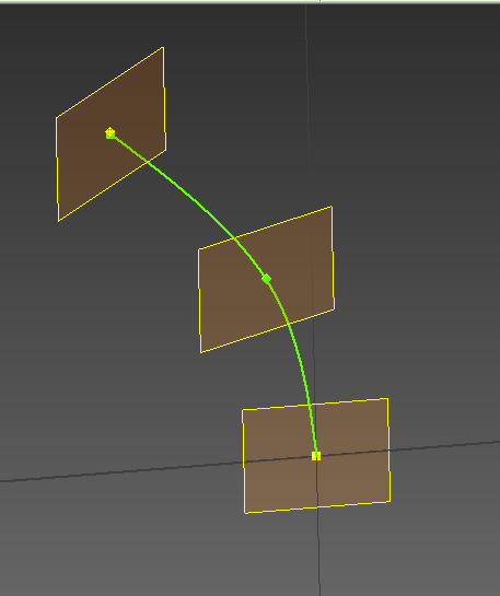

If you use the view cube to tilt your drawing so that the work planes are visible as squares instead of thin lines, the rest of this step will be much easier! Photo 1 shows how I've oriented the drawing to illustrate the rest of this step. Don't get too picky about lining yours up to exactly match mine...as long as you can see the work planes and the grounded points, you'll be fine.
Right click on the Base Plane in the Browser/History section, then select "New Sketch" to create a sketch on the Base plane.
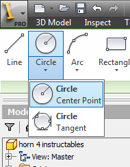
When you create a new sketch, Inventor opens it for editing...so, go ahead and draw the circle for the horn's base. Pick the "Circle" tool from the "Draw" menu...use the "Center Point" version of the Circle tool. Click on the Base point to place the circle's center, then just type in the desired circle diameter (22mm) and hit ENTER.
Photo 2 shows where to find the center point version of the Circle tool.
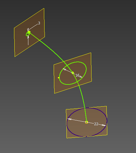
Photo 3 shows the progression of steps for creating the circle. The left panel shows the tool prompt prior to clicking on the Base point. The second panel from the left shows the tool prompt after I click on the Base point. The third panel shows the size I typed in (but I had not yet hit ENTER when I took that part of the screen shot). The fourth panel shows the results after hitting ENTER on the circle diameter that I entered.
Click "Finish Sketch" to close the sketch.
Right click on the Mid Plane in the Browser/History section, then select "New Sketch" to create a sketch on the Mid plane.
Pick the "Circle" tool from the "Draw" menu...use the "Center Point" version of the Circle tool. Click on the Mid point to place the circle's center, then just type in the desired circle diameter (16mm) and hit ENTER.
Click "Finish Sketch" to close the sketch.
Right click on the Tip Plane in the Browser/History section, then select "New Sketch" to create a sketch on the Tip plane.
Pick the "Circle" tool from the "Draw" menu...use the "Center Point" version of the Circle tool. Click on the Tip point to place the circle's center, then just type in the desired circle diameter (3mm) and hit ENTER.
Click "Finish Sketch" to close the sketch.
Photo 4 shows what your drawing should look like after creating all three circles.
Loft the Circles

If you want to turn yours off, right click on each work plane and toggle the "Visibility" setting in the pop up menu. You can turn them back on the same way if you need to work with them (while experimenting on your own with different horn shapes perhaps).
My computer glitched so I had to quit and relaunch Inventor. In the process, I reoriented the drawing (in case you were wondering why its position had suddenly shifted). It's important to be able to see each of the three circles created earlier (just as it was important to be able to see each of the work planes earlier).
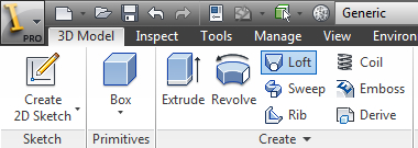
Photo 1 shows the location of the "Loft" tool...it's in the "Create" section of the tool ribbon (and his highlighted in blue in Photo 1).
Photo 2 shows the sequence of steps in using the Loft tool. Once you've activated the Loft tool, click on the Base circle...the circle should turn white when your mouse pointer is on top of it and once you've clicked that circle, its name should be automatically added to the list showing in the Loft tool's window.
Work your way up the horn, clicking the Mid circle to add it, then clicking on the Tip circle. As each additional circle gets added, the Loft tool should draw the in-progress shape.
If you're not getting the same results, check the other settings for the Loft tool that are visible in Photo 2...make sure your settings match what I've used.
Once all three circles have been added, click the "OK" button in the bottom left corner of the Loft tool's window.
Hollow Out the Horn

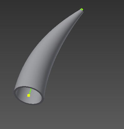
The Shell tool needs two critical pieces of information:
- Which surface it's going to remove.
- Desired thickness of the remaining walls.
Photo 1 shows where to find the Shell tool. That tool sits just left of the middle of the "Modify" section of Inventor's tool ribbon.
Active the Shell tool, click on the underside of the horn's base (you might need to reorient your view of the horn in order to expose the base), then type in the desired wall thickness (1.5mm), and hit Enter.
Photo 2 shows the horn from slightly below...the green spline line is once again visible since the majority of the base vanished during the shell operation. We can see though that the horn is now hollow...
Round Over the Tip
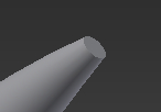
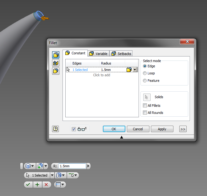
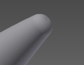
Move your mouse pointer so that it touches the Tip circle we drew earlier...the circle will turn white when the mouse is on it. Right-click and pick "Fillet" (or, pick the "Fillet" tool from the "Modify" section of the tool ribbon).
Use a value of 1.5mm for the fillet and make certain your other settings shown in Photo 2 match mine...
Click "OK" or hit ENTER to apply the round over and your tip should now look like Photo 3.
Now would be a good time to hit SAVE in Inventory again.
Plug the Bottom Hole...
I'm going to create a separate piece for the end cap. It's much easier to walk you through the steps and it simplifies slicing the horn for 3D printing. When the Spline tool connected our three grounded points, the resulting line left the Base work plane several degrees off from the most parallel axis. That will make it tedious to place properly in some slicing applications.
Plus, we had to create the horn laying on its side but it's better/faster/easier to print it standing up. Creating a separate end cap that is oriented the way we want to print the horn, then attaching the horn to the end cap as an Inventor assembly, will solve all those problems.
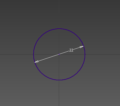
Create a new part file and use the circle tool to create a 22mm diameter circle that's centered on the origin, then click "Finish Sketch". Photo 1 shows the end cap I drew...
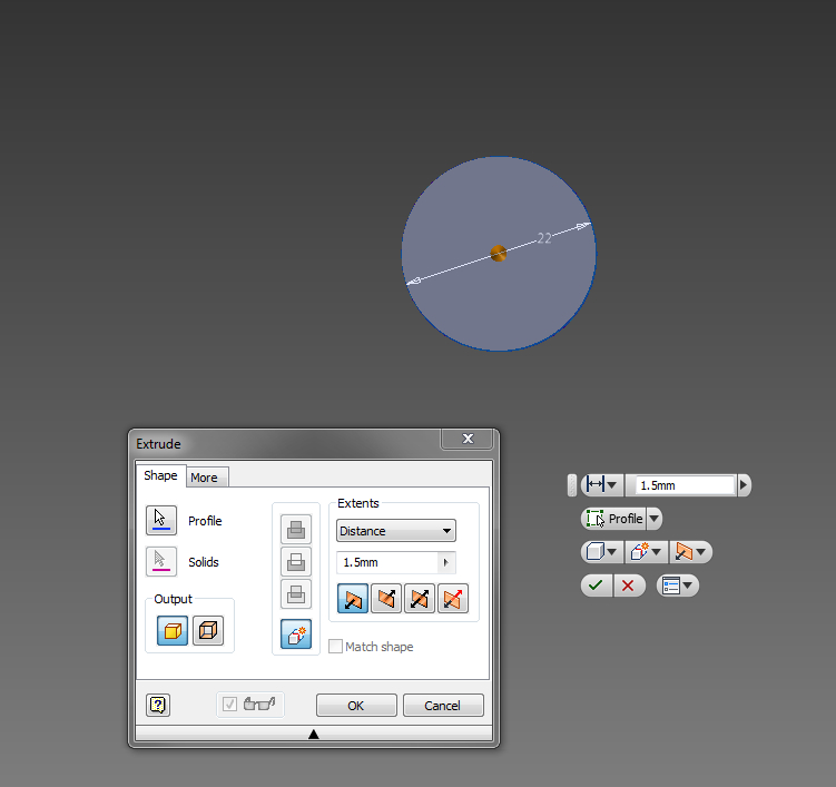
Click on the Extrude tool or right-click on the edge of the 3mm circle you just drew and pick "Extrude") and set the extrusion distance for 1.5mm, then hit ENTER. Photo 2 shows my extrusion in-progress.
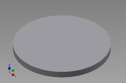
Photo 3 shows the completed extrusion position near the X/Y/Z axis indicator. Notice that the end cap's thickness is in the Z axis.
Save the end cap to disk.
Bring the Pieces Together
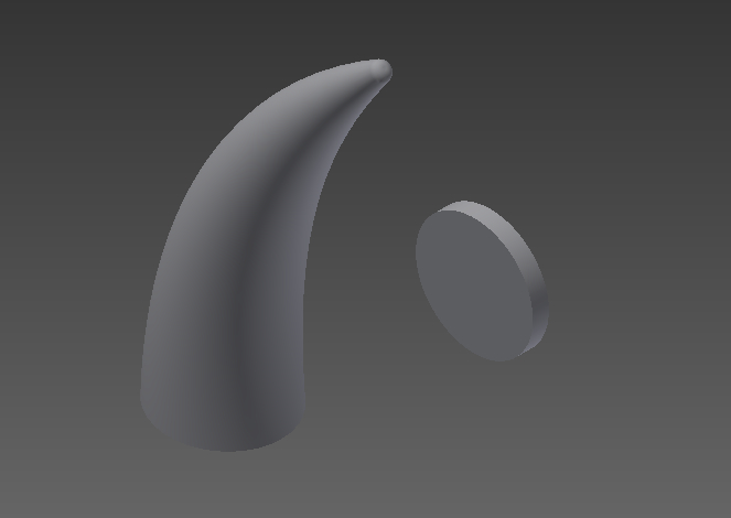

By default, one copy of the end cap will automatically be placed at the assembly's origin. Any clicking that you do will add additional end caps...so just hit the ESCAPE key to stop the Place tool.
Select the Place tool again to select the part file that contains the hollow horn. Click just one time to place only one copy of the horn into the assembly. Hit the ESCAPE key to stop the place tool.
Your drawing should look roughly like Photo 2...just one end cap and only one horn. Notice that the horn is standing up while the end cap is facing sideways. No worries...Inventor will do all the heavy lifting (thinking?) required to get these two pieces lined up properly!
Select the "Assemble" tool from the "Position" section of the tool ribbon. Photo 3 shows where to find that tool...
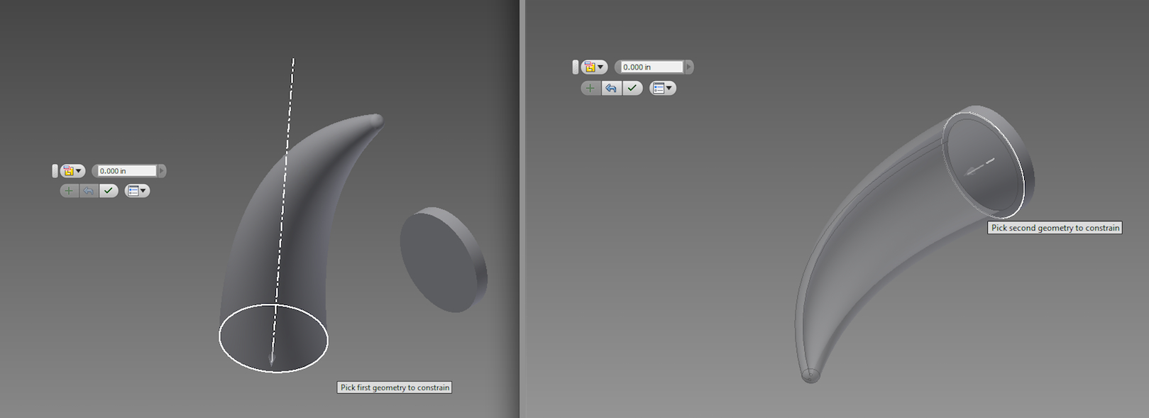
Make sure it's set to "Automatic" (there's a pop out menu showing in Photo 4, to the left of the field for entering a distance).
Move the mouse pointer over the bottom of the hollow horn until the 22mm diameter Base circle is highlighted (left panel of Photo 4) and click one time.
As soon as you've clicked, your mouse starts dragging the horn around trying to connect it to something/anything...move the mouse onto the face of the end cap...the horn will snap into a variety of possible positions as Inventor tries to guess what you want.
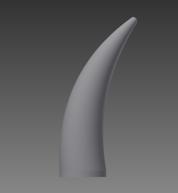
I found that moving the mouse near the bottom of the end cap's face positioned the horn to the left. That meant the horn was extending into the positive Z axis which is what I want for easy printing. Negative Z would also work since you can turn it around in the slicing software later...but why not just get it the way you want it here.
Once the horn is situated the way you want relative to the end cap, click the mouse to place the horn. Hit ENTER to put away the Assemble tool.
Save your assembly file.
Export the Assembled Horn for Slicing...
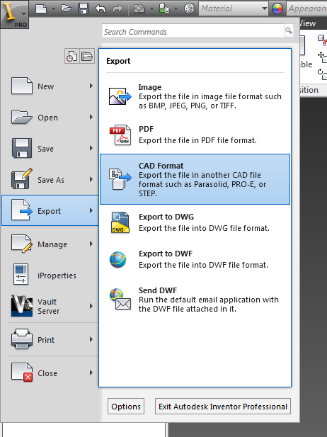
In the upper left hand corner of Inventor's main window, there's a copy of its colorful icon (the big yellow capital letter I)...click on that and move your mouse to the "Export" options.
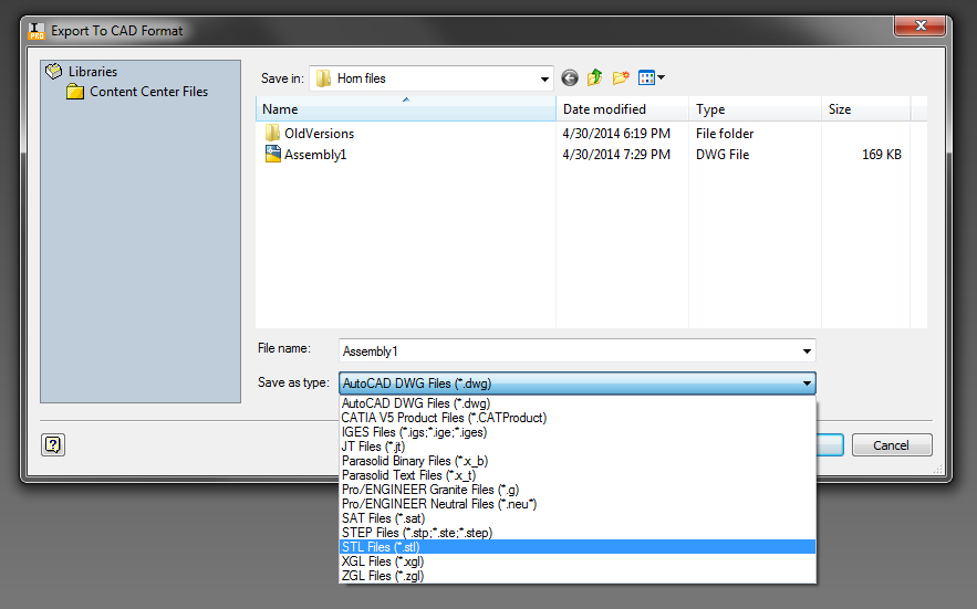
Within the Export options, select "CAD Format". I know it doesn't list .stl there, but that is where .stl is hiding... Photo 1 shows the details of the Export menu's choices.
Selecting "CAD Format" brings up a file save window that lets you choose from a wide variety of formats...Photo 2 shows the pop up menu's choices. The .stl choice is nearly at the bottom. Pick .stl, give your export file a name and save it to disk.
Go Print Your New Horn...
I've printed this design on at least three different brands of 3D printers. The directions are basically the same...so I'm going to make this part very generic. The horns print fine on Affina's UP! and the MakerBot Replicator at TechShop. I've also printed them on a Lulzbot TAZ 3. Different slicing and printer control software is recommended for different printers...use what works for the printer you'll use.
For your first print, I suggest printing it coarsely...thicker layers....to reduce the print time. You may want to tweak the shape/size of the horn. There's no point in printing at the smoothest (and therefore slowest) option until you're confident the shape/size is what you want.
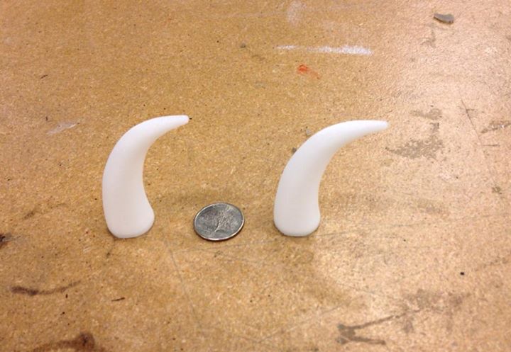
Photo 1 shows a pair of horns with a US Quarter between them to give a sense of scale. These were printed at TechShop San Jose on one of their MakerBot printers. Print time for each horn was about 25 minutes plus warmup time for the printer's bed (these are printed in ABS so a heated bed is important).
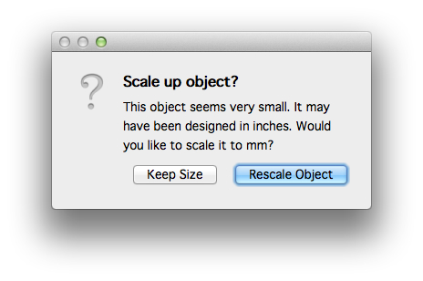
Dropping the horns.stl file into MakerBot's slicing app produces a warning that the object is very tiny and suggests the problem was that the file was designed in inches. Whatever...just hit "Rescale Object" and it'll all just work out. I'd swear I had my file set to millimeters... :-) Photo 2 shows the warning that MakerBot's software posted (along with the button to easily fix the problem).
I've printed these with and without support. If you use a raft under them, you'll likely have to print them with support turned on. My TAZ's heated bed, without rafting, grabs ABS really well...so I can print without support and get very good results.
If supports are enabled, the inside of the horns likely will also contain support...so they won't be as light as they could be if support was left off. Try it both ways and pay attention as it prints to see if the inside is staying hollow (or at least use the sparest possible infill settings).
As for attaching these to your head during Cosplay...I've been told that fashion tape works unless it's hot enough outside to make your head sweat. Several other things have been tried but fashion tape is still the preferred choice. I keep suggesting that a drop of superglue would hold them on all day (and probably for much longer than that day)... :-)