Desclock - VFD IV-18 Clock


Desclock is a clock with some additional features that make it special. For the display, a VFD Tube has been used. They have a very special glow and look great. The list below summarizes the main functions that have been implemented so far.
Clock Highlights
- USB powered
- VFD IV-18 Display
- Automatic display brightness
- Temperature sensor
- Internal clock (RTC)
- Internet time synchronization
- User web interface for time and location configuration hosted by the ESP32
- Touchless commands (tap commands)
- 2 Taps for Time display
- 3 Taps for Temperature display
- 4 Taps for display on for 30 minutes.
- Automatic display off to preserve display lifespan
- 5 seconds automatic time display each 15 minutes
- Haptic feedback
- RGB LED

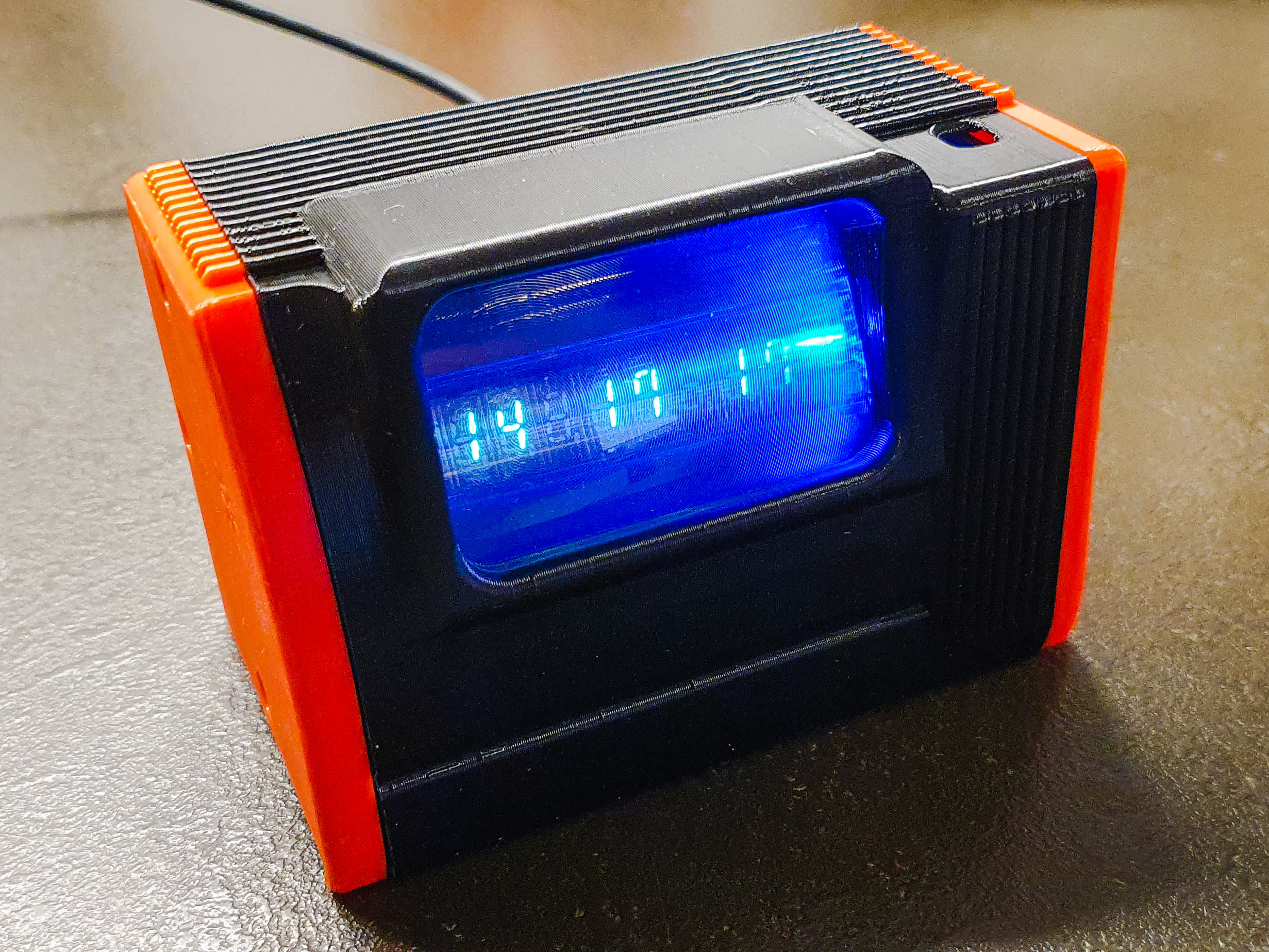
Desclock running
Schematics
From the schematic shown below the following sections can be seen:
- USB to UART
- Voltage regulator from 5v to 3,3V
- ESP32 module
- RTC Module
- RGB Led
- Temperature sensor
- Motor and its driver
- Microphone amplifier
- LDR for the automatic brightness adjustment
- VFD Driver
- DC/DC converter for the VFD tube

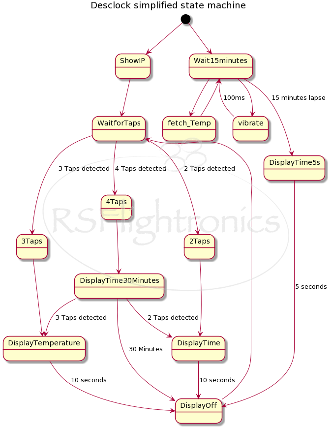
Simplified State Machine
Downloads
First Contact With VFD Displays


Desclock development
The journey started by getting some of these nice displays imported directly from Russia. They look just great! In this case, we are talking about a VFD-18 model.

IV-18 is a VFD (Vacuum Fluorescent Display) tube. It has 8 seven-segment digits with decimal point. The tube can display numbers from 0 to 9 in green color. The first segment has a thick dot on top of the '-' sign.
- Brightness: 400 kd/m2;
- Glow Current: 85 mA;
- Grid Current: 11 mA;
- Total segment Current (for one digit): 8 mA;
- Tube size: 18 x 115 mm (0.72"x 4.6");
- Digit height: 10.5 mm (0.42").
Preparing the VFD Driver


For this project, I used a specific VFD driver that helps to simplify the hardware. To be able to test this component I prepared a quick prototype setup.

Once this was done, I brought the VFD tube and the driver together

A lot of hours went into finding the right configuration to get a DCDC that was capable of providing the required voltage (around 50V) to drive the filament properly having as input just the 5V from the USB. Being able to simulate the booster accelerated the process a lot!

Time to Glow!
After several hours of programming and debugging, I got the display to show its first numbers :)

And after that, I was able to show more interesting information

Add More Glowing and Colors

Just because we can... I thought an RGB LED couldn't be missing on this project, right?


Level Up!
Since we are using an ESP32 as the brain of this project, we can go ahead and host a web page on it so we can configure our time zone and location and let the clock synchronize itself from the internet to display the local time and outdoor temperature.

Some Software Updates
VFD IV18 Clock with ESP32
VFD IV18 Clock with ESP32 Update #2
Moving to PCB
Once the prototype was working, it was time to move to the PCB design.


Chasis
For the chassis, I went with a self-carved wood variant


And also went for a steampunk style :)


Make It Smaller!
Once I was done with this clock, I thought it might be interesting to explore other variants and also something smaller. This is how I ended up embarking on another project with the small version of the IV18 tube, the IV21!


For this small variant, I designed a 3D-printed chasis