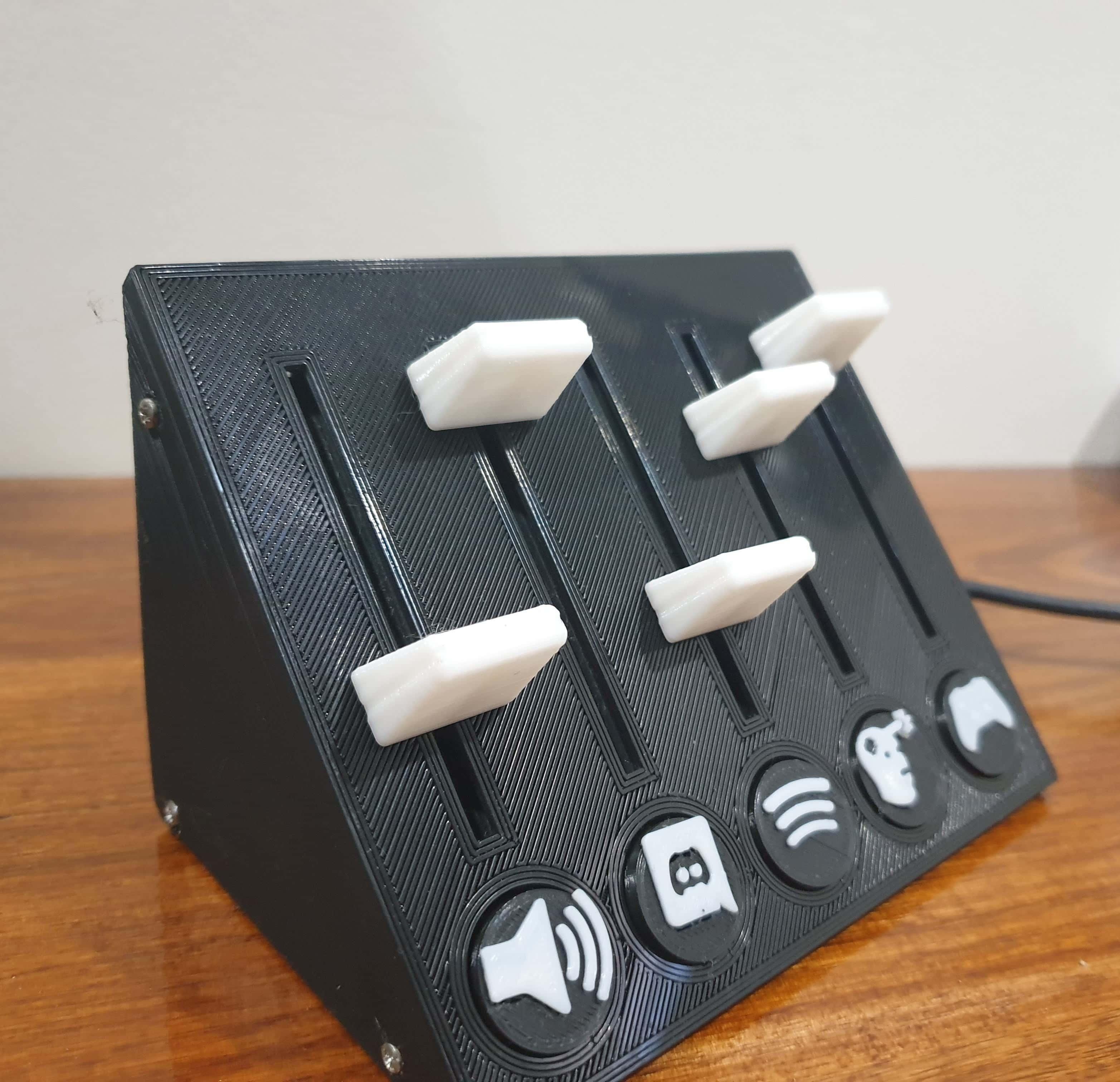
Deej Box - 5 Sliders
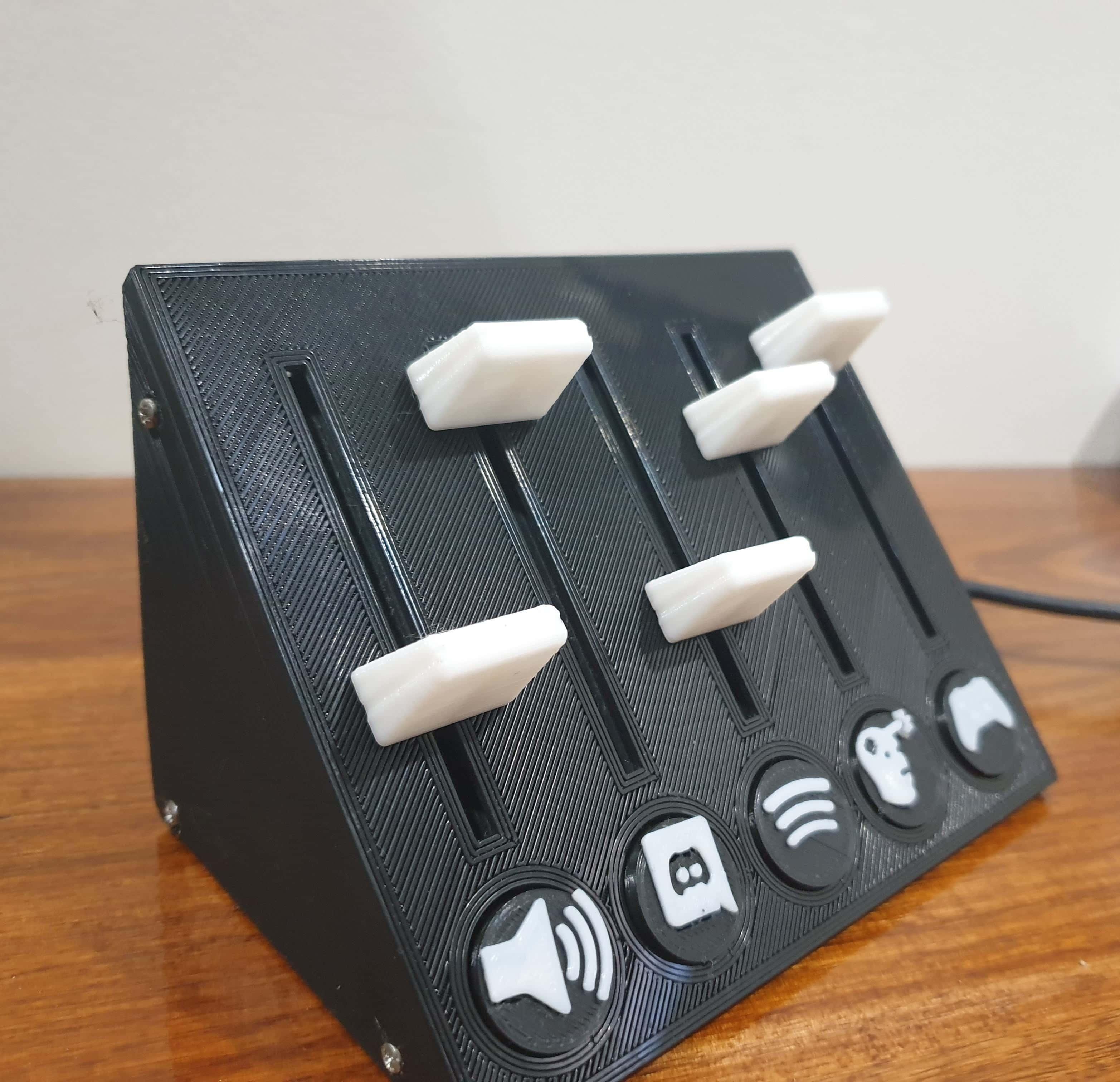
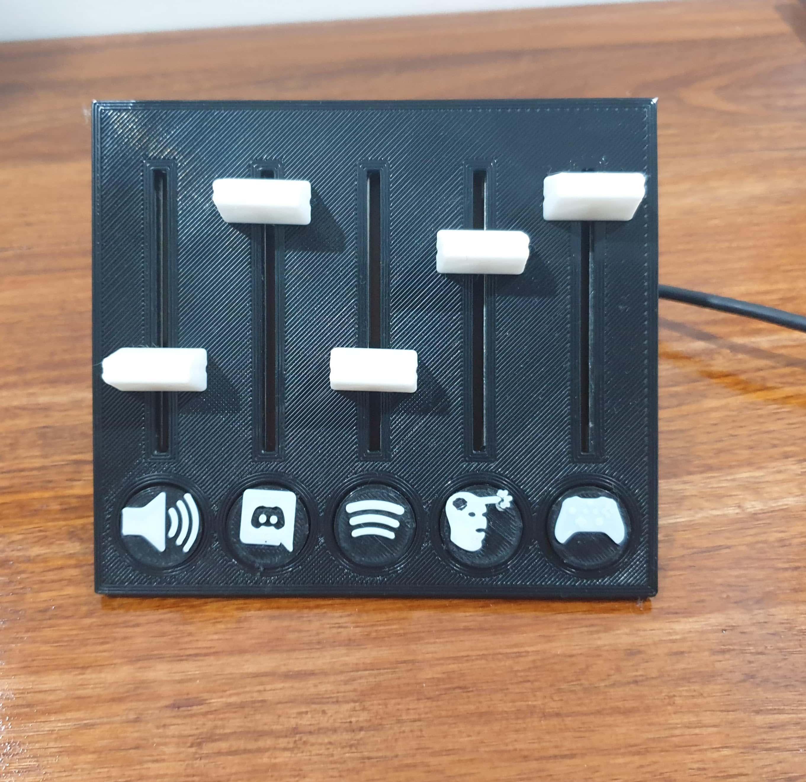
This is my take on the Deej project that allows you to control PC program volumes individually and is fully configurable to individual needs very easily. My design features 5 sliders with magnetic, swappable badges to identify each slider. It is constructed from 3 main 3D printed parts and features a clean faceplate, with screws only visible on the sides.
Supplies
- 20x M2 6mm screws
- Mini B USB cable
- Arduino Nano (or other board with 5+ analog pins)
- ~1m hookup wire (26AWG was used)
- 5x Linear Potentiometers - Used here
- 10x 5mmx1mm magnet discs
- 3D printed parts - STL's provided
- Soldering Iron
- Super glue
Print the Parts
Download all the STL files you will need for the creation of this project. Don't forget to follow this link to the knobs I used (but didn't design).
3D print all the parts needed for the build. I used the following settings:
- 0.2mm layer height (only the sleeve and knobs is visible so the other parts can be printed at a lower resolution if desired)
- 20% infill
- Supports enabled
- No raft for a nicer finish
- 102% scale for the knobs
- Pause at 4.5mm height for the buttons to swap filament for the two tone look
Note that the orientation you wish to print the parts in will depend on you build surface. I printed the sleeve face down on my glass bed to achieve the glossy, smooth finish you see.
Attach the Sliders to the Faceplate
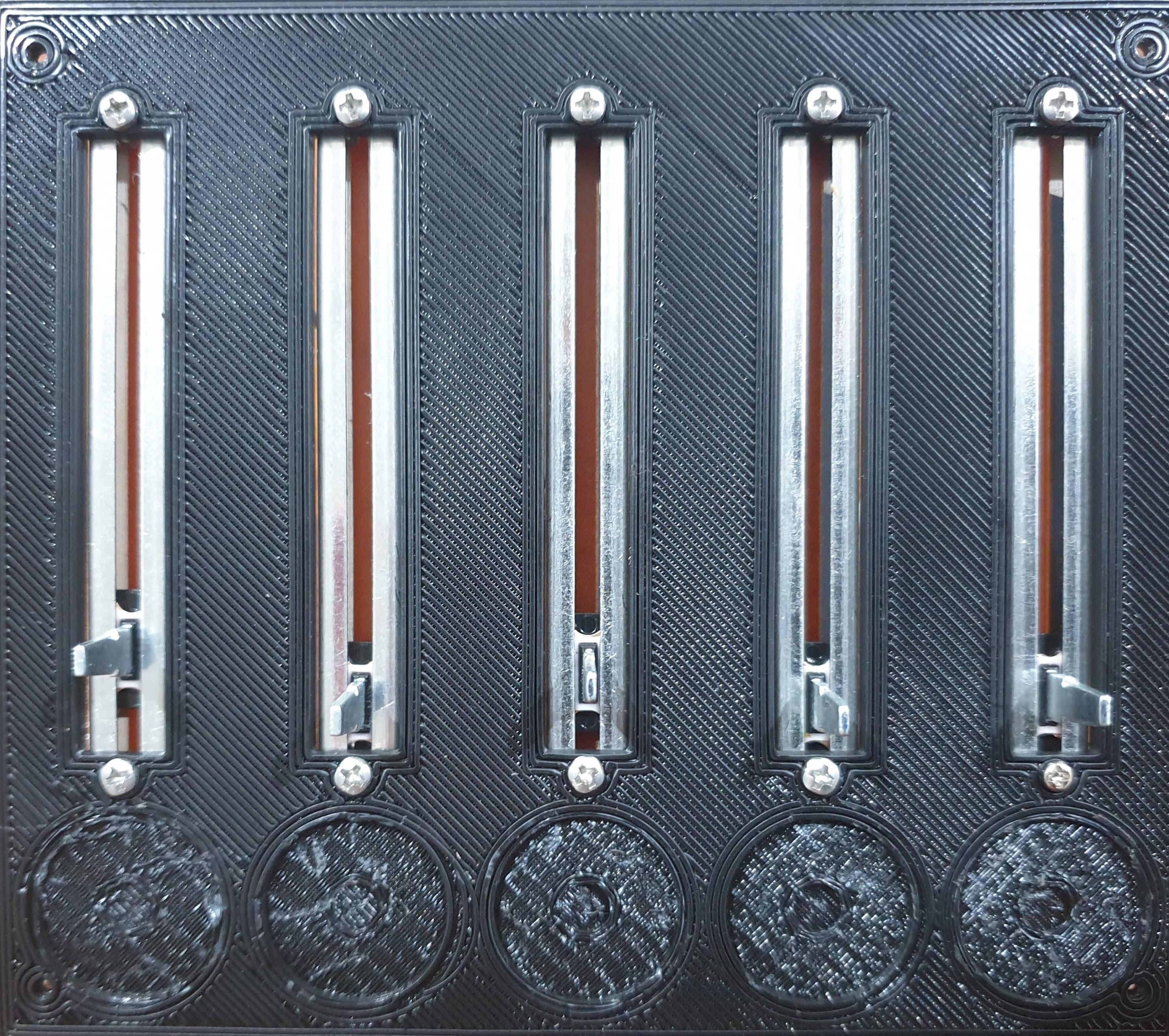
Using M2 screws, mount the sliders to the faceplate in their slots. One side of the potentiometer has two prongs, while one side has only 1. Ensure that all the potentiometers are orientated with the 2 pronged side at the top. The faceplate assembly should now look like this.
Wiring Time
Cut your wire so that you have:
- 8x 3cm-4cm lengths
- 7x ~10cm lengths
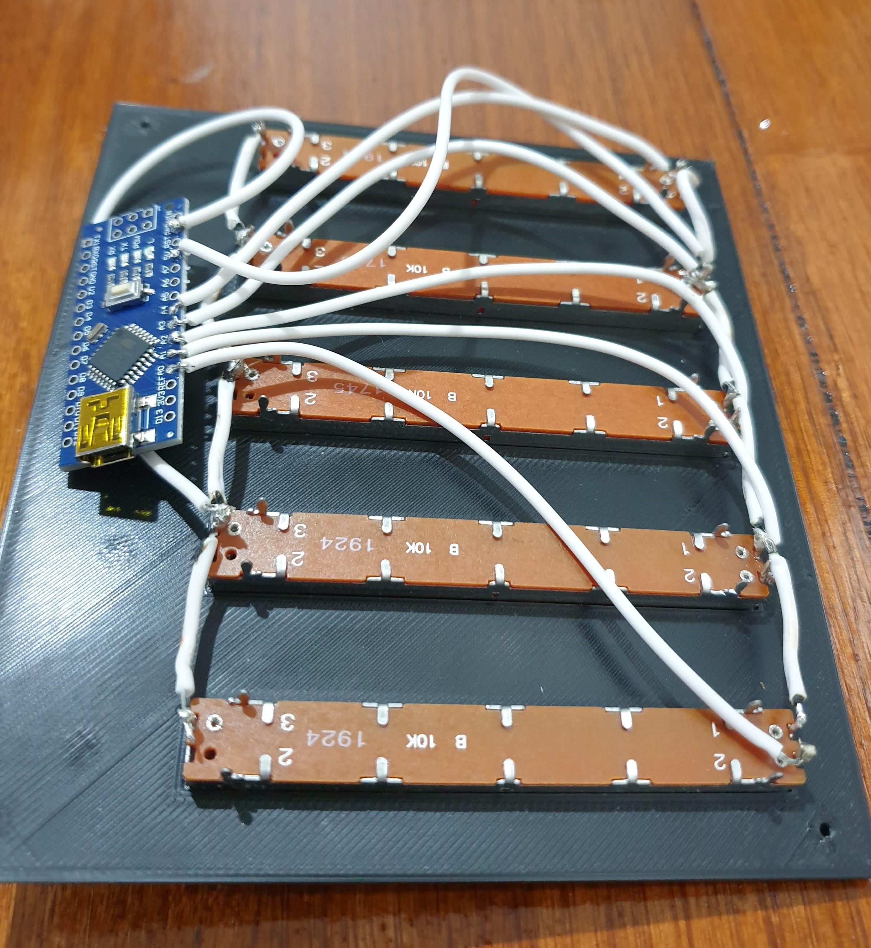
Use the shorter lengths to solder the top left pins of the potentiometers to each other. Do the same for the bottom pin, attaching each one to the next to form a line. When done you should have two straight lines wire attaching the potentiometers, these are the power lines.
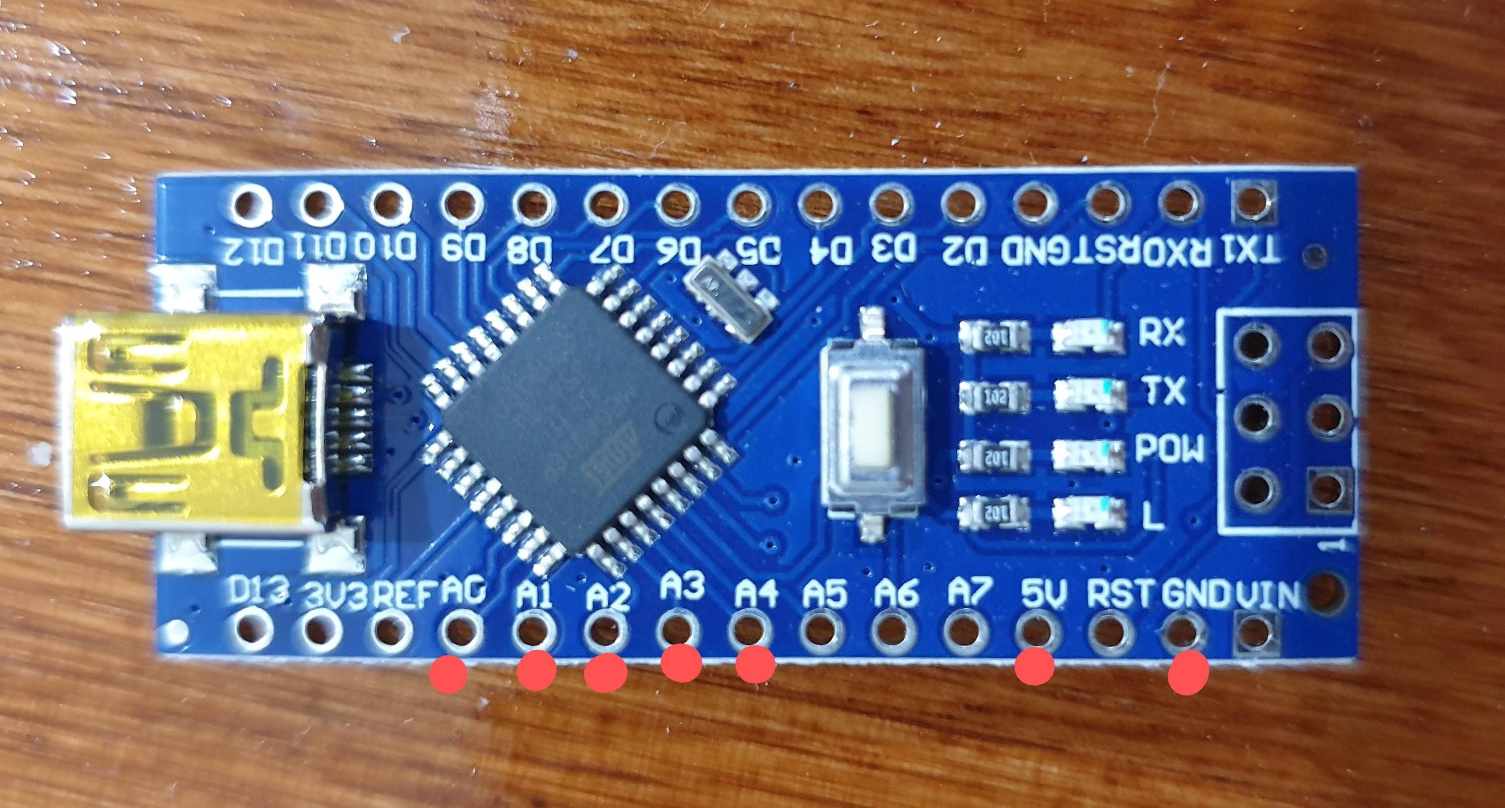
Referring to the photo for assistance, attach the 7 longer wires to the A0-A4 pins on the arduino as well as the 5V and GND pins.
Finally, attach the other end of the A0-A4 wires to the slider's top right pin,being careful not to bridge any connections to the top left pin, as they are very close to each other. A0 corresponds to the far right slider when viewed from the back (refer to notes on wired up picture for clarification). Attach the 5V wire to any one of the top left pins and the GND to any one of the bottom pins. The final result should look like this.
Assemble the Main Body
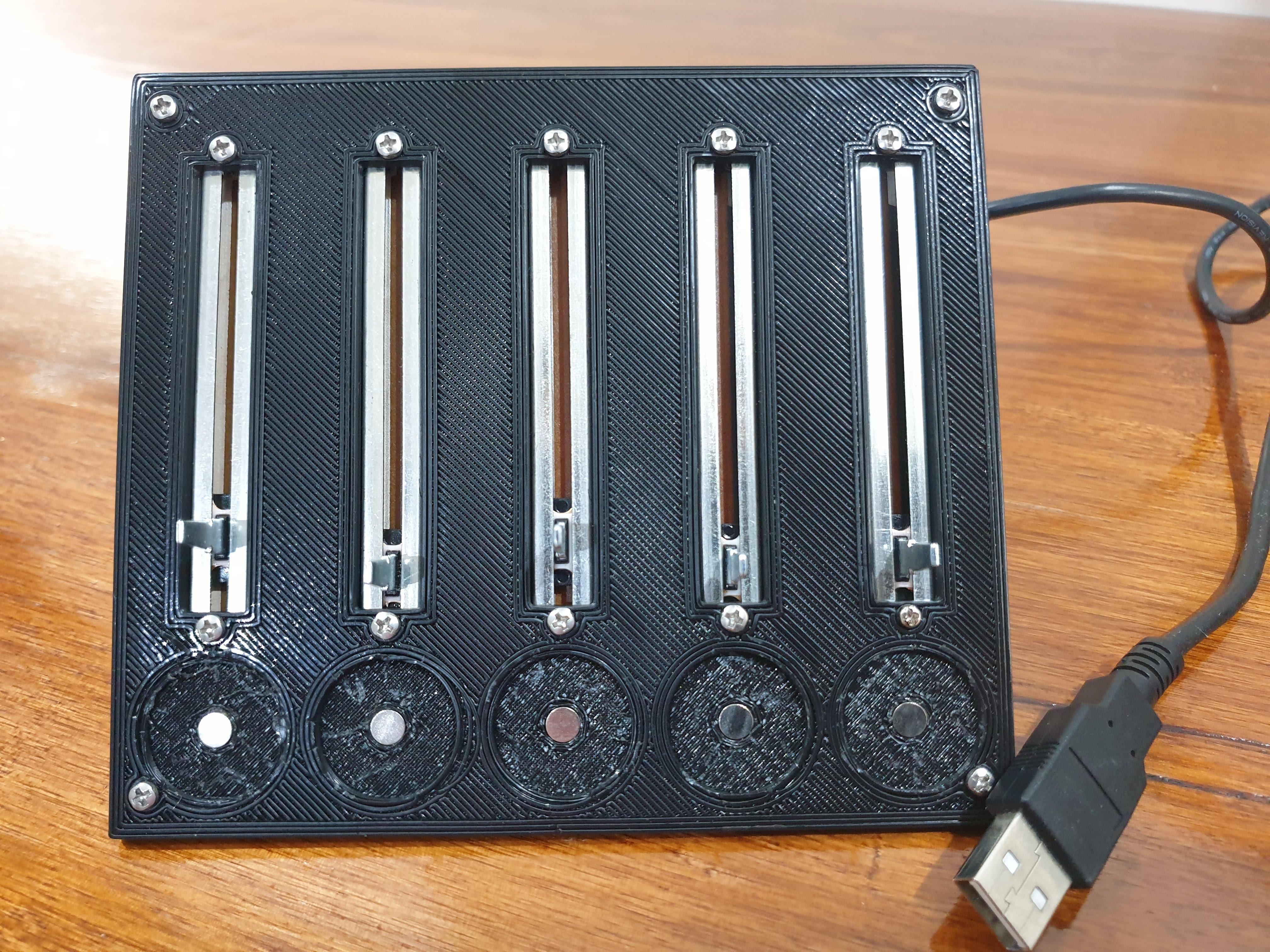
Get your mini USB cable, 3D printed main body and faceplate assembly along with 4 of the M2 screws.
Insert the micro B end of the usb cable through the hole in the body and insert it into the arduino. Then line the faceplate assembly up with the main body using the holes in both, ensure the arduino doesn't get crushed by folding it sideways as you do this. Use the 4 screws to tightly secure the faceplate to the body.
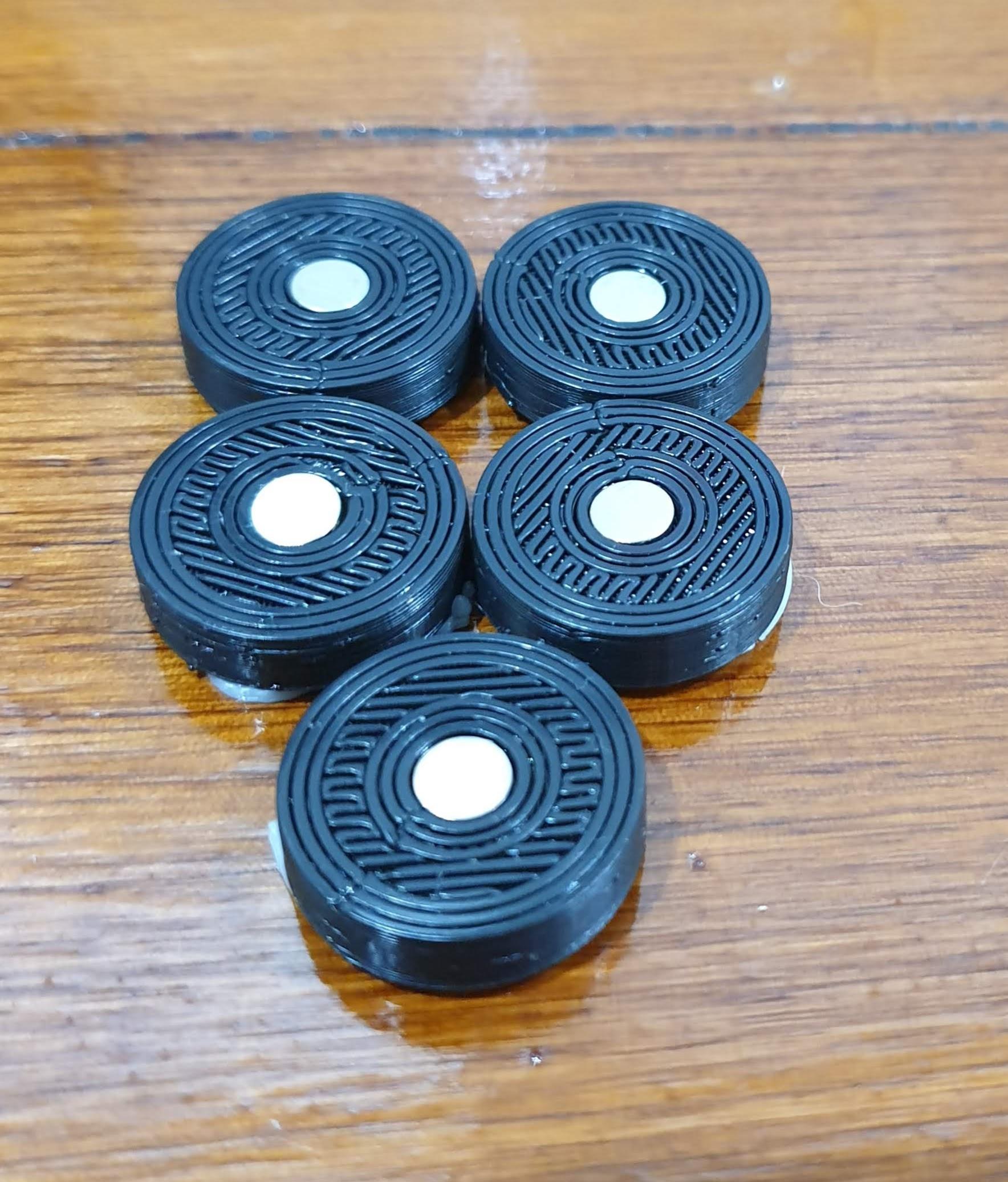
Also take this time to super glue magnets in the small holes at the bottom of the faceplate and the bottom of the badges. Ensure that all the magnets have one orientation in the faceplate and the other in the badges to ensure they will attract.
Attach the Sleeve
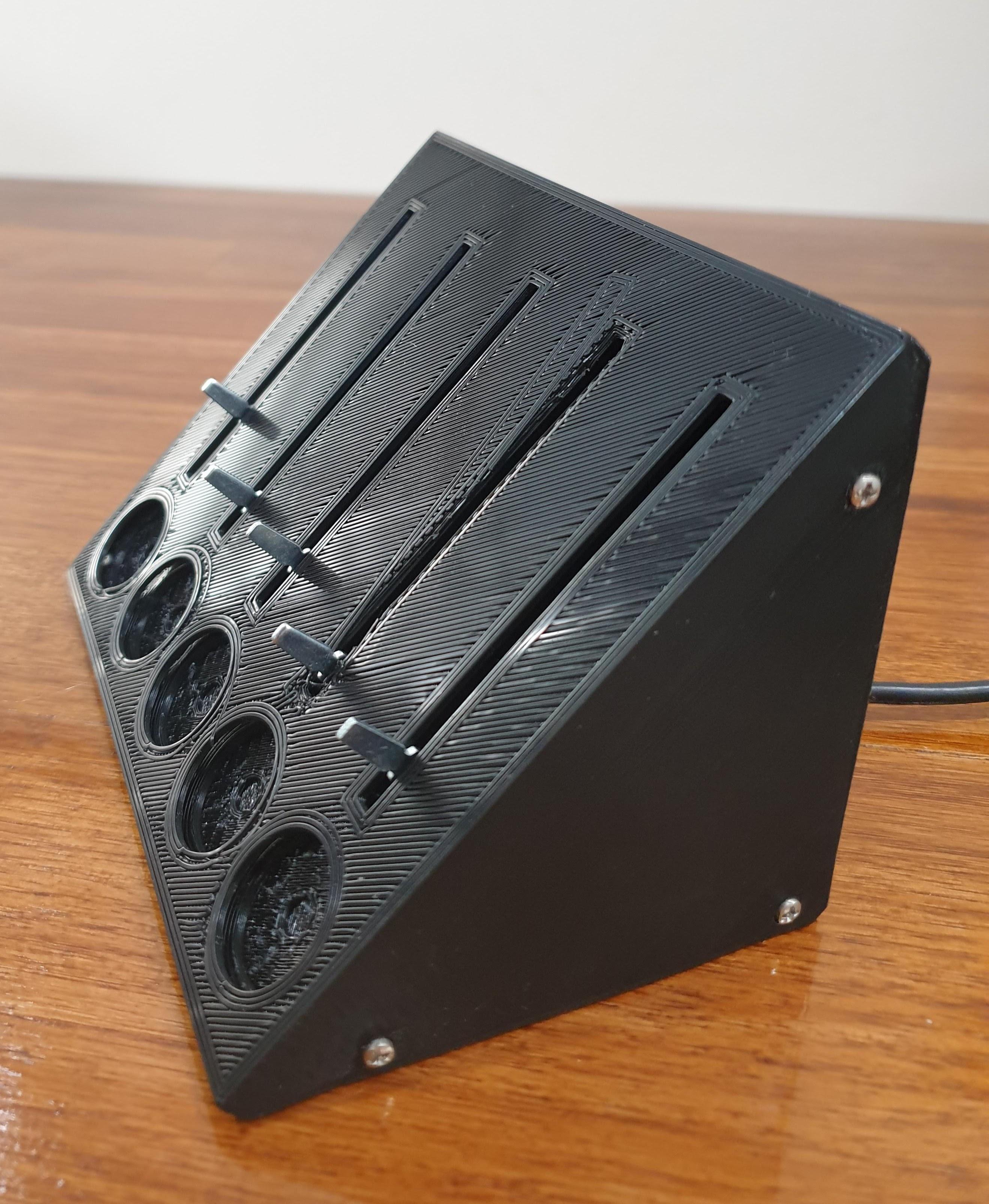
Slip the sleeve over the whole assembly so that the holes in the side of the body line up with the holes in the sleeve. Use 6 of the M2 screws to attach the sleeve firmly.
Finishing Touches
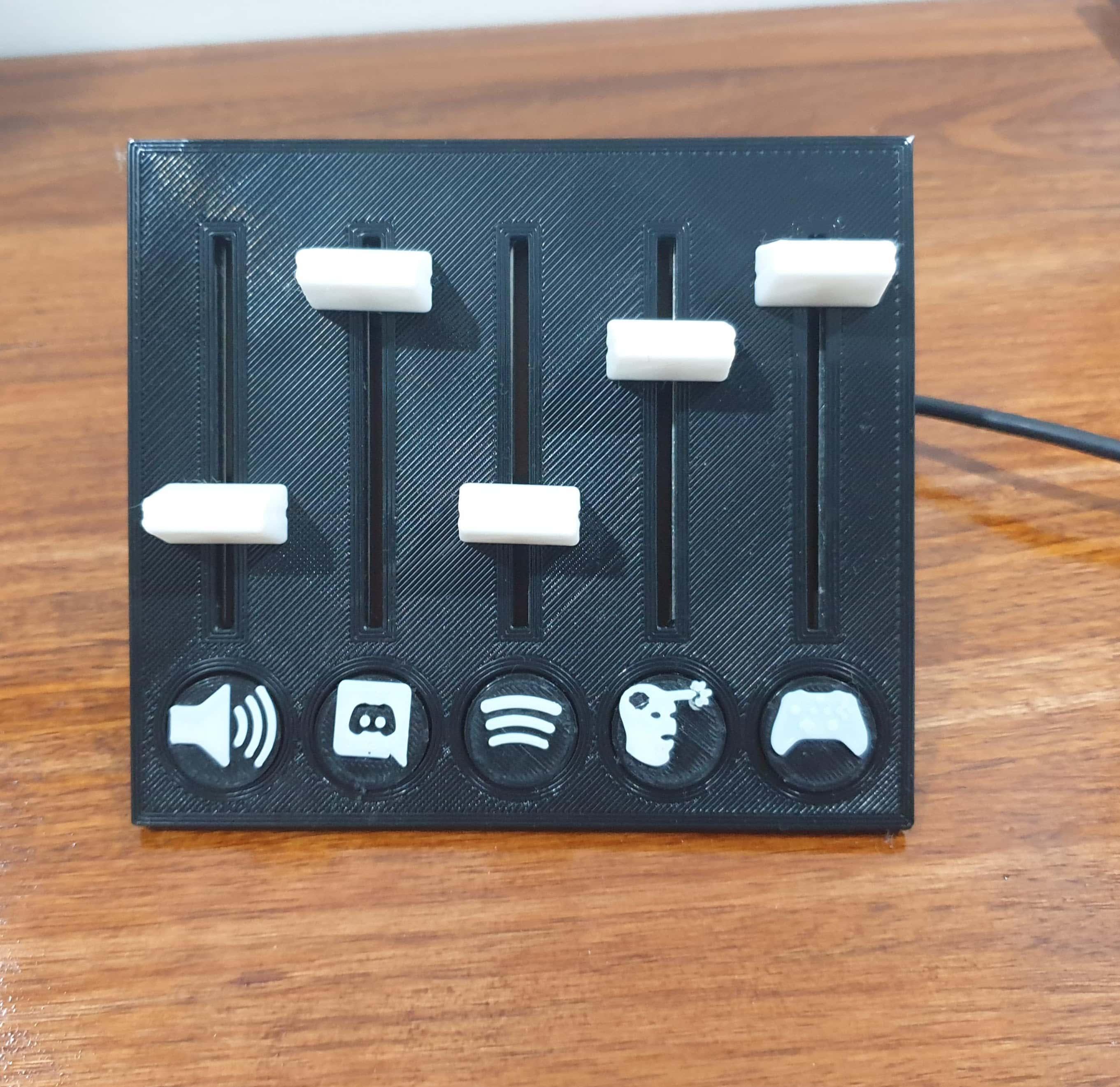
Carefully push and wiggle the knobs onto each of the sliders now. It's a little tricky but a tight fit is essential to use so take your time. One all 5 are done attach the badges in whatever order you wish to have your programs in.
That is now the mechanical assembly done and it's onto software.
All the Software
Head over to the Arduino site and download the latest IDE and get that installed
Plug in the Deej box and open the Arduino IDE
Flash your arduino with this sketch
Now to check that everything is working correctly, open up the serial monitor and you should see 5 values between 0 and 1023 depending on the sliders' positions. If you do not see this disassemble to get access to the wiring and ensure everything is as it should be. Ensure all wires make good contact and are not loose/falling off.
If all is well then you can move onto the deej program.
Head over the the Deej releases page and download deej.exe and config.yaml and put them in the same folder on your PC. I put them in a folder called Deej.
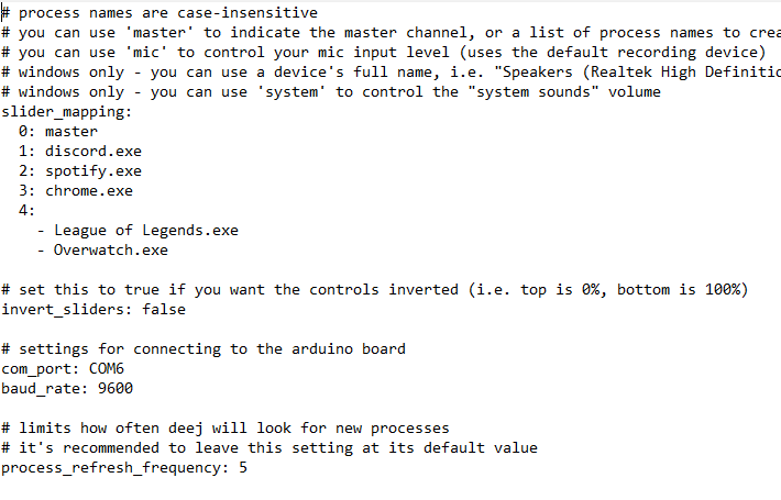
Open the config.yaml file and assign each slider to one or more programs as seen here. Remember that 0 is the far left slider and 4 is the far right. Also assign the correct COM slot the arduino is on. This can be found in Device Manager on Windows, under Ports (COM&LPT) while it is plugged in.
Success & More Info
