Decorative Iris Box Guide
by Brien Allison in Workshop > 3D Printing
6402 Views, 84 Favorites, 0 Comments
Decorative Iris Box Guide
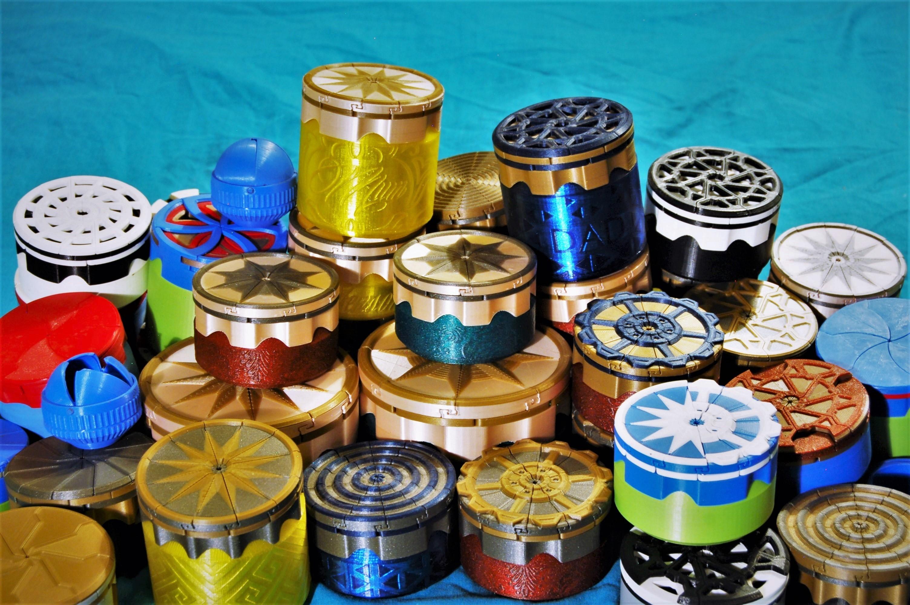
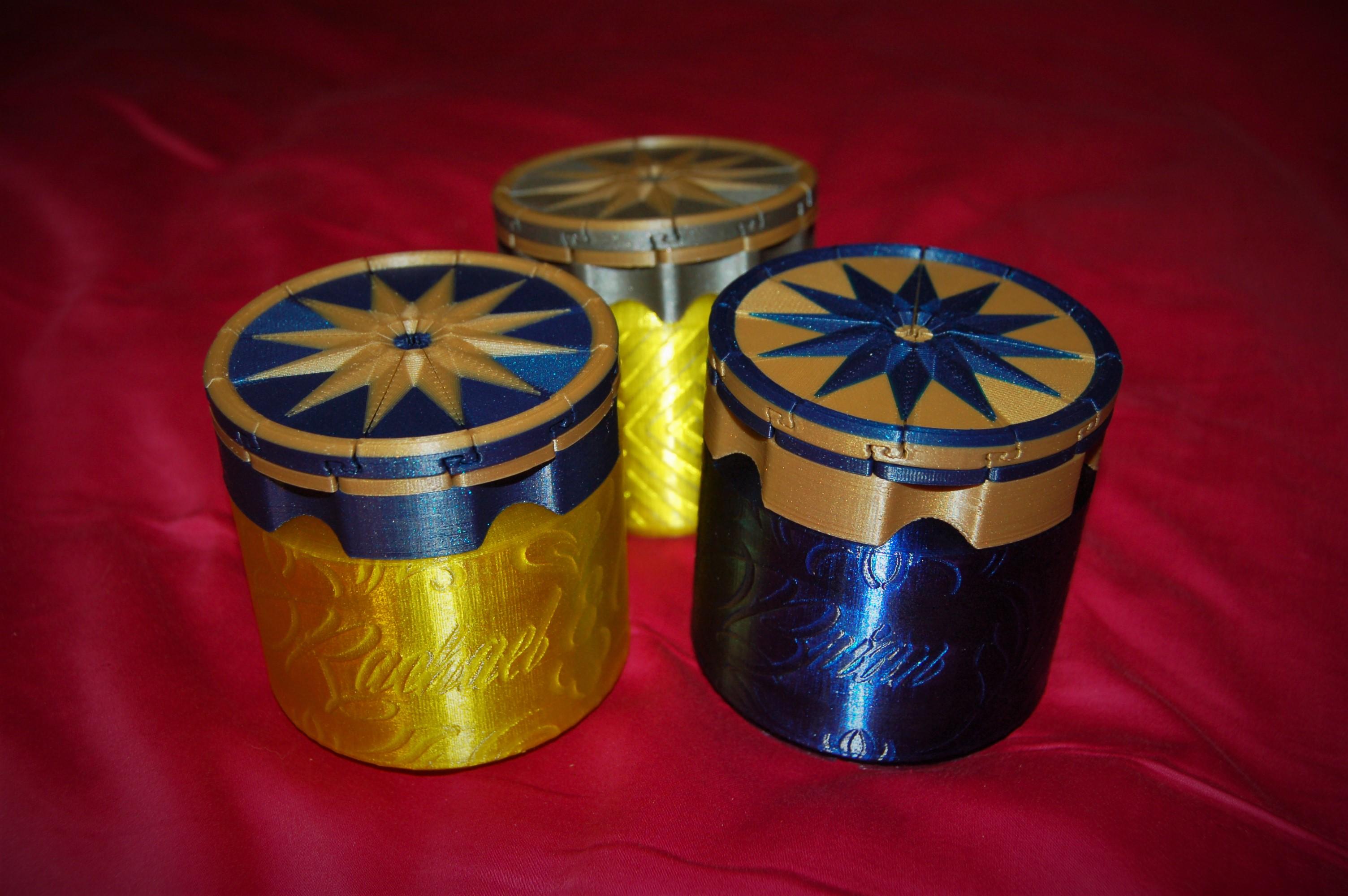
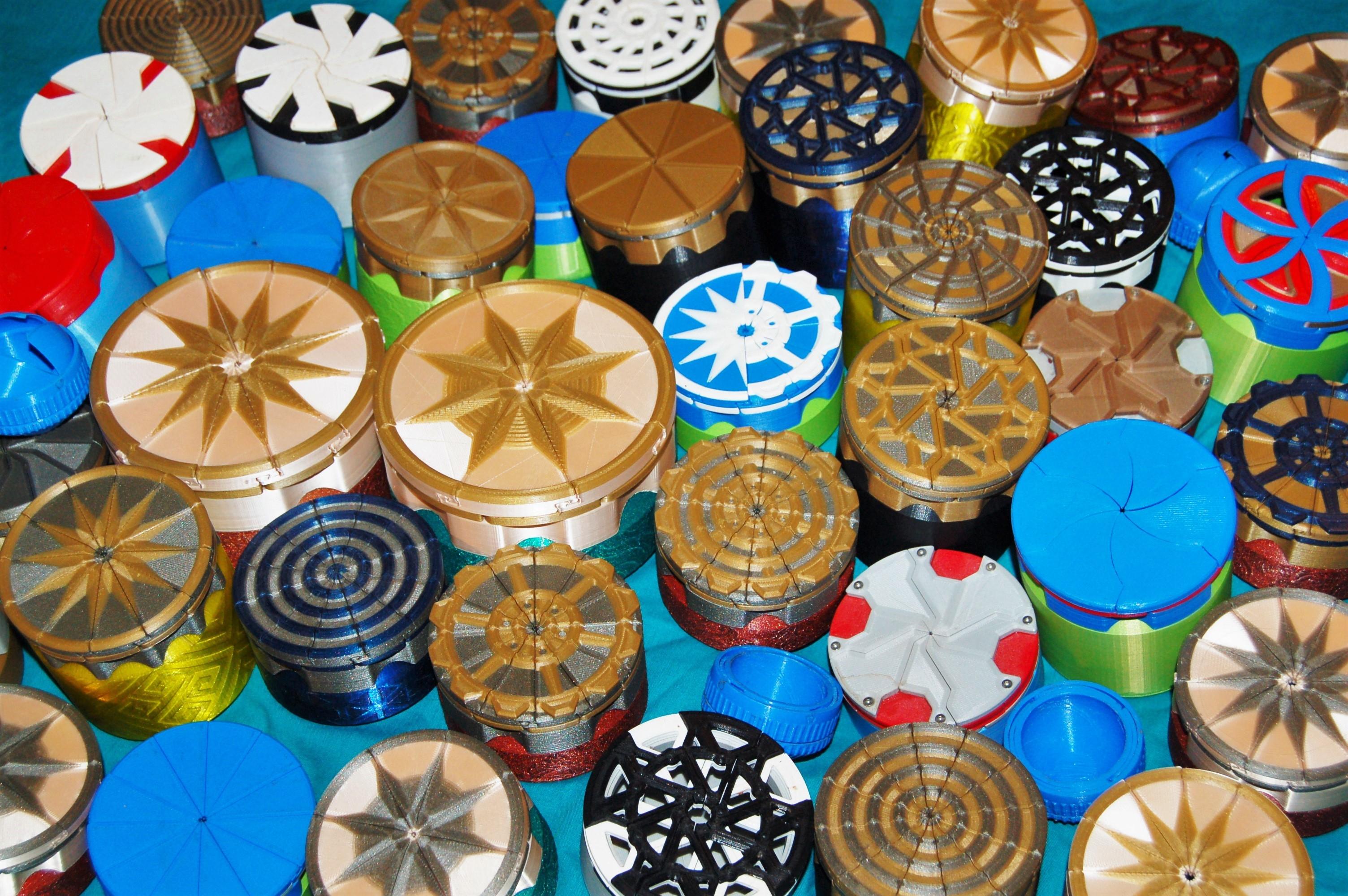
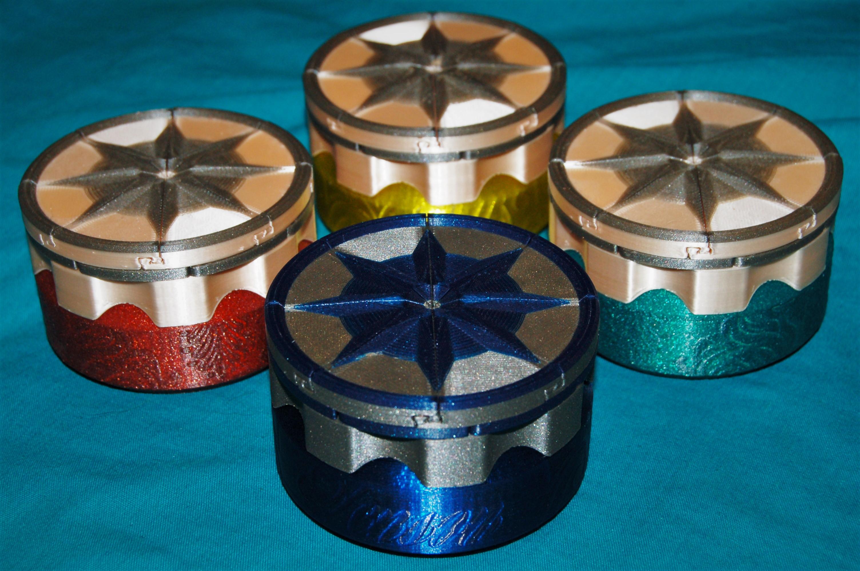
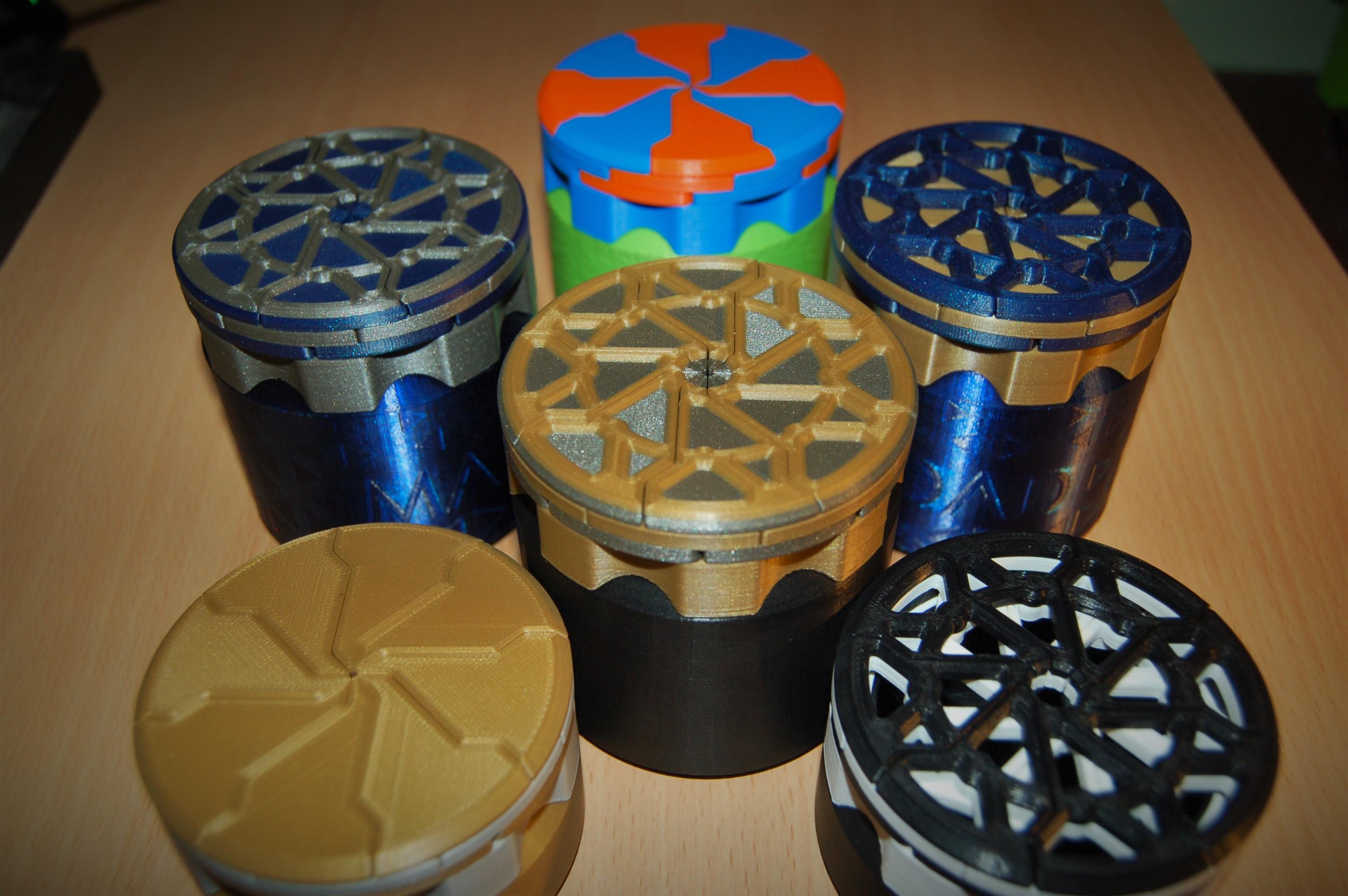
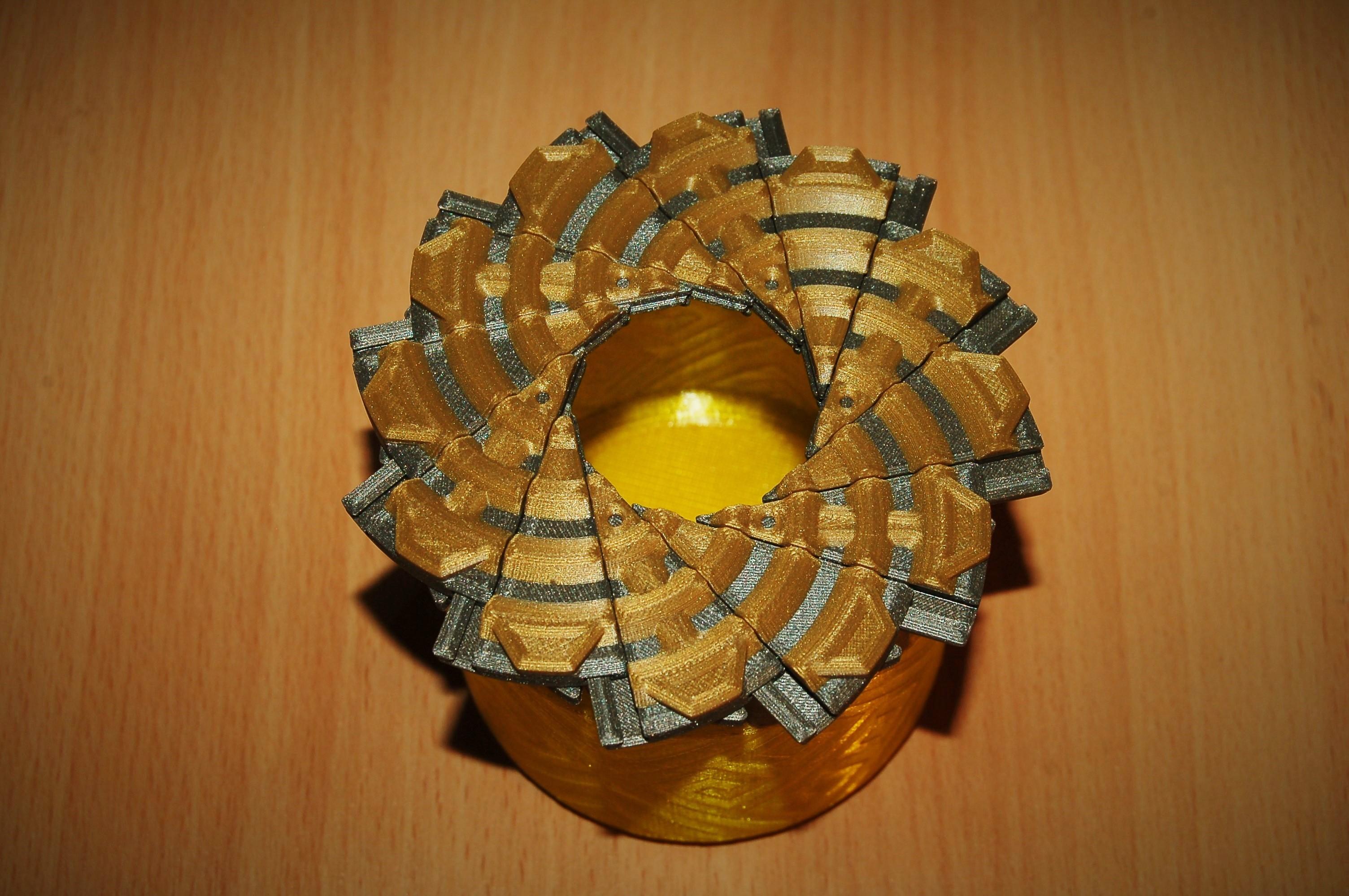
I like iris boxes. So much so that I published 14 designs and have made countless of them as gifts; a selection is shown in the images in this instructable. Here I will go through the tricks and tips I have learned to print my designs to a high quality with decorative multi colour patterns and customised velocity painted containers.
There are too many designs to cover each in detail (there is more info on the specific design pages) but this guide will focus on the '12 Leaf Aperture Iris Box' since that is the most difficult to print. The general details of this guide can then be applied to all the other designs.
Before I get into the details of making the boxes, I will give an overview of all the box designs and the three families of mechanisms:
Supplies
- 3D printer + filament colours of your choice. PLA is ideal for its ease of printing.
- M2x6 countersunk screws or larger for scaled models e.g. M3x8 at 150% scale (screws are not necessary for the earlier designs but I highly recommend the later designs since they are much higher quality).
Flower Iris Boxes
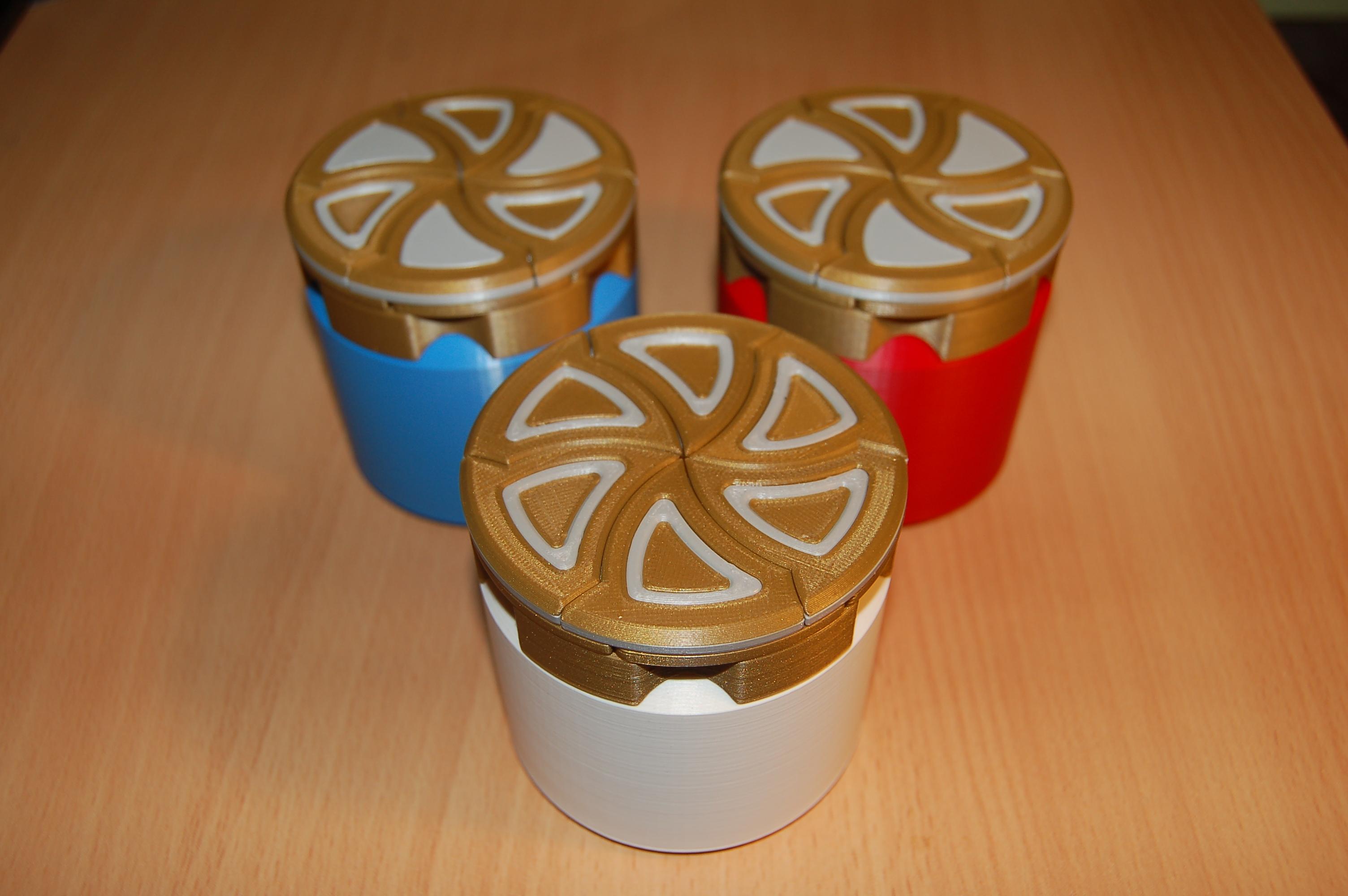
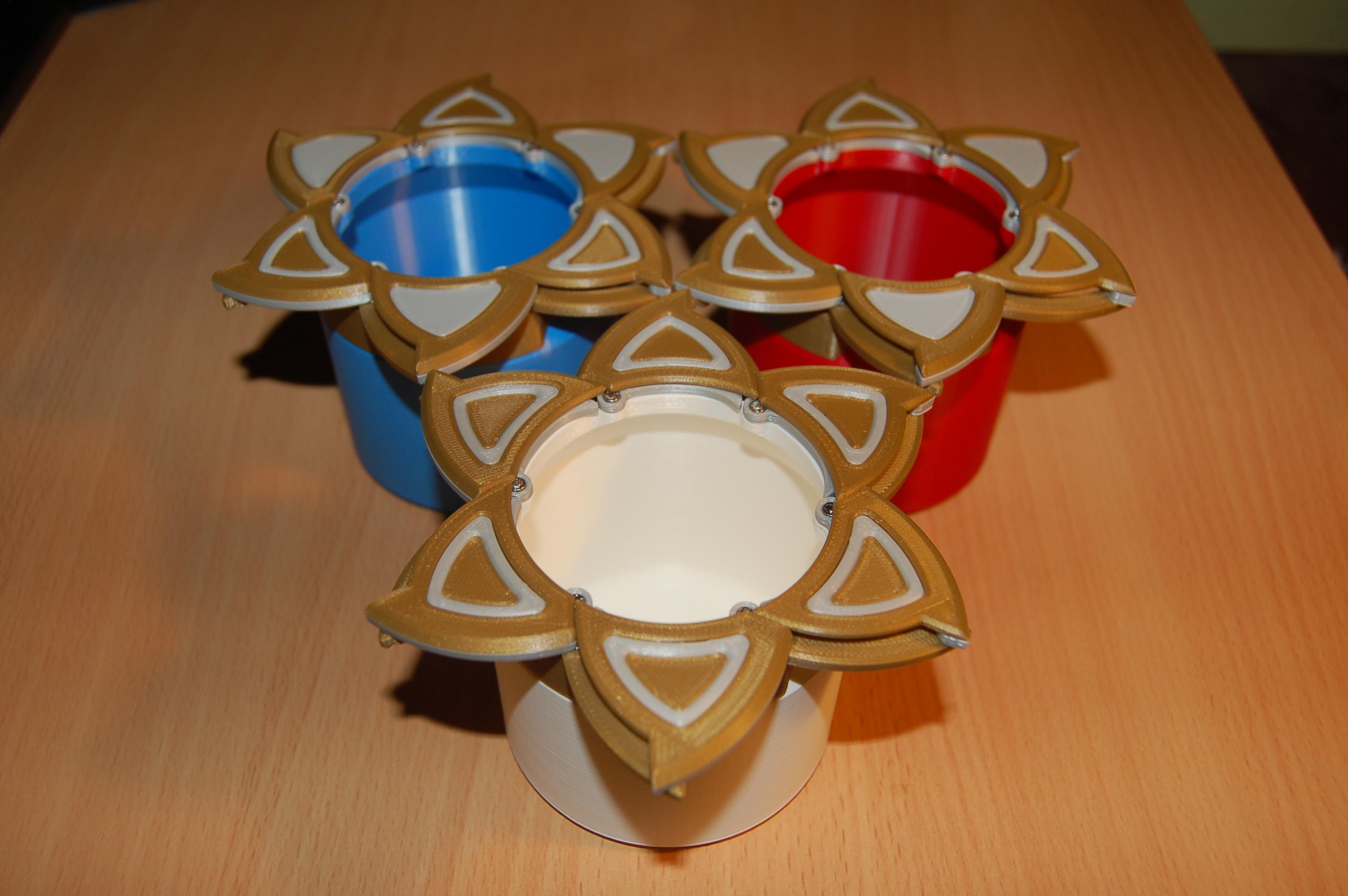
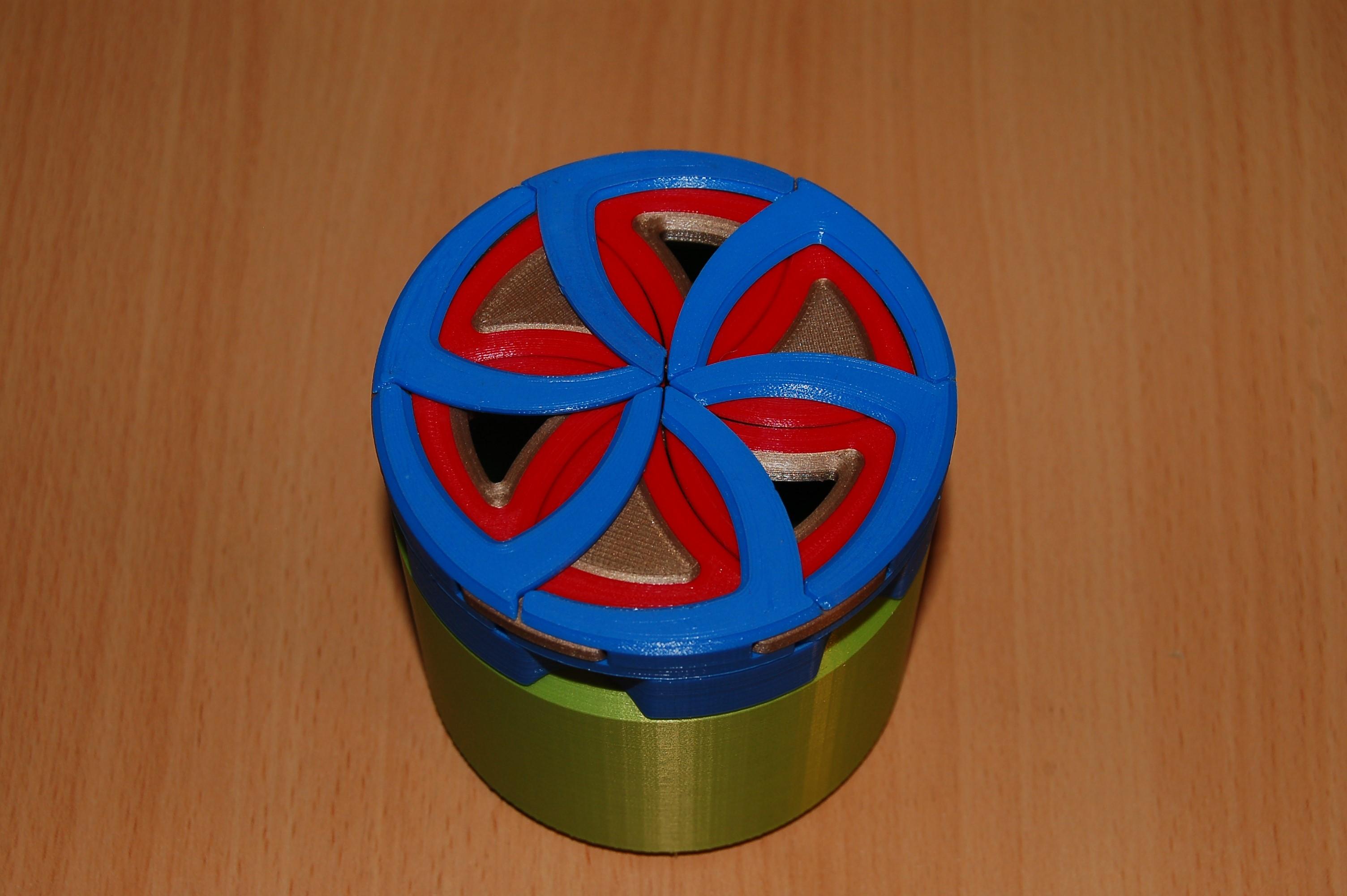
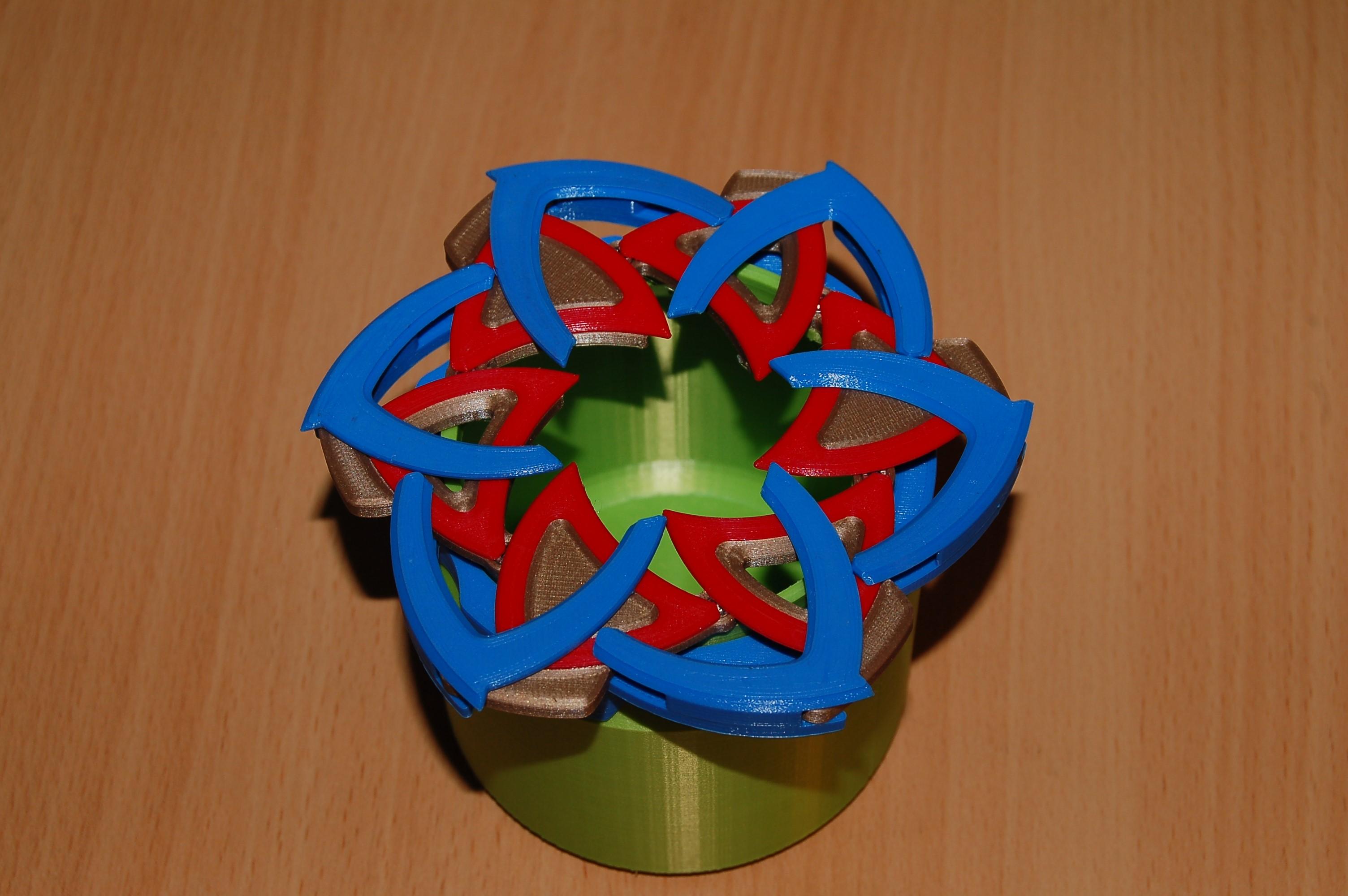
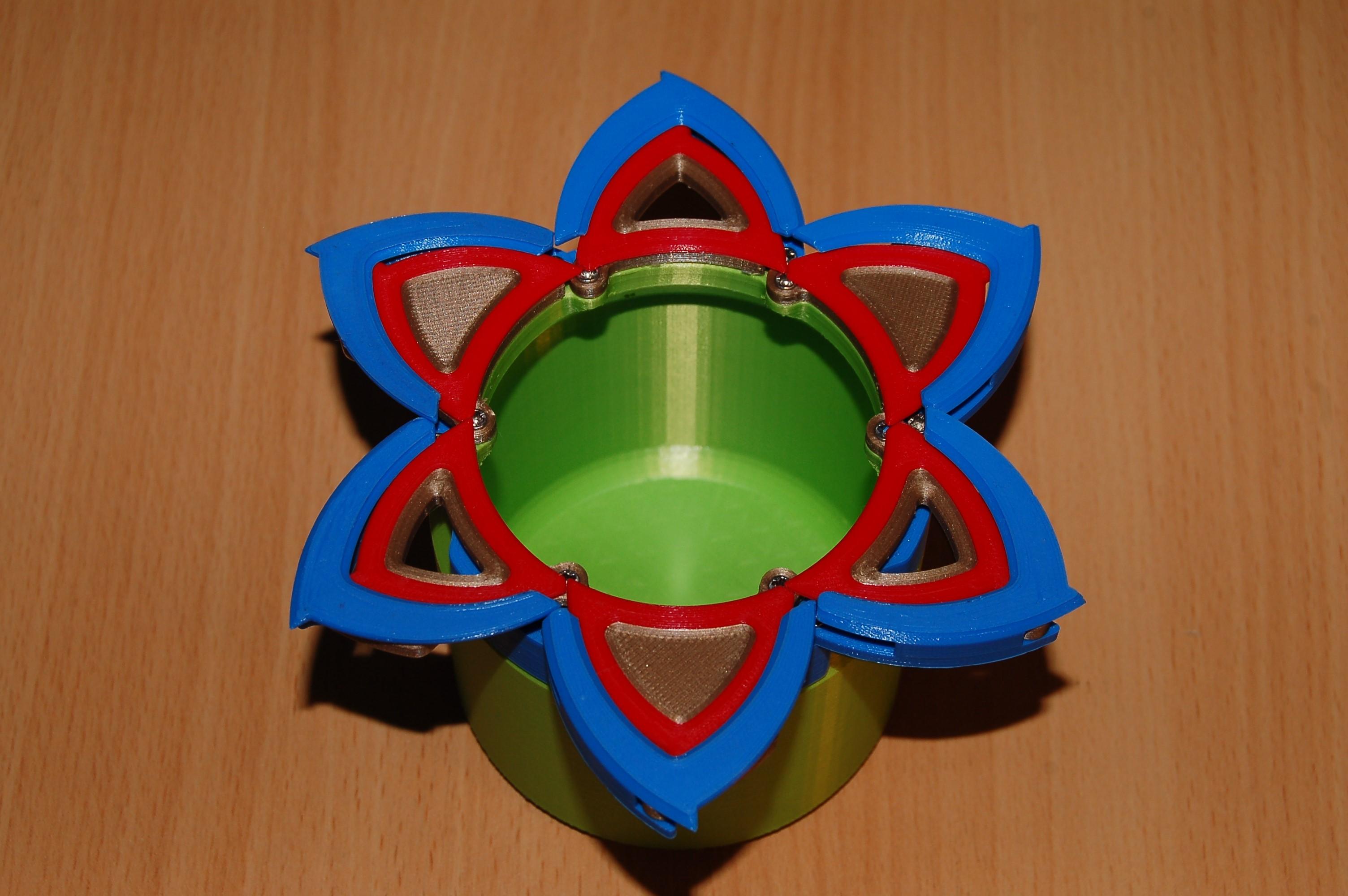
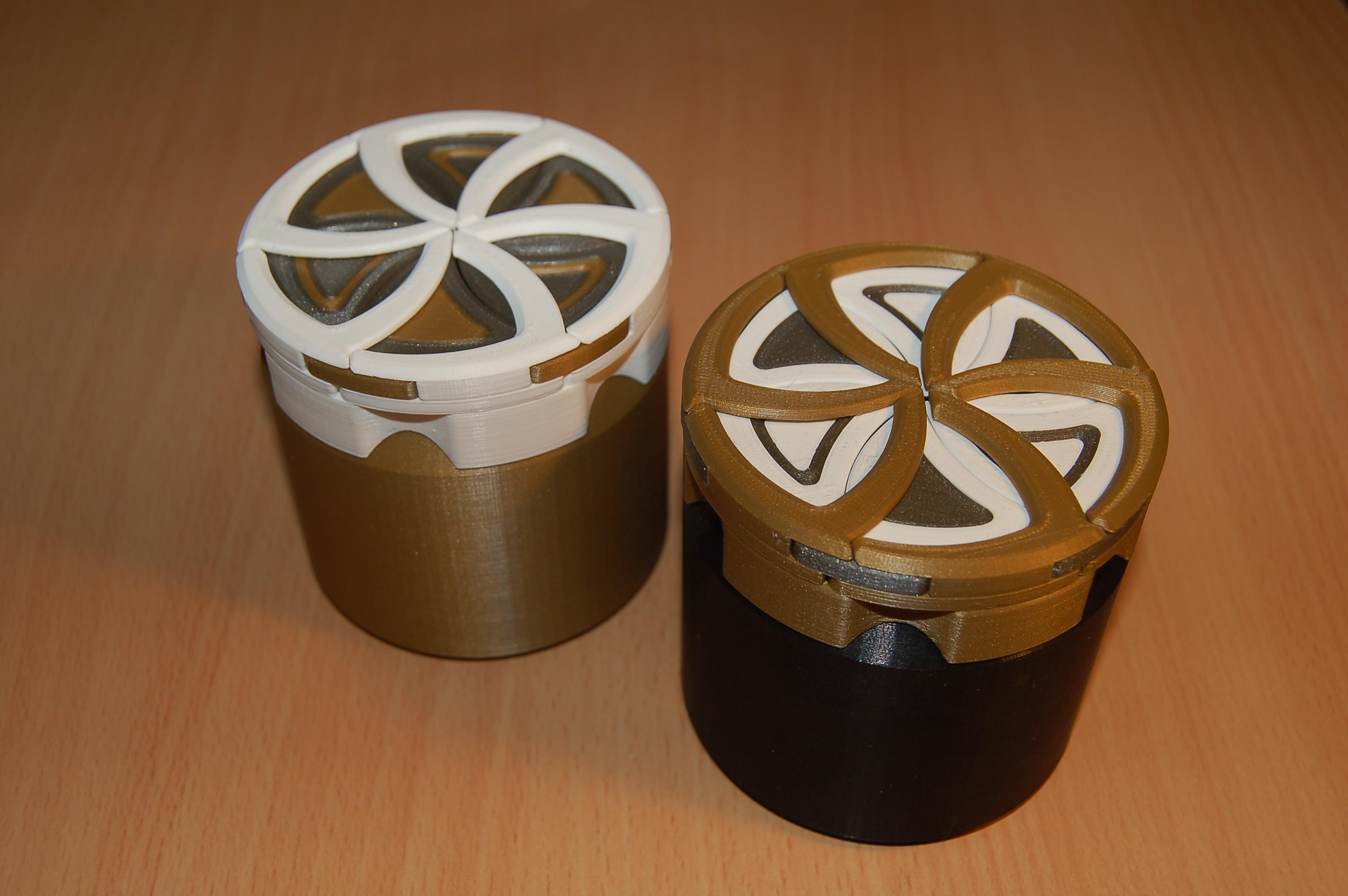
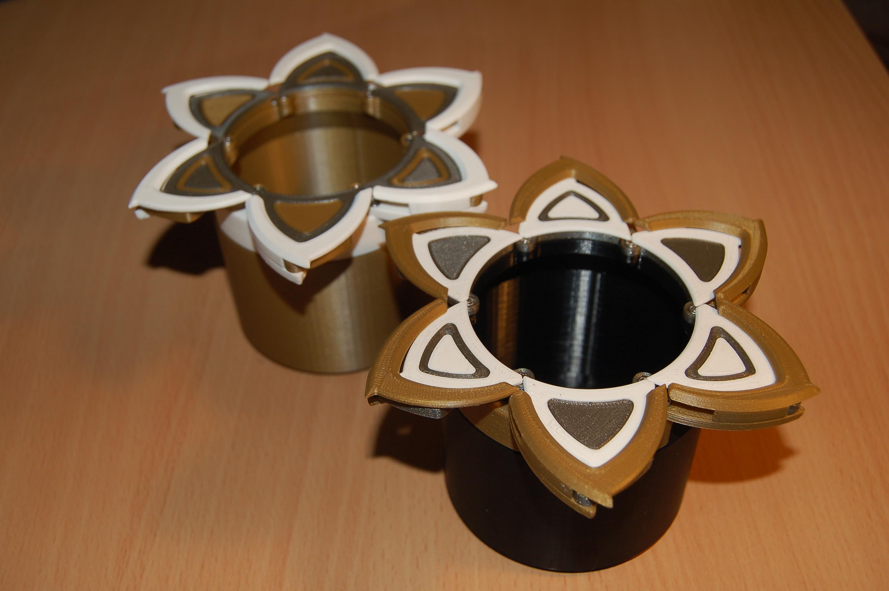
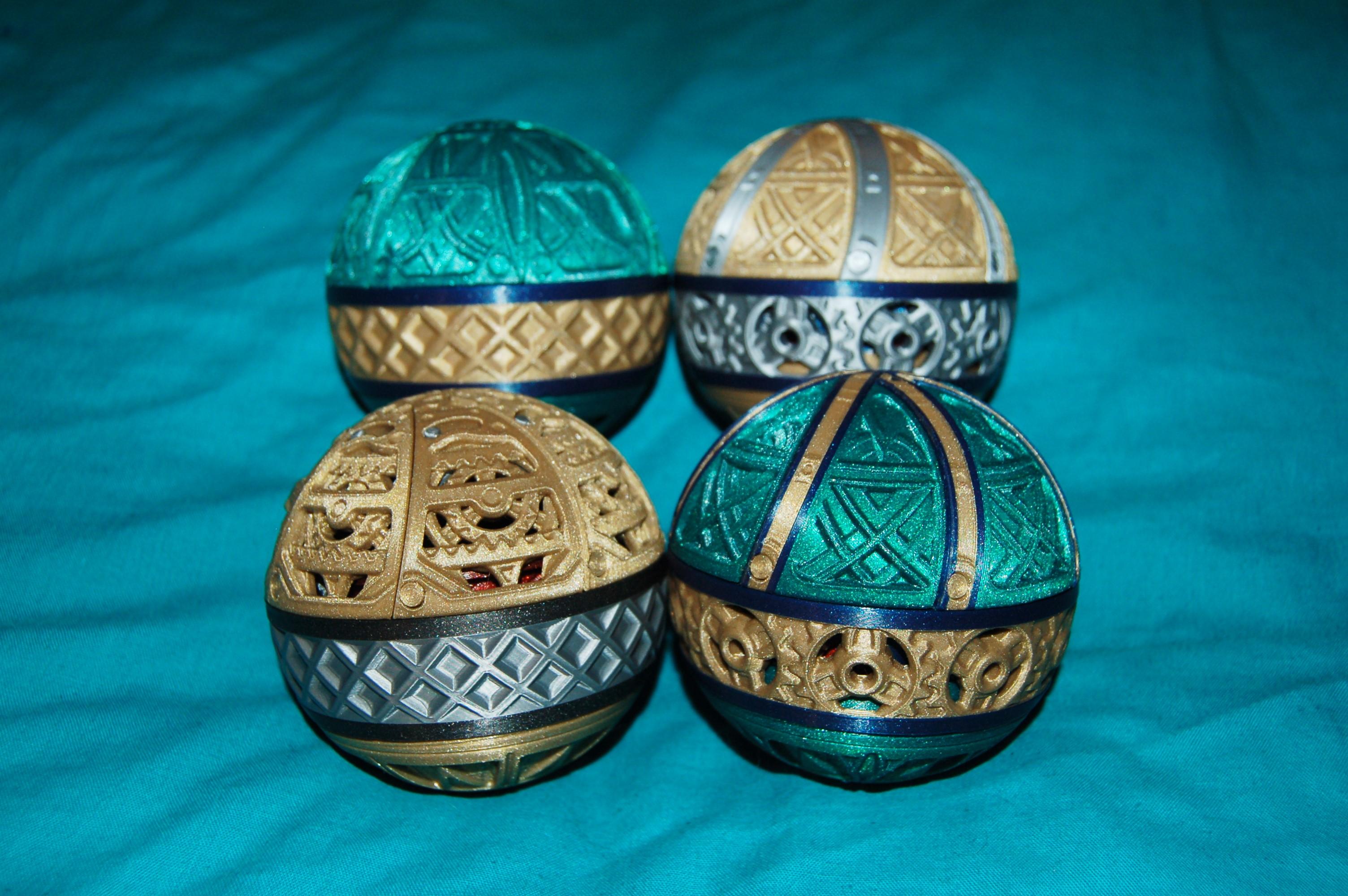
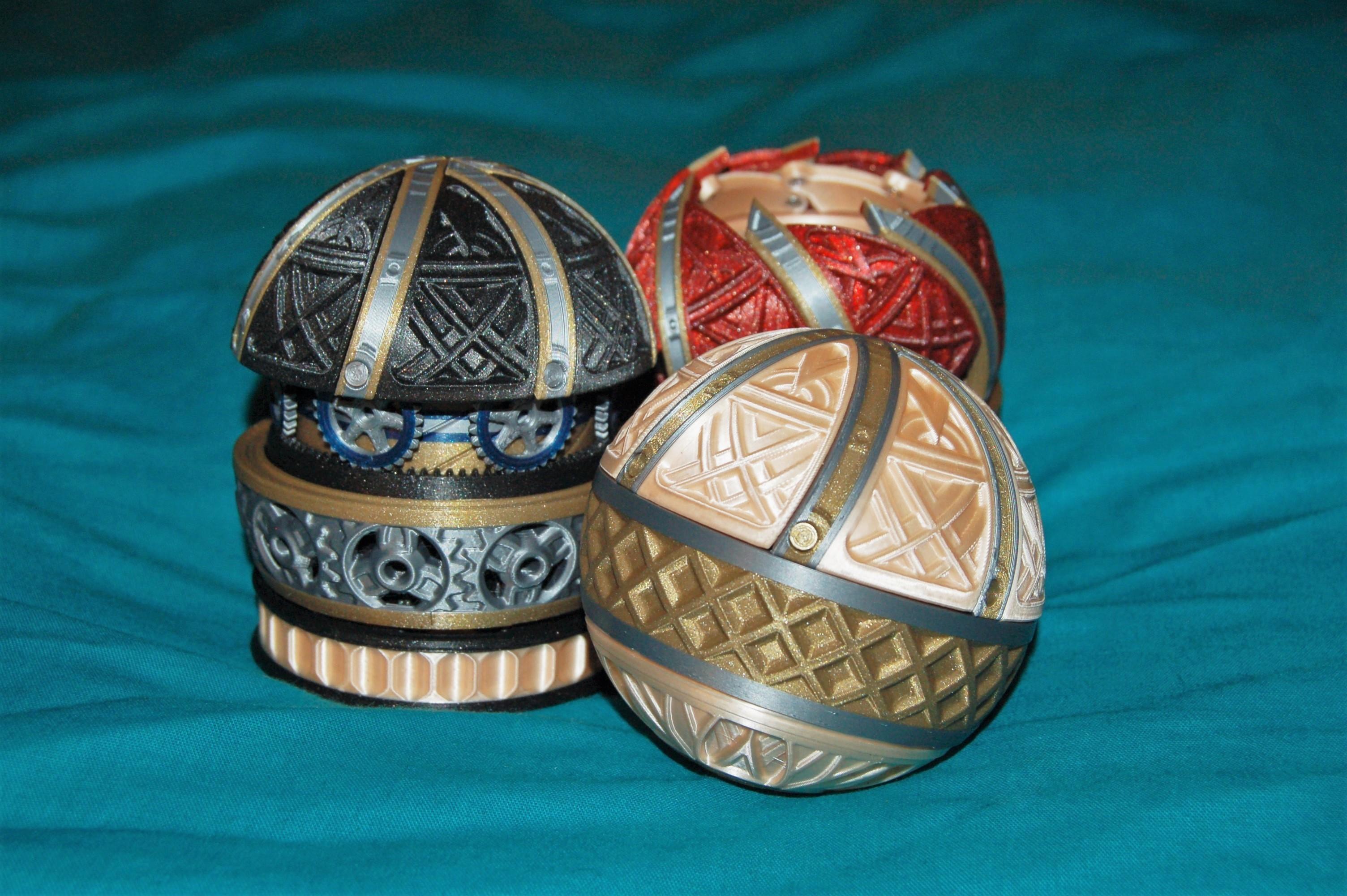
Similar to the common 5 petal iris box designs, these boxes have 6 petals and operate with a linkage based mechanism. You can see the box moving in this video and this make.
- Flower Iris Box. My first published design uses no screws and the parts simply clip together. A simple design although care has to be taken to use the correct layer heights for the mechanism to work.
- Flower Iris Box V2. An upgraded version of the flower iris box which uses screws to assemble and is generally much neater and more colourful. 18 screws required.
- Double Flower Iris Box. A more complex variation on the flower mechanism, which adds a second layer of petals attached to the links which open in the opposite direction to the base petals. 24 screws required.
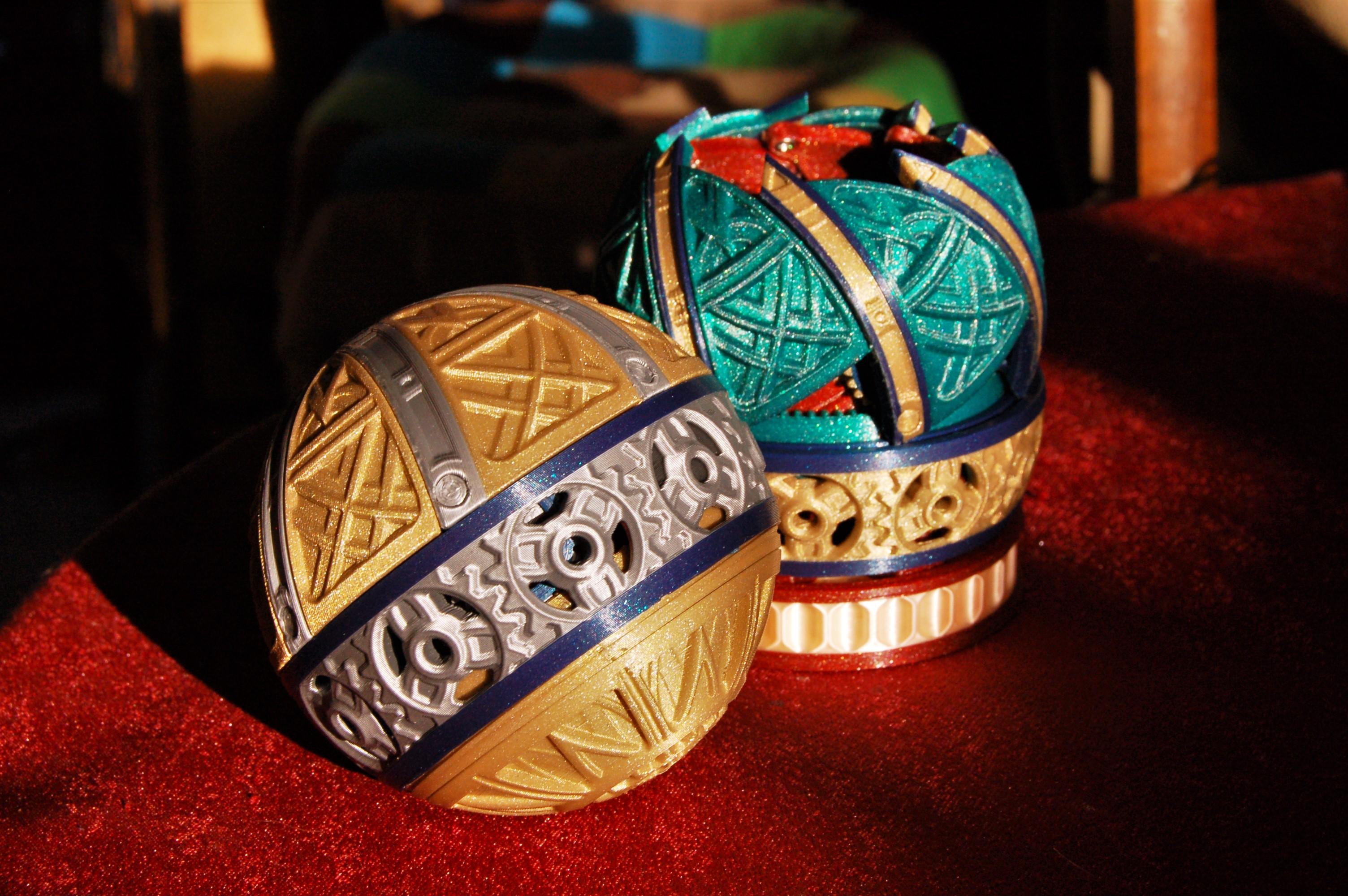
- Orb-box. A print in place iris box similar to the well known designs of Emmet and Lobo CNC. This is not so much a decorative iris box as a novel mechanical design to show off what 3D printing can do (and a 3D printing challenge to make), but it is included here for completeness.
- Orbox. My newest and most complex design, it is perfectly spherical when closed, with many decorative designs.
Octo/Dodeca Boxes
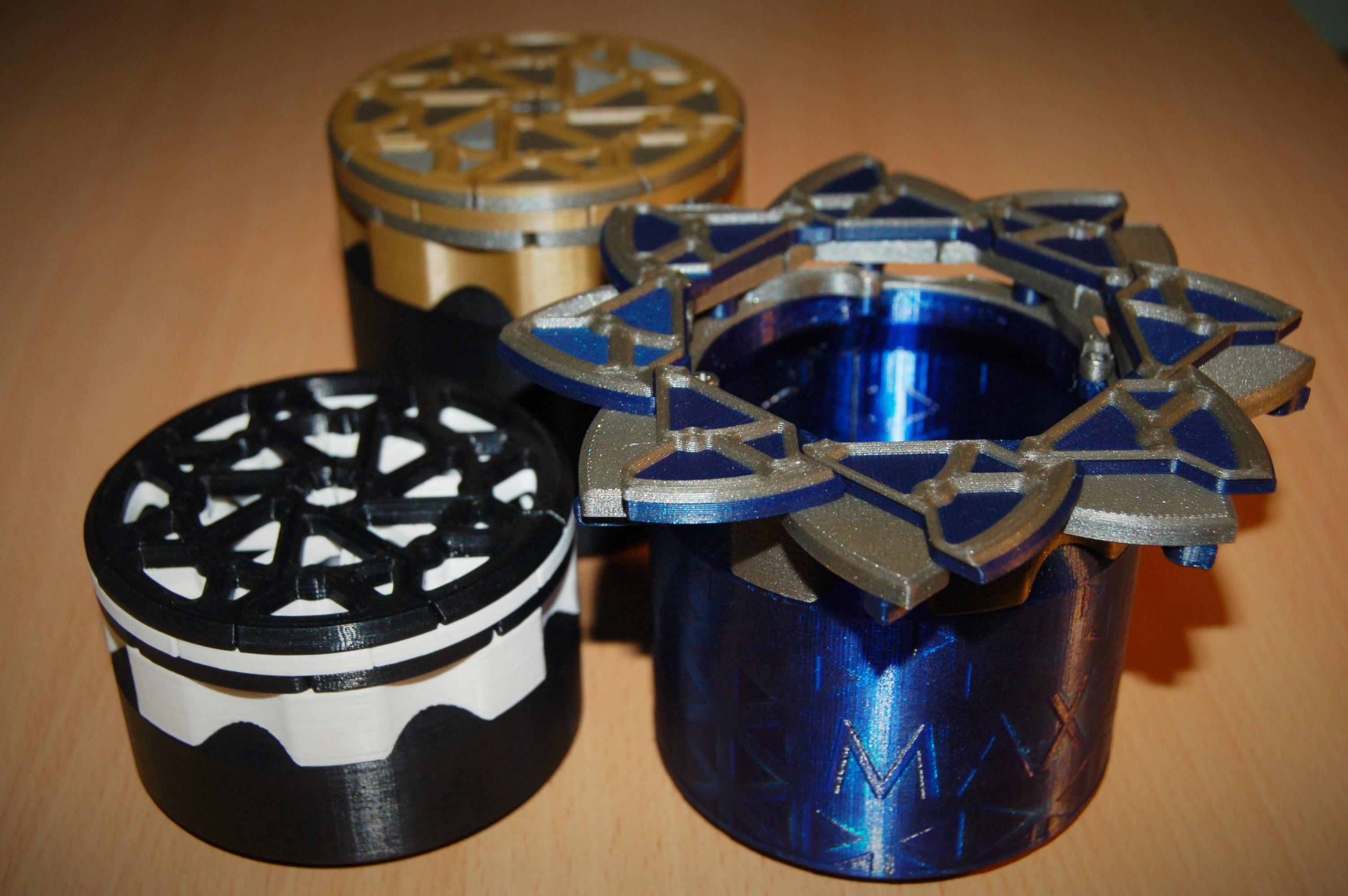
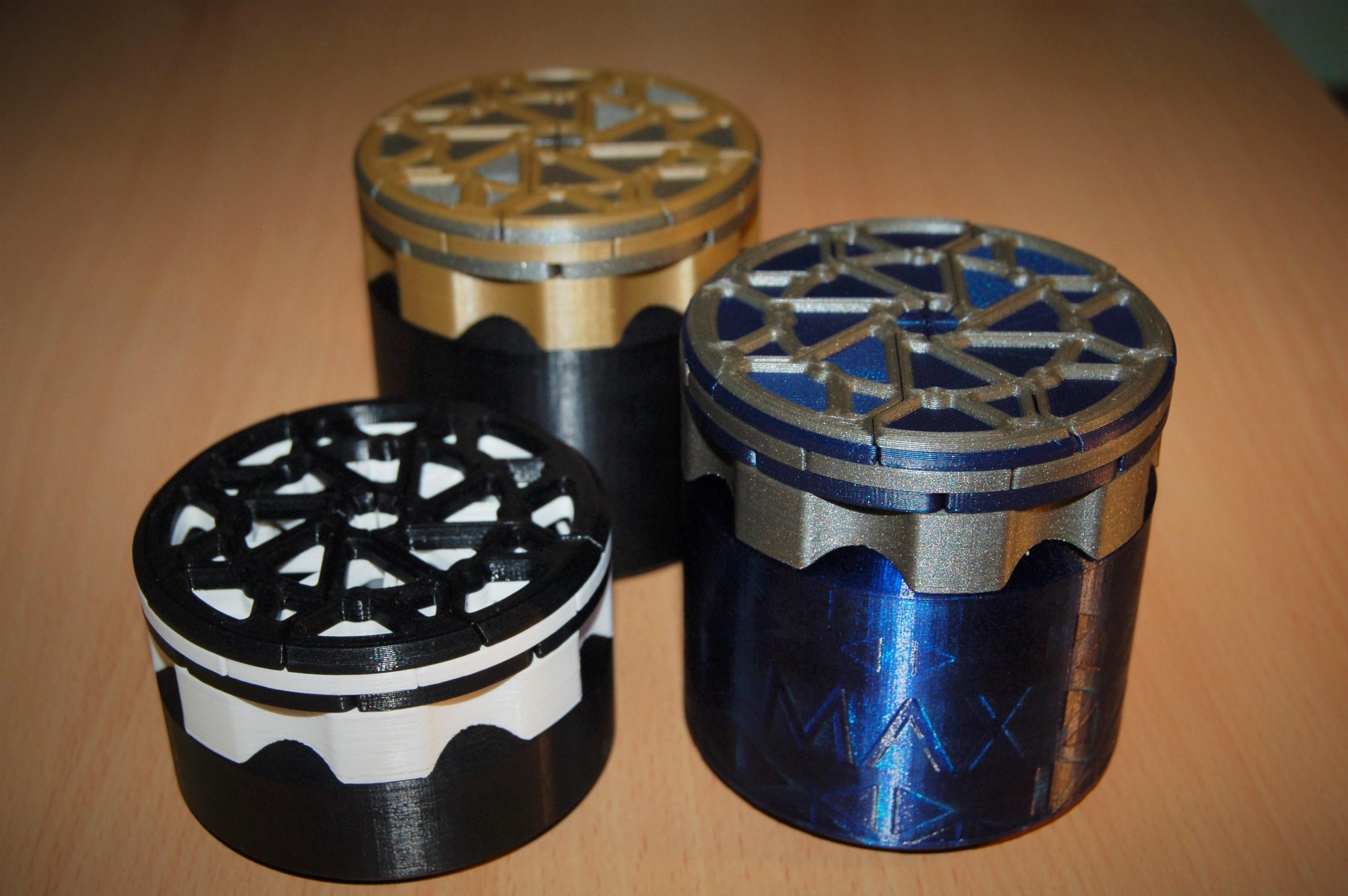
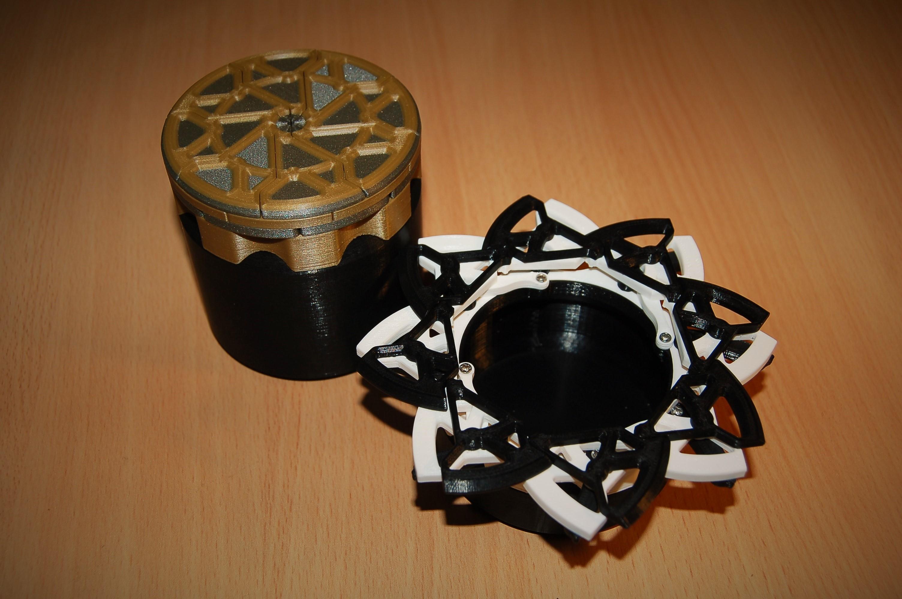
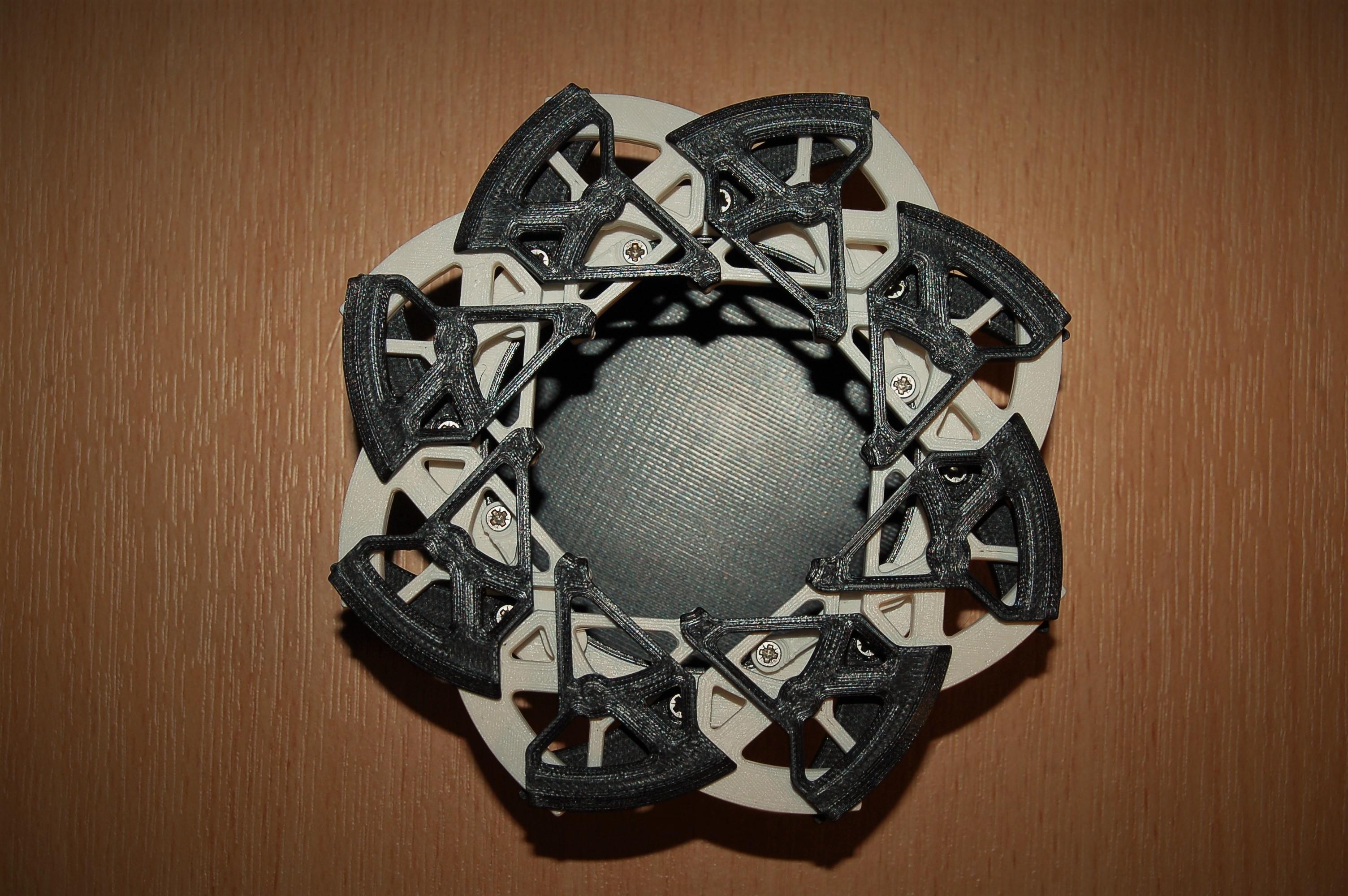
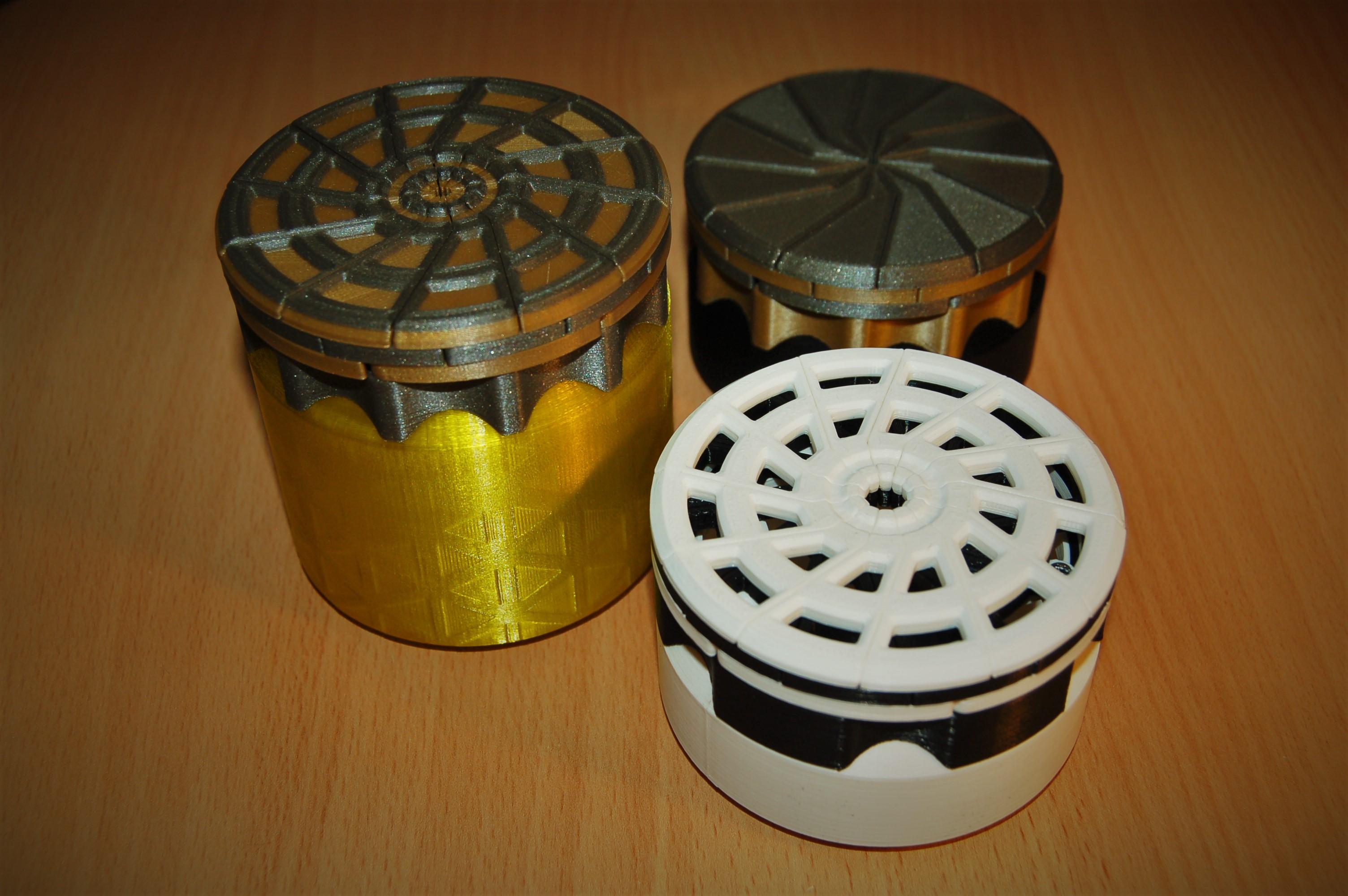
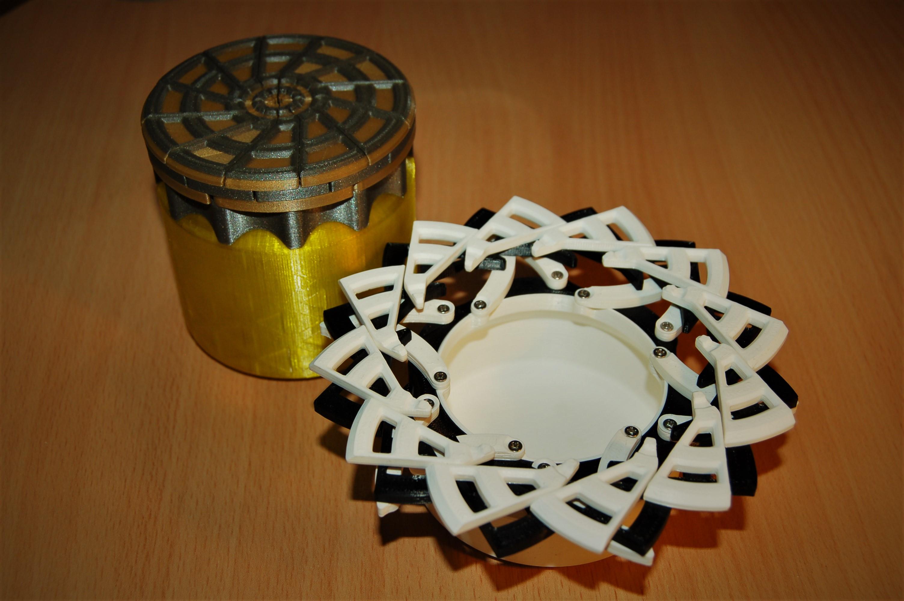
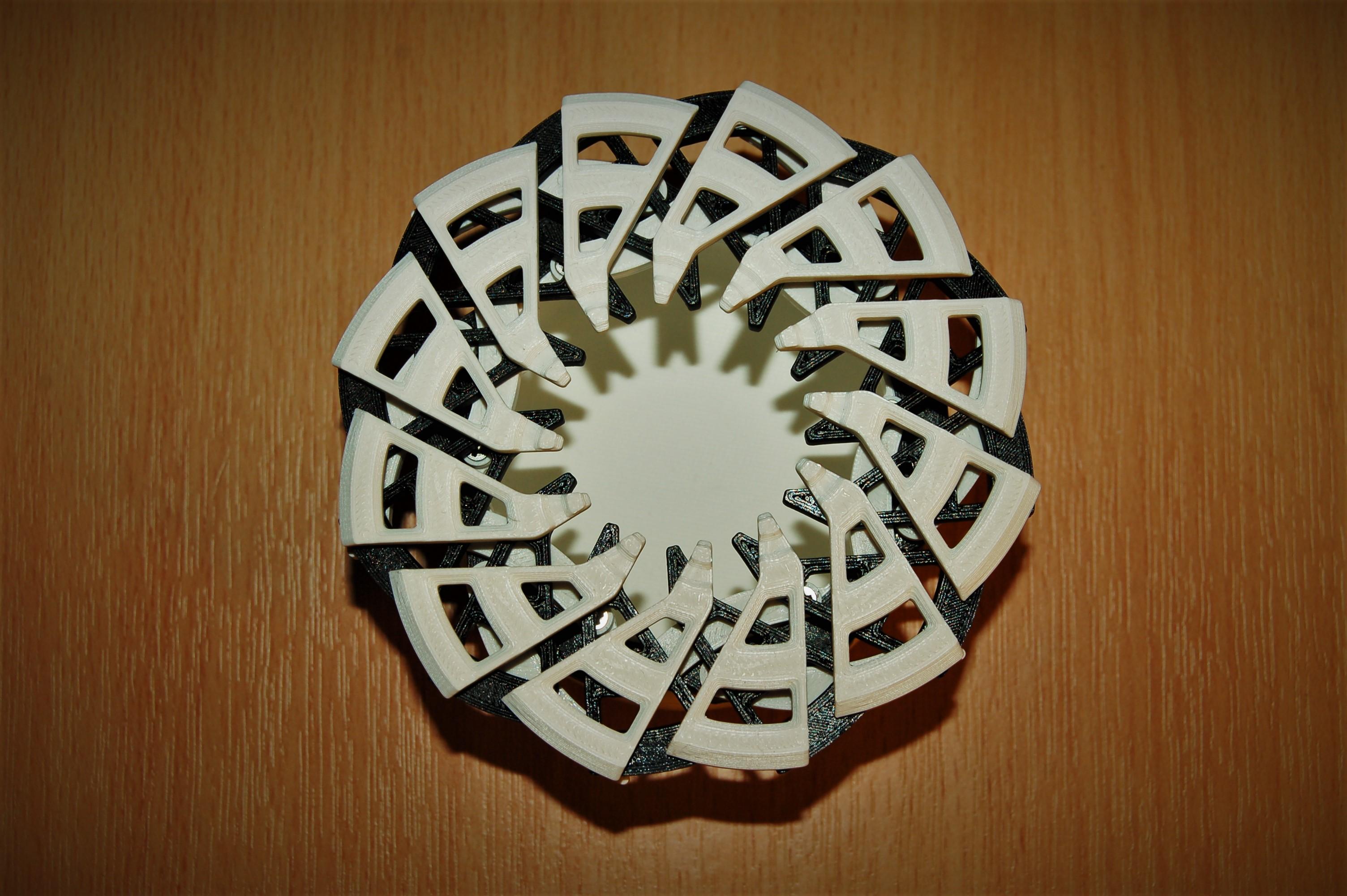
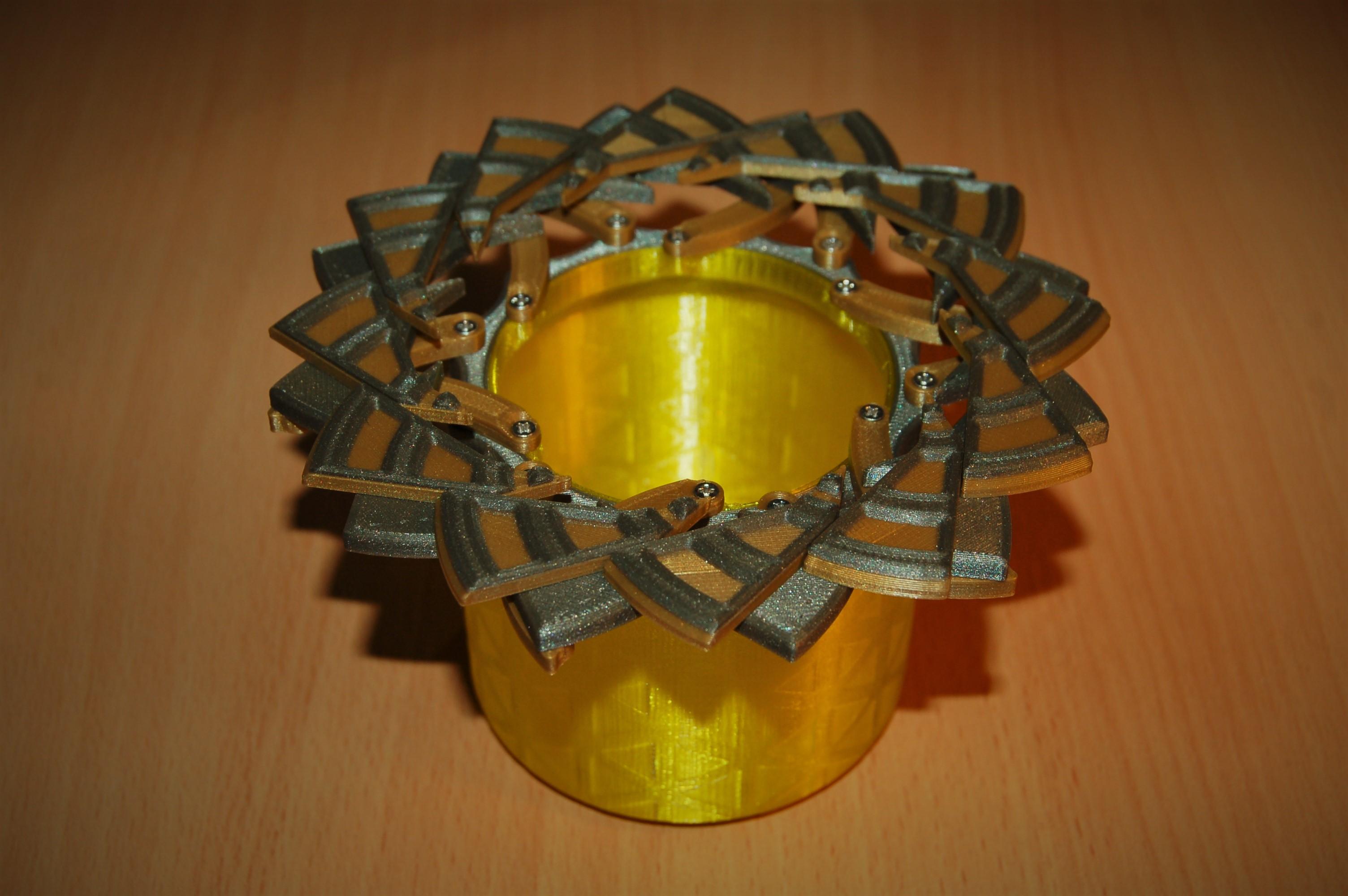
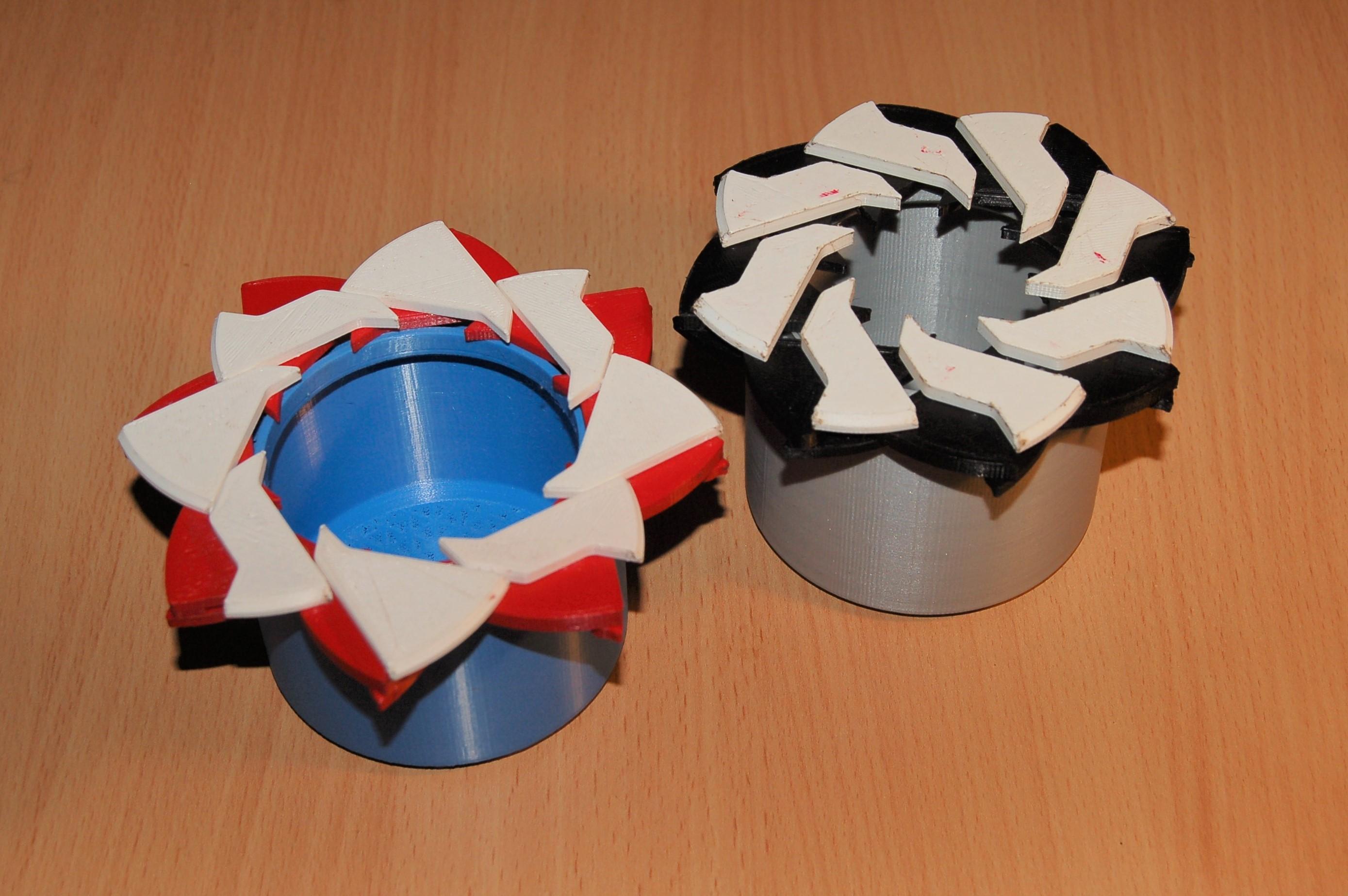
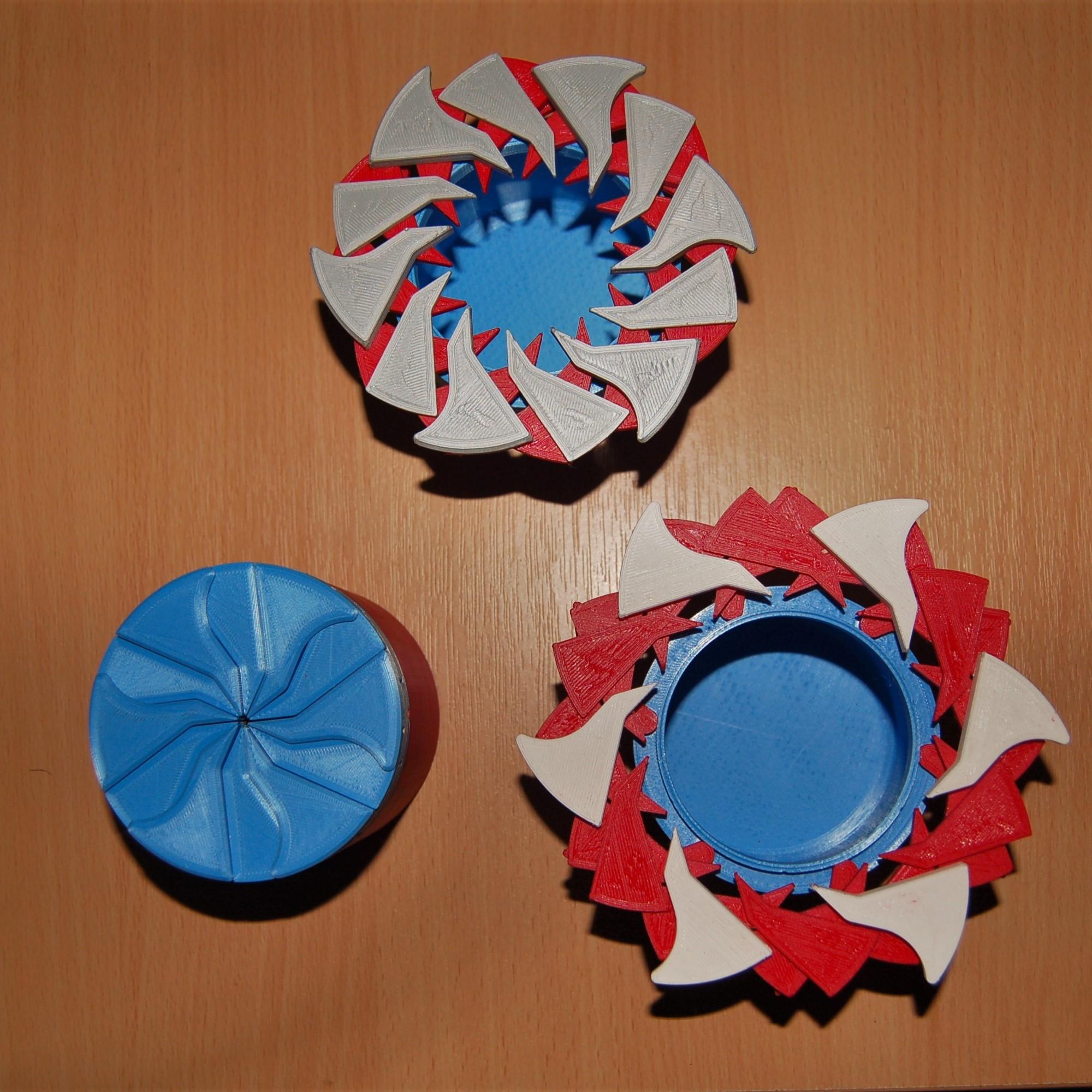
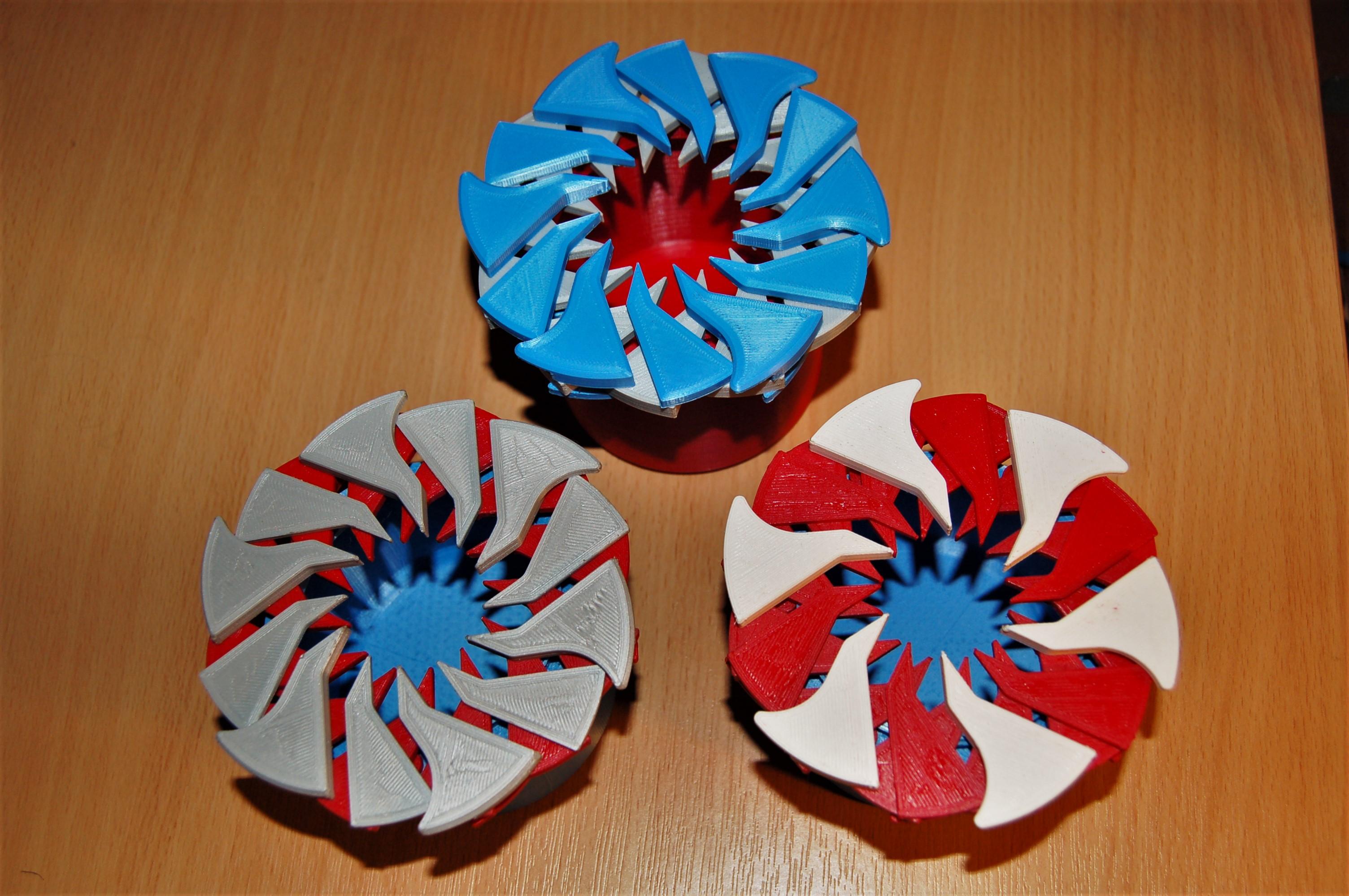
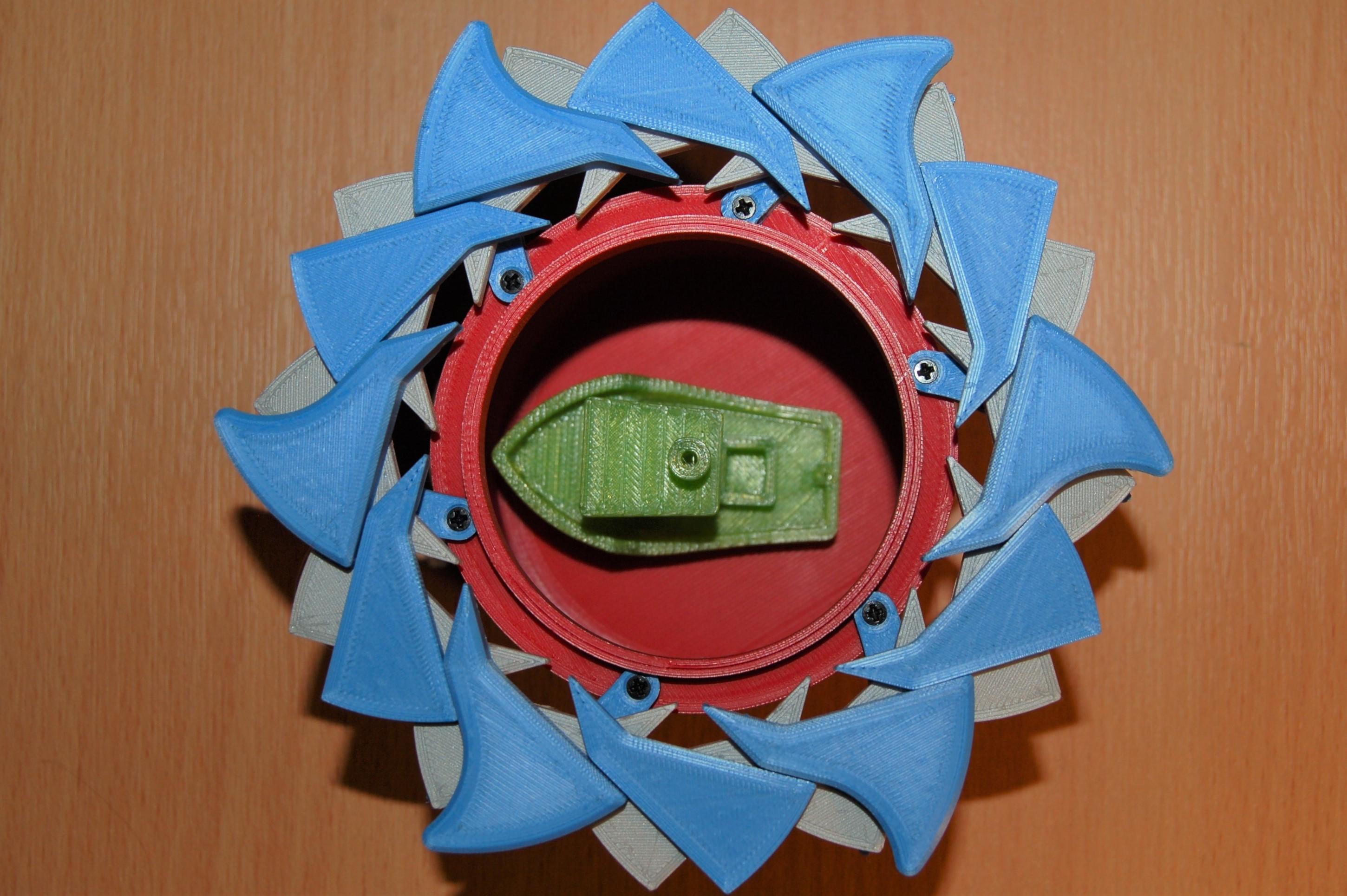
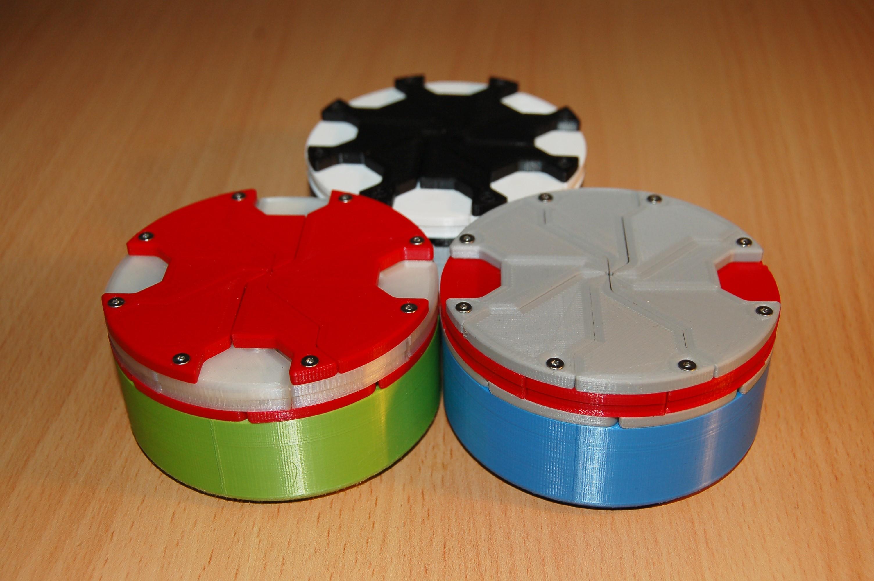
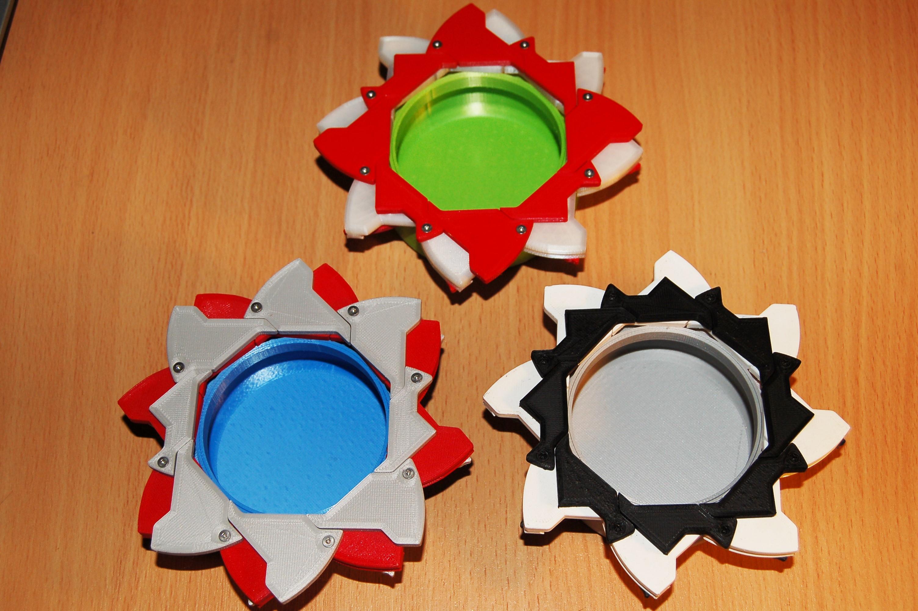
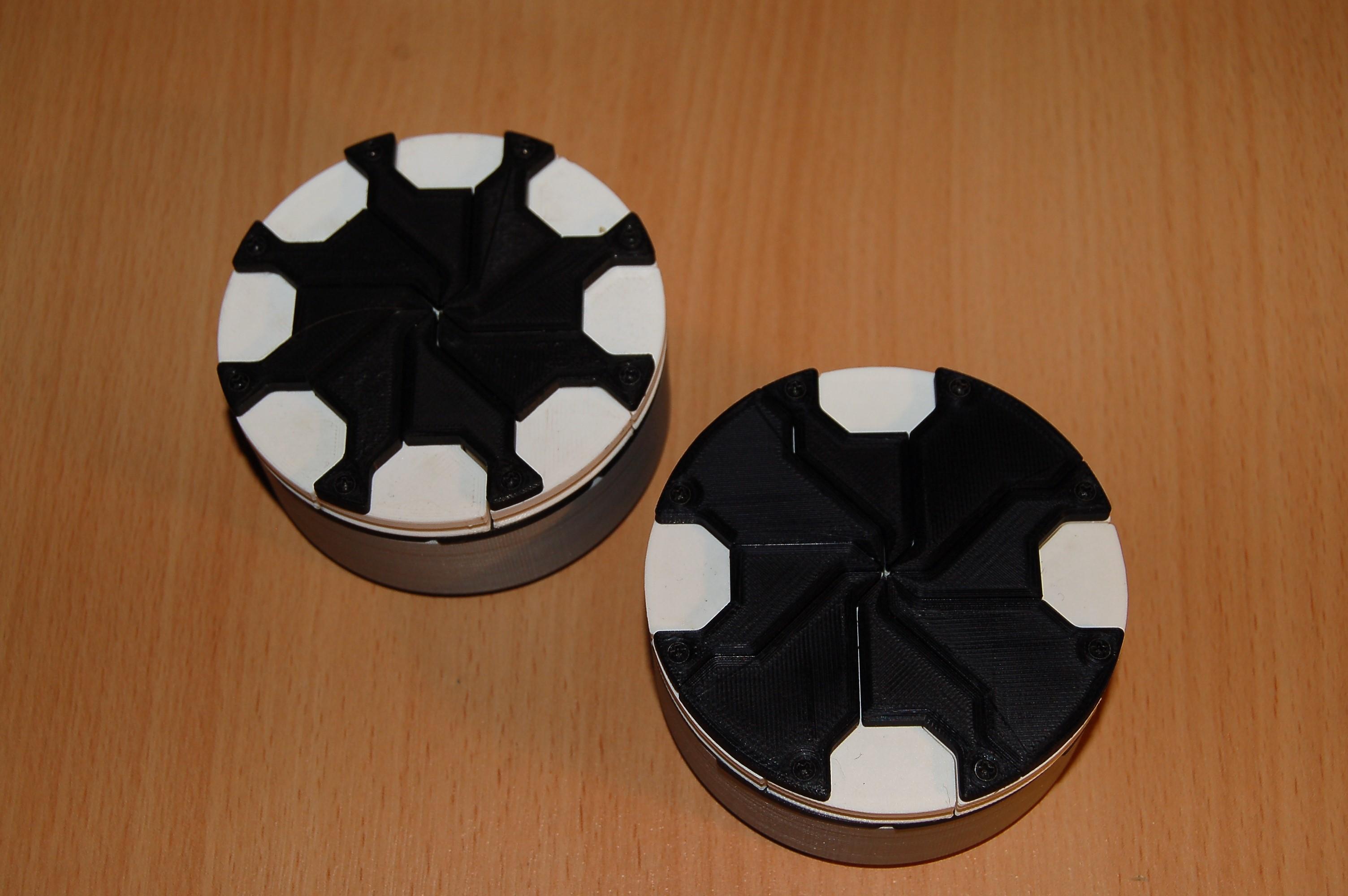
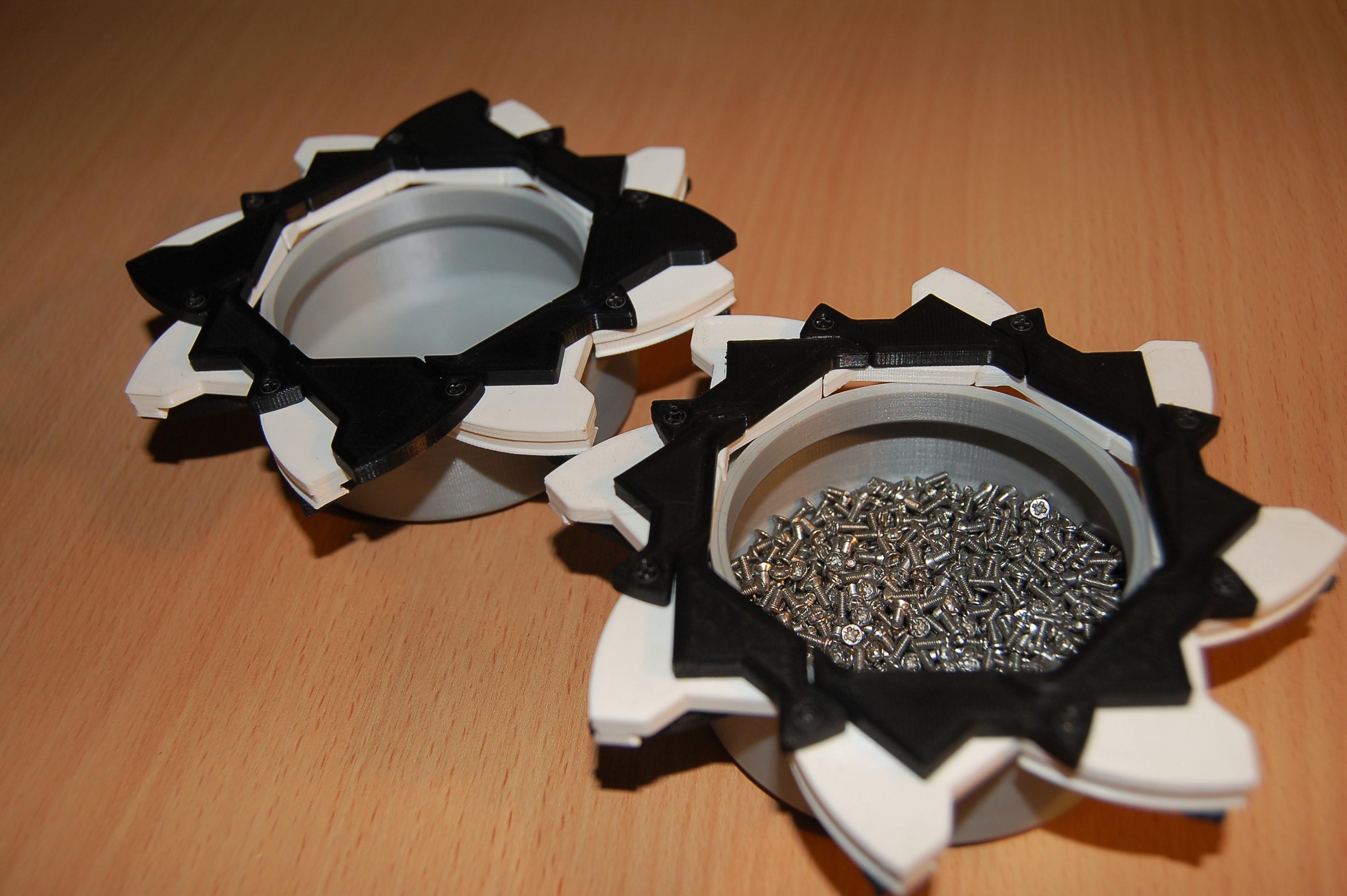
Inspired by the Hoberman Sphere toy, actually long before I had a 3D printer, I realised I could make an iris box mechanism from a slice of it. Turns out this is just a Hoberman mechanism which I reverse engineered from the sphere. These are nice in that no support material is needed to print a fairly complex design but a lot of screws are required; the most complex requires 60 screws for a single box!
- Octo-box. My second ever box design, with two layers of eight petals (hence octo in the name). This also does not require screws but again specific layer heights are needed for the clip together pins and holes.
- Dodeca-box. A more complex 12 petal version of the octobox. Again no screws are required but care needs to be taken when assembling since it is hard to separate the parts after clipping them together.
- Octo-box V2. The improved version of the Octo-box. A nice feature is that it forms a neat octagonal aperture when opened. 40 screws required.
- Dodeca-box V2. The improved Dodeca-box is not as neat as the Octo-box in my opinion but it is more impressive mechanically and the aperture opens almost wider than the box itself! 48 screws required.
- Octo-Iris Box. The next stage in the iris box evolution was to adjust the mechanism to incorporate an opening twist collar. This freed up the top of the lid (along with the other designs), to add decorative patterns. This is one of the most popular designs, likely because it is easy to print and relatively simple (and it looks cool). 48 screws required.
- Dodeca-Iris Box. Perhaps the most complex mechanical design, again it incorporates an opening collar and more decorative lids. Requires 60 screws to assemble (I buy screws in the hundreds since all my designs use the same type, M2x6 countersunk).
Aperture Boxes
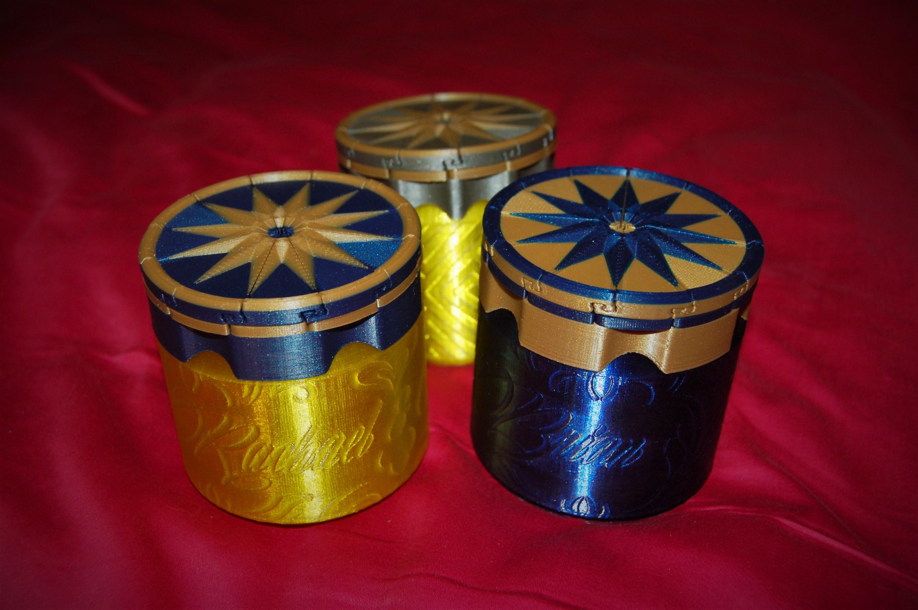
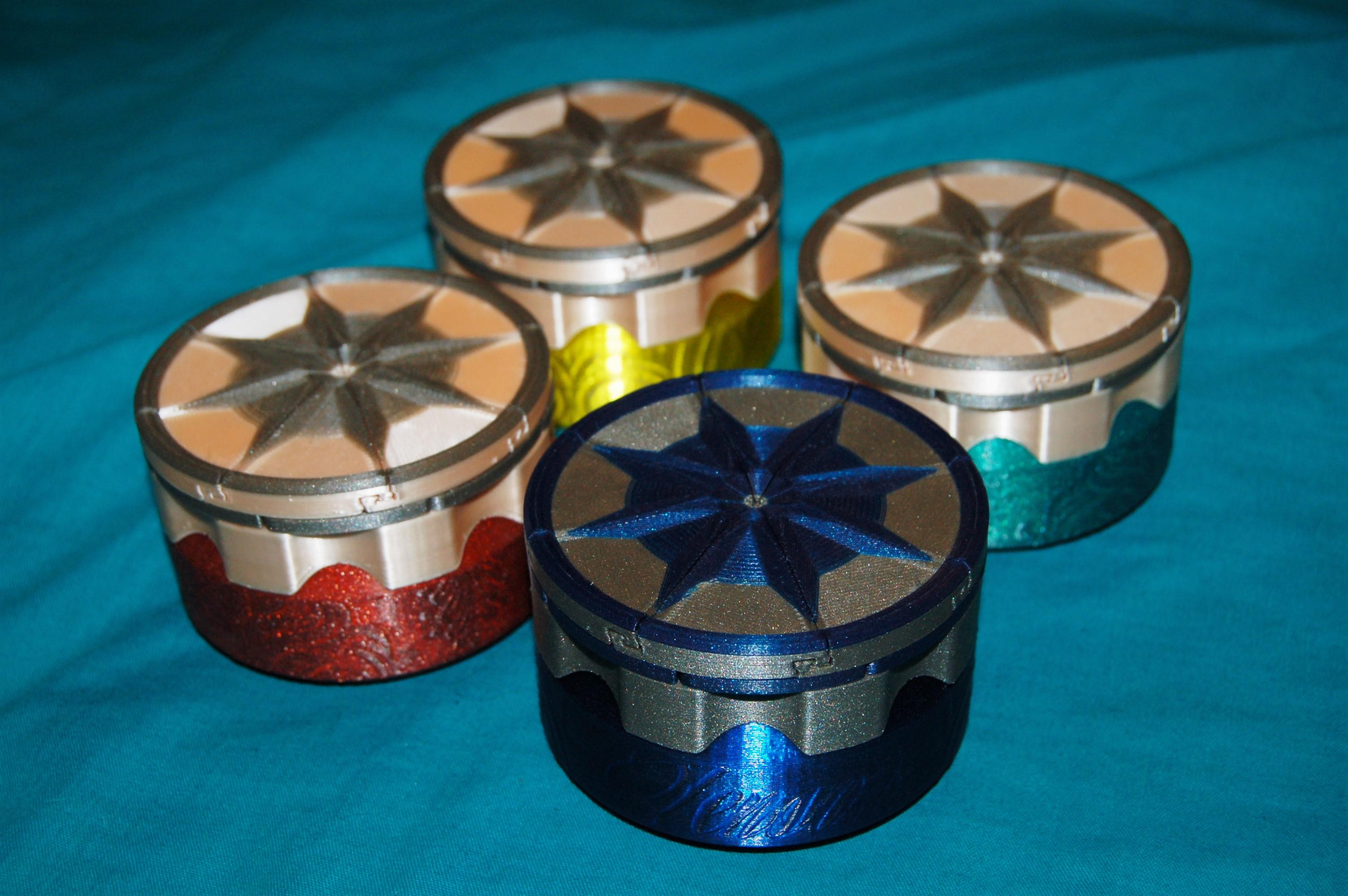
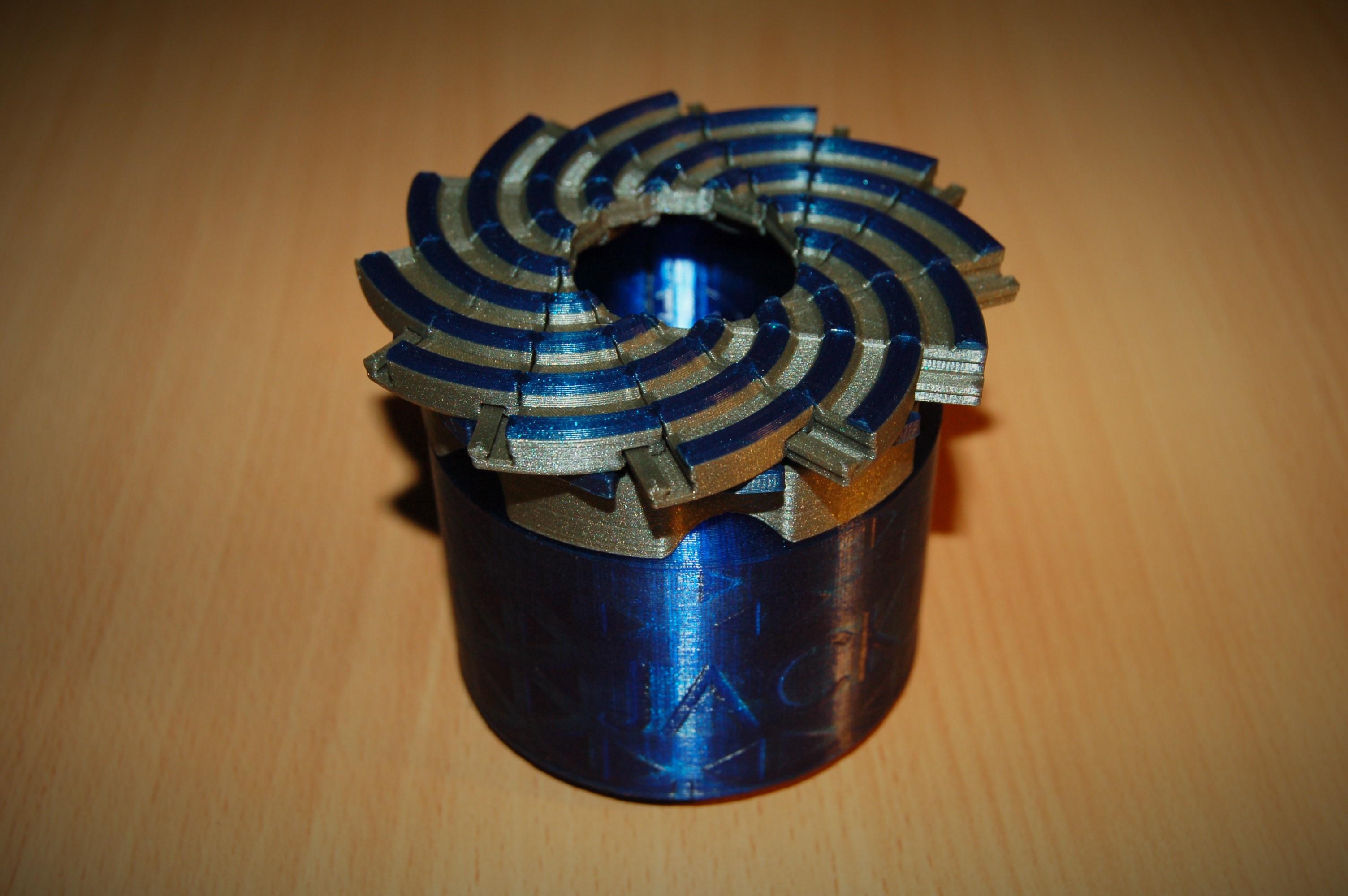
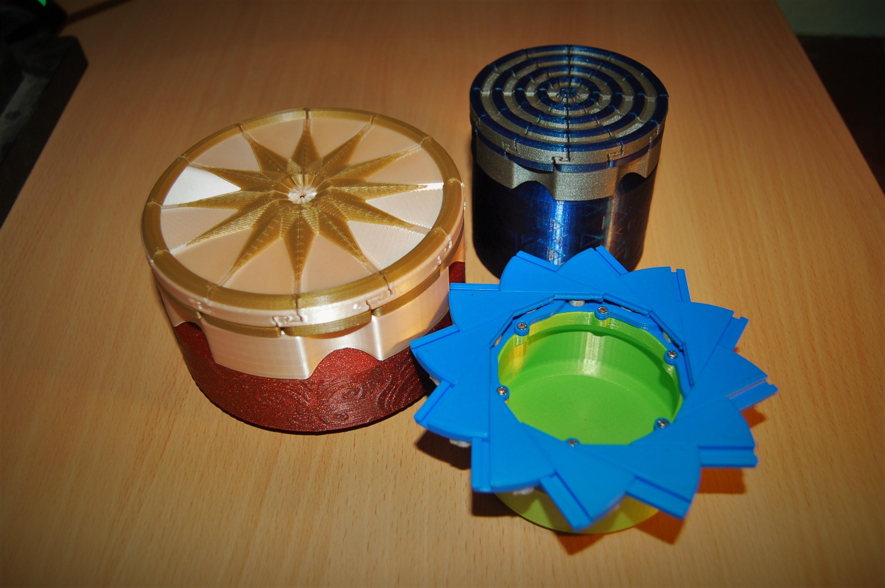
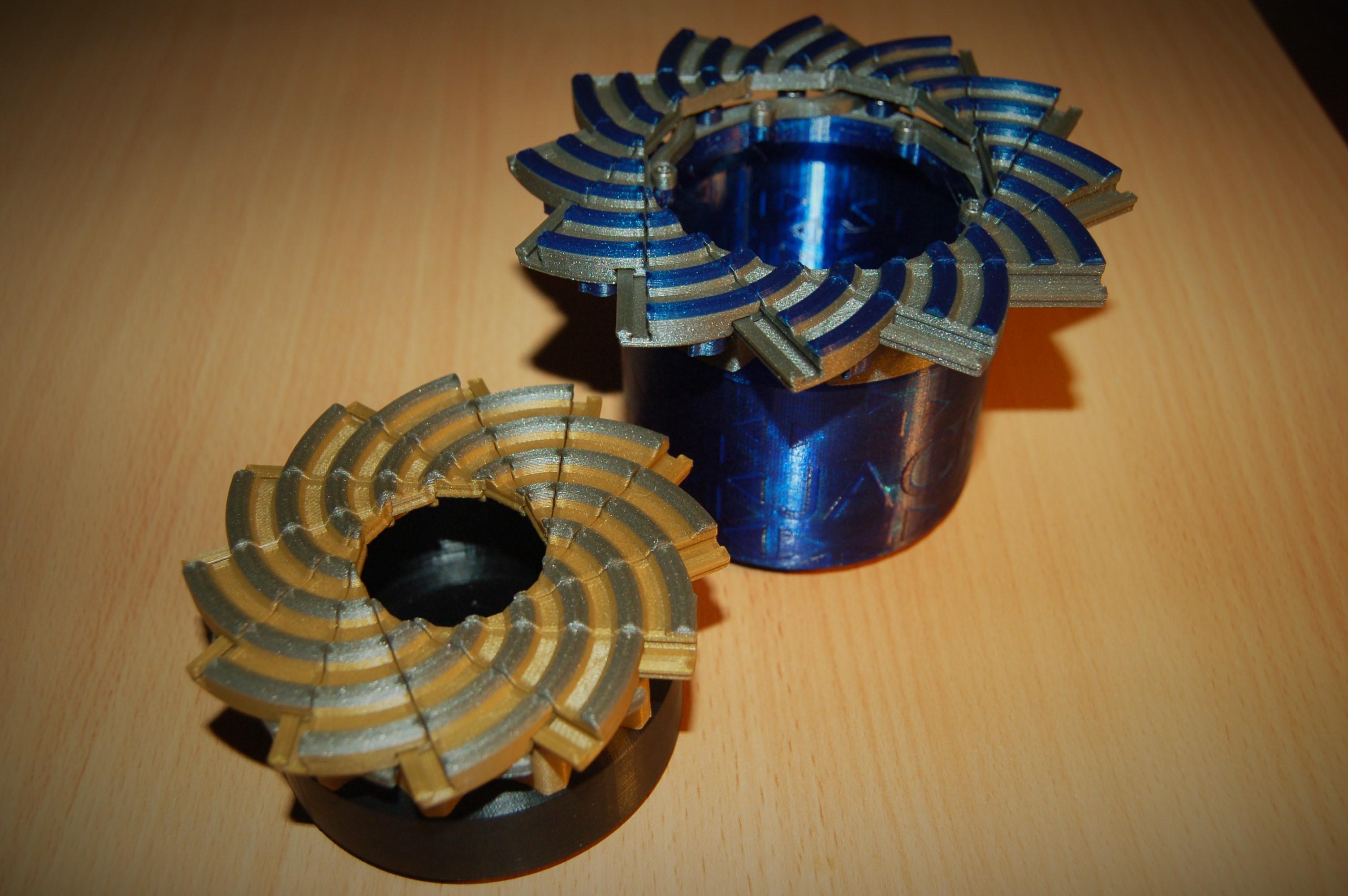
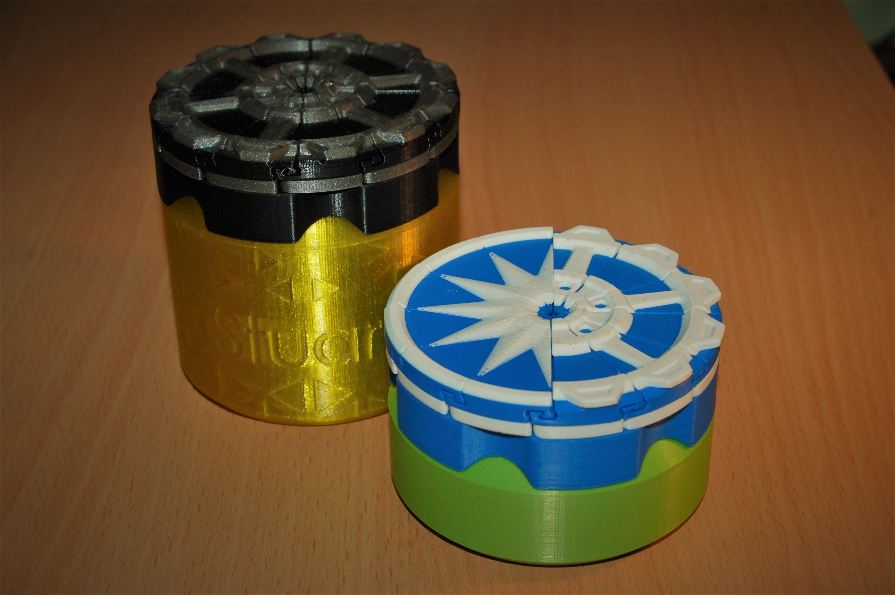
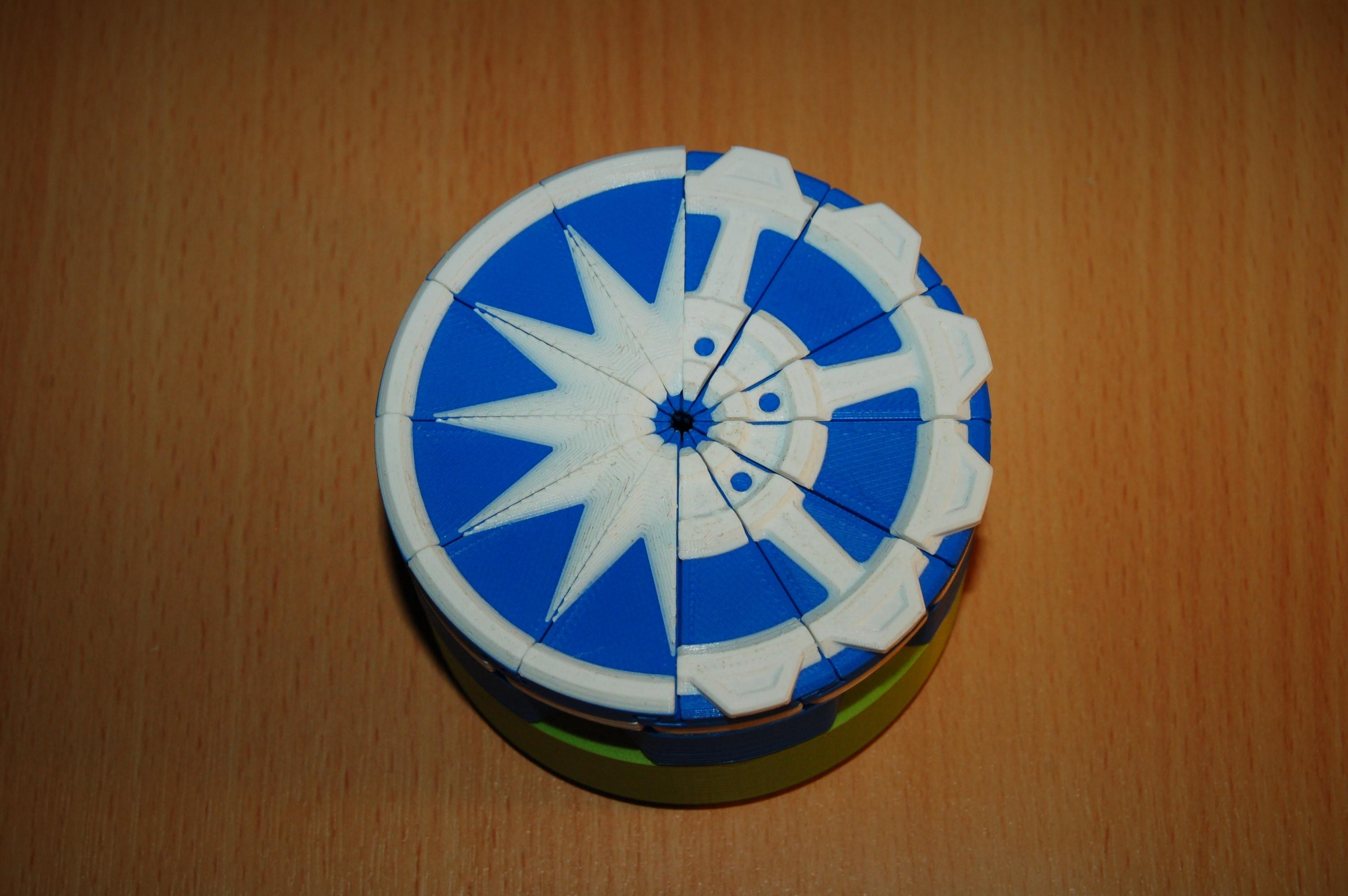
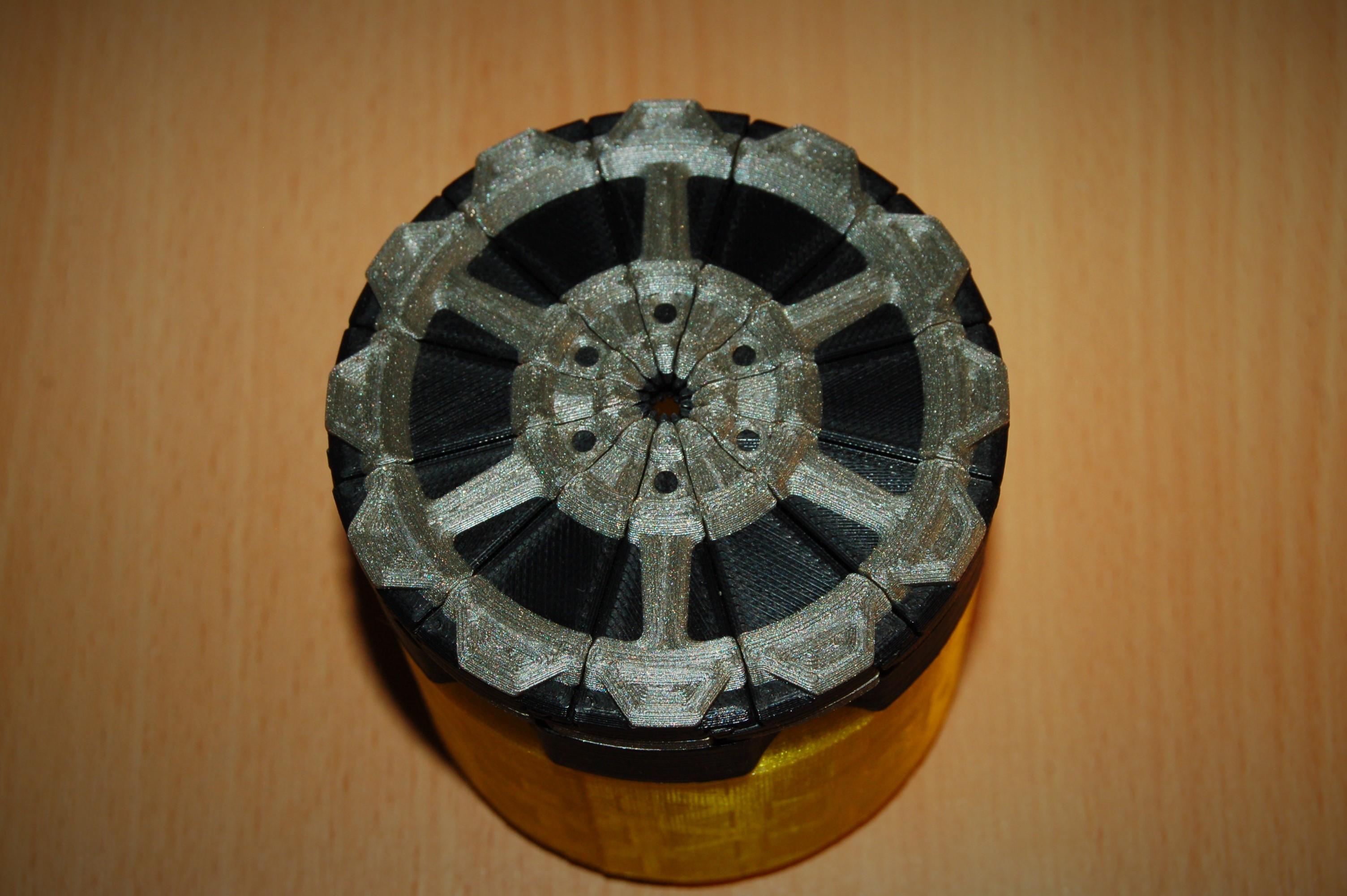
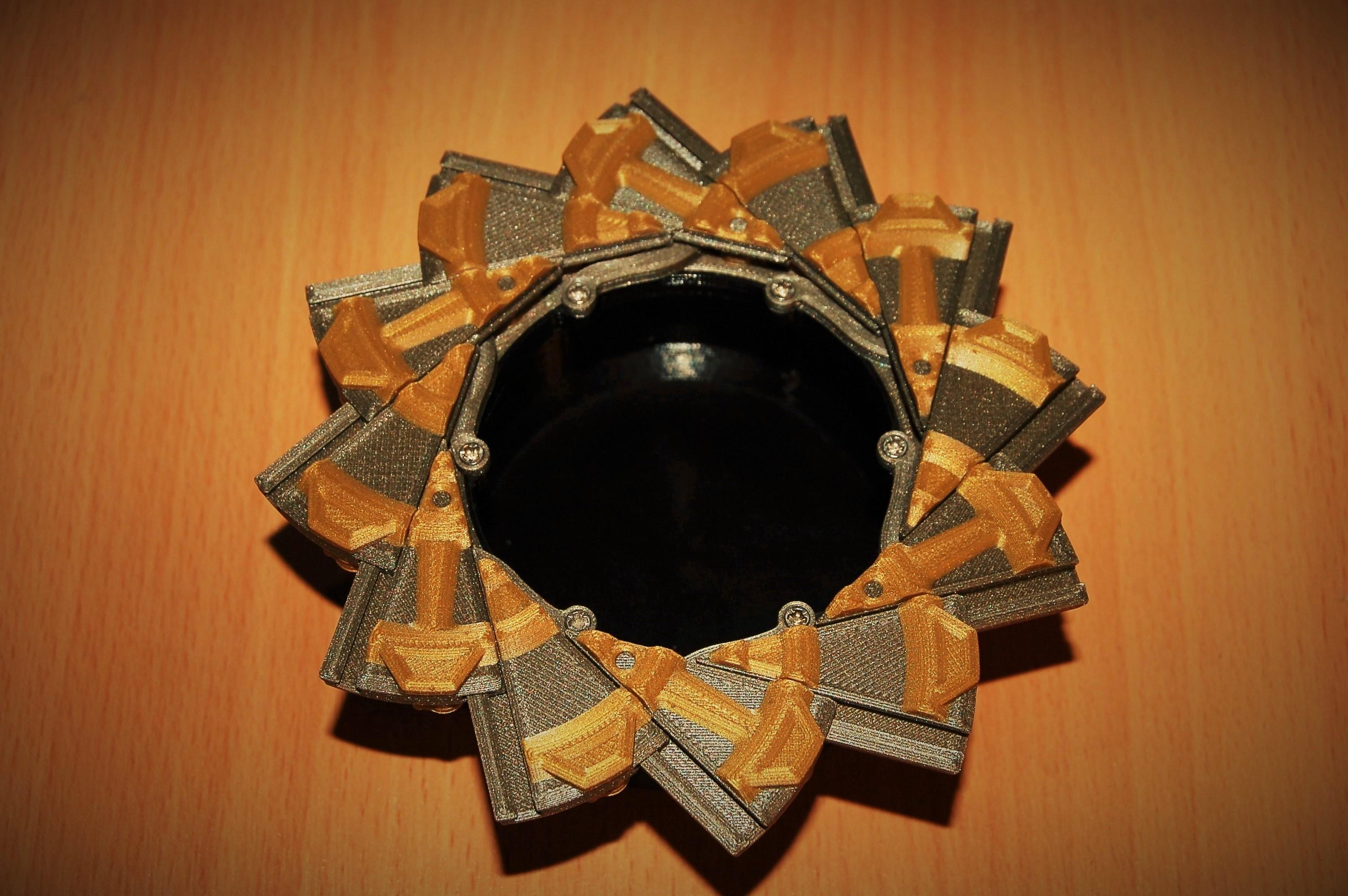
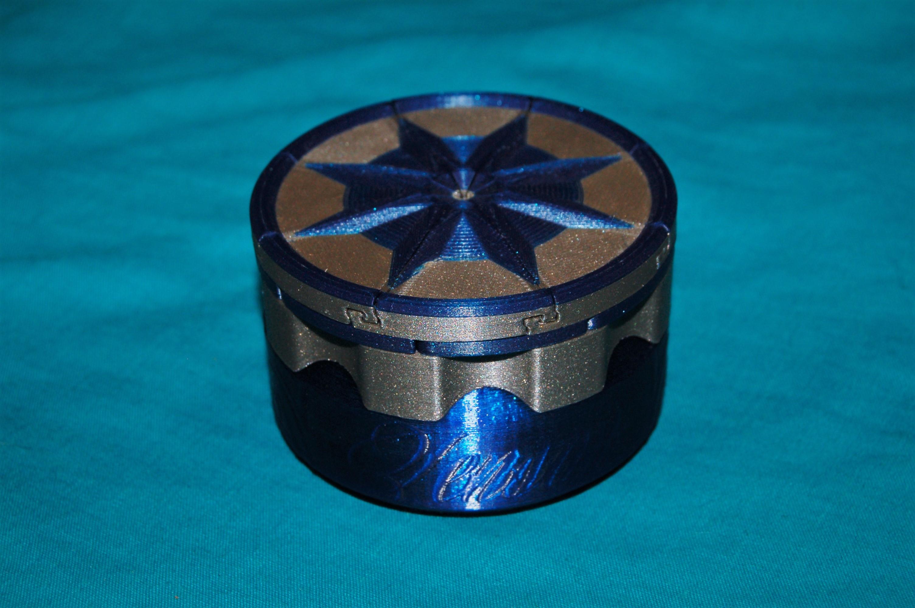
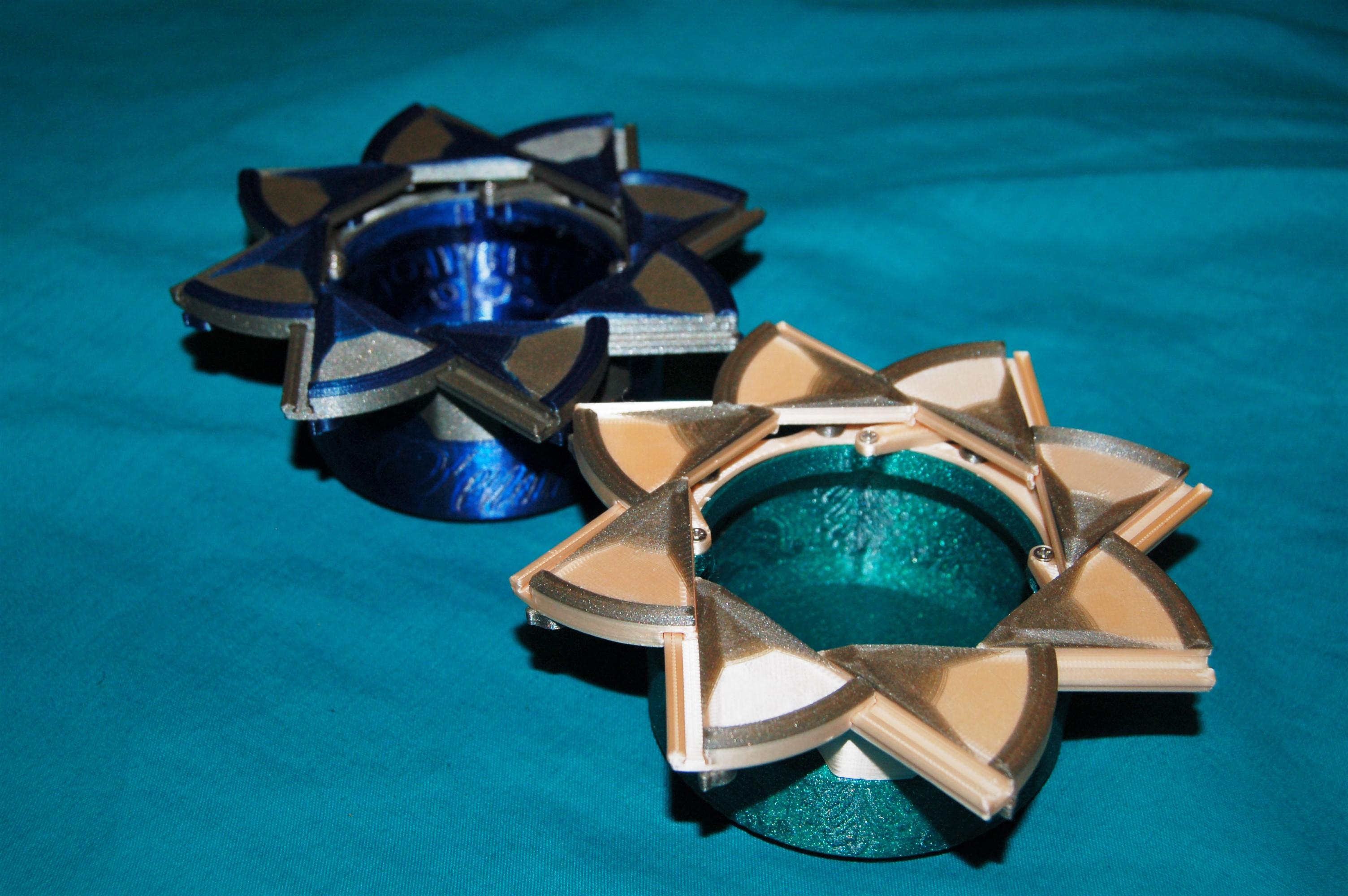
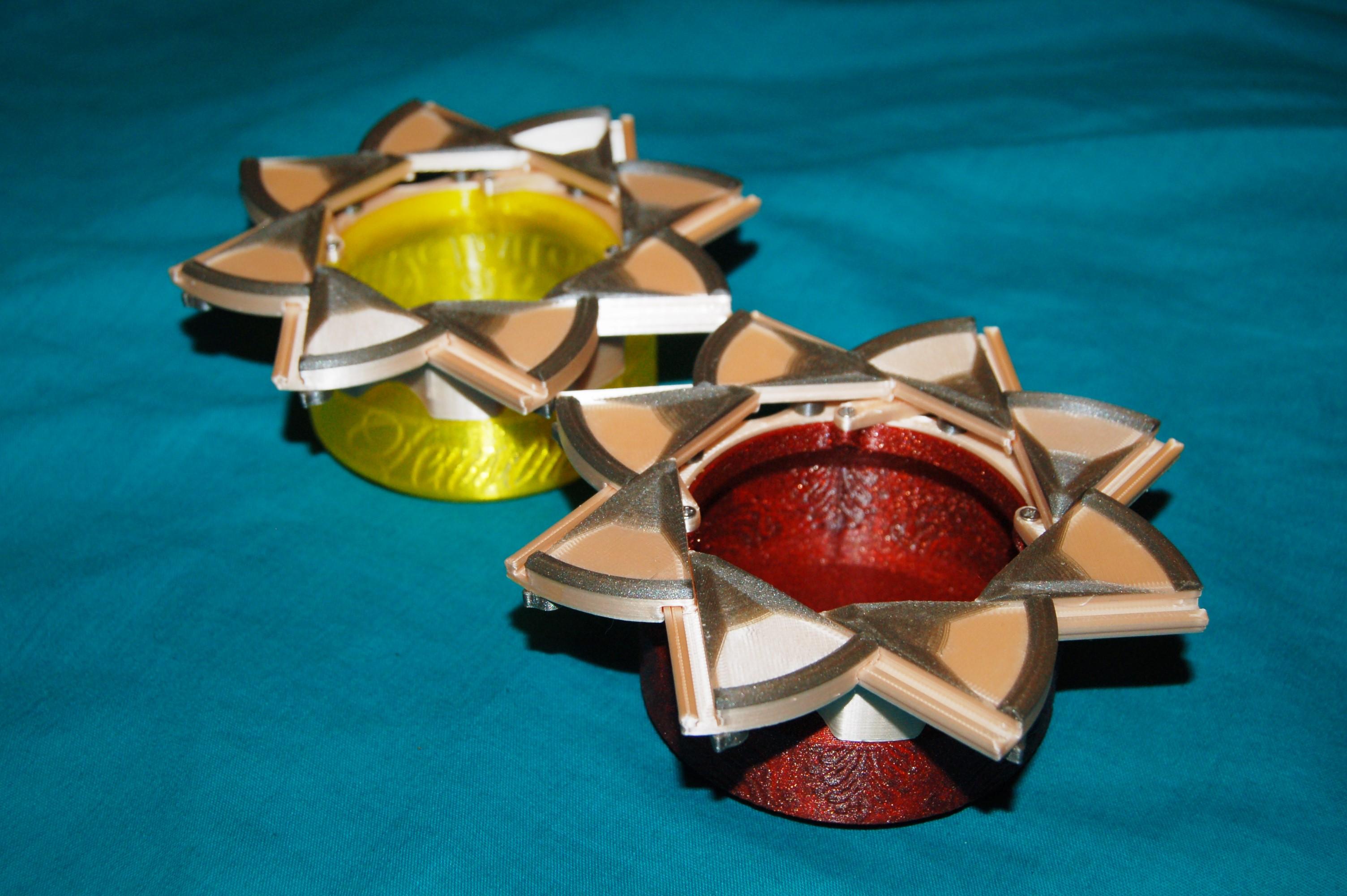
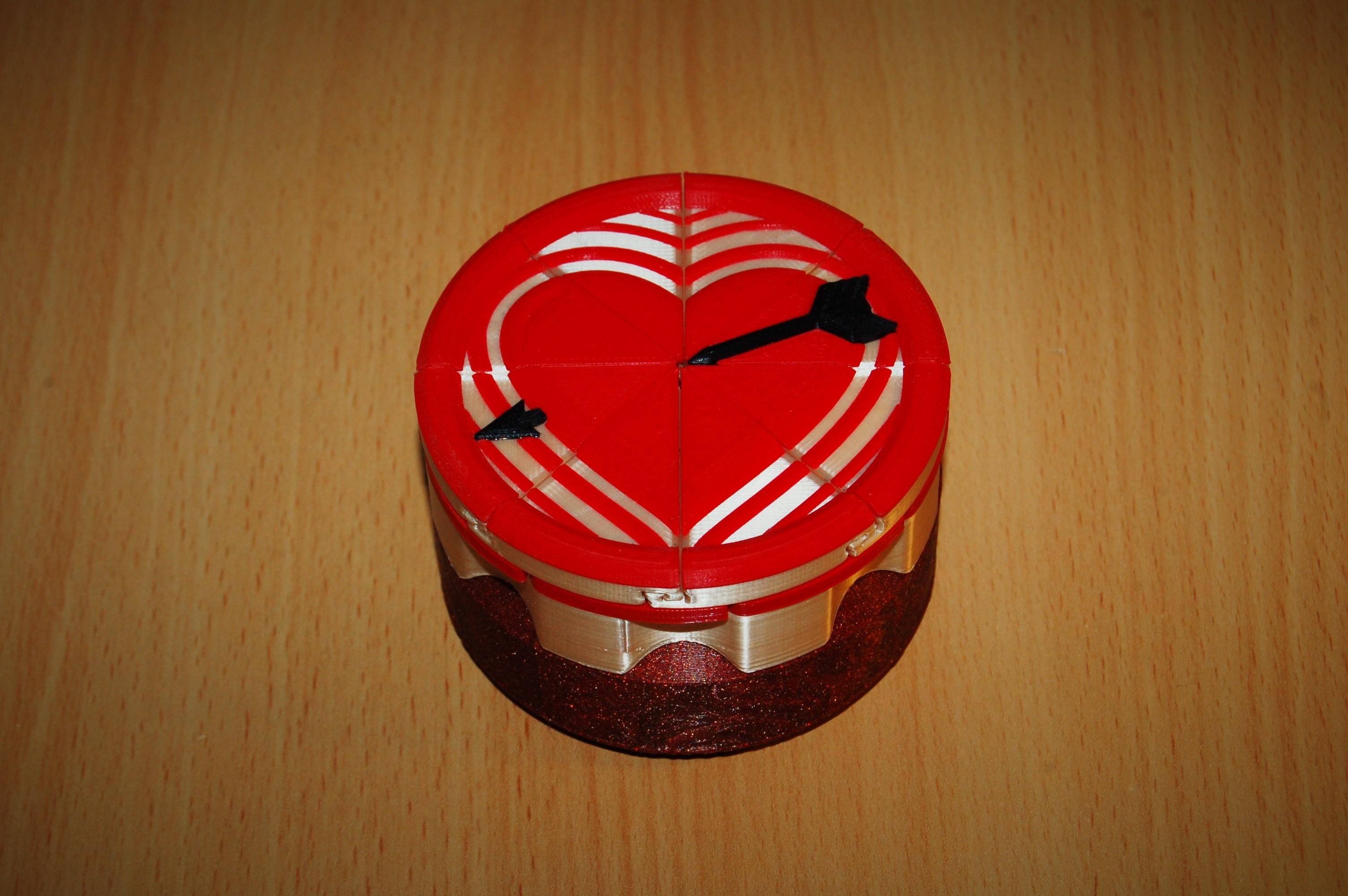
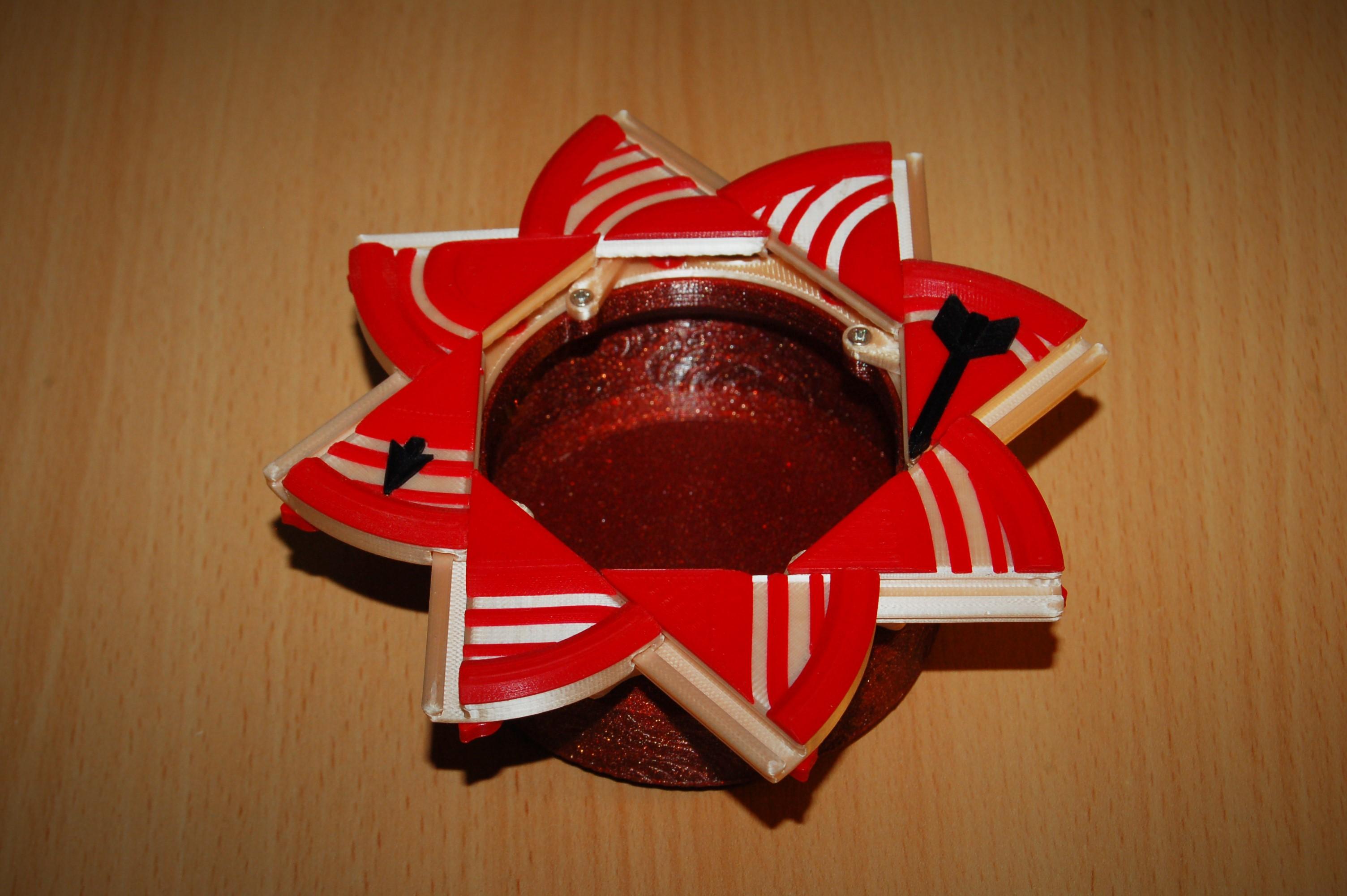
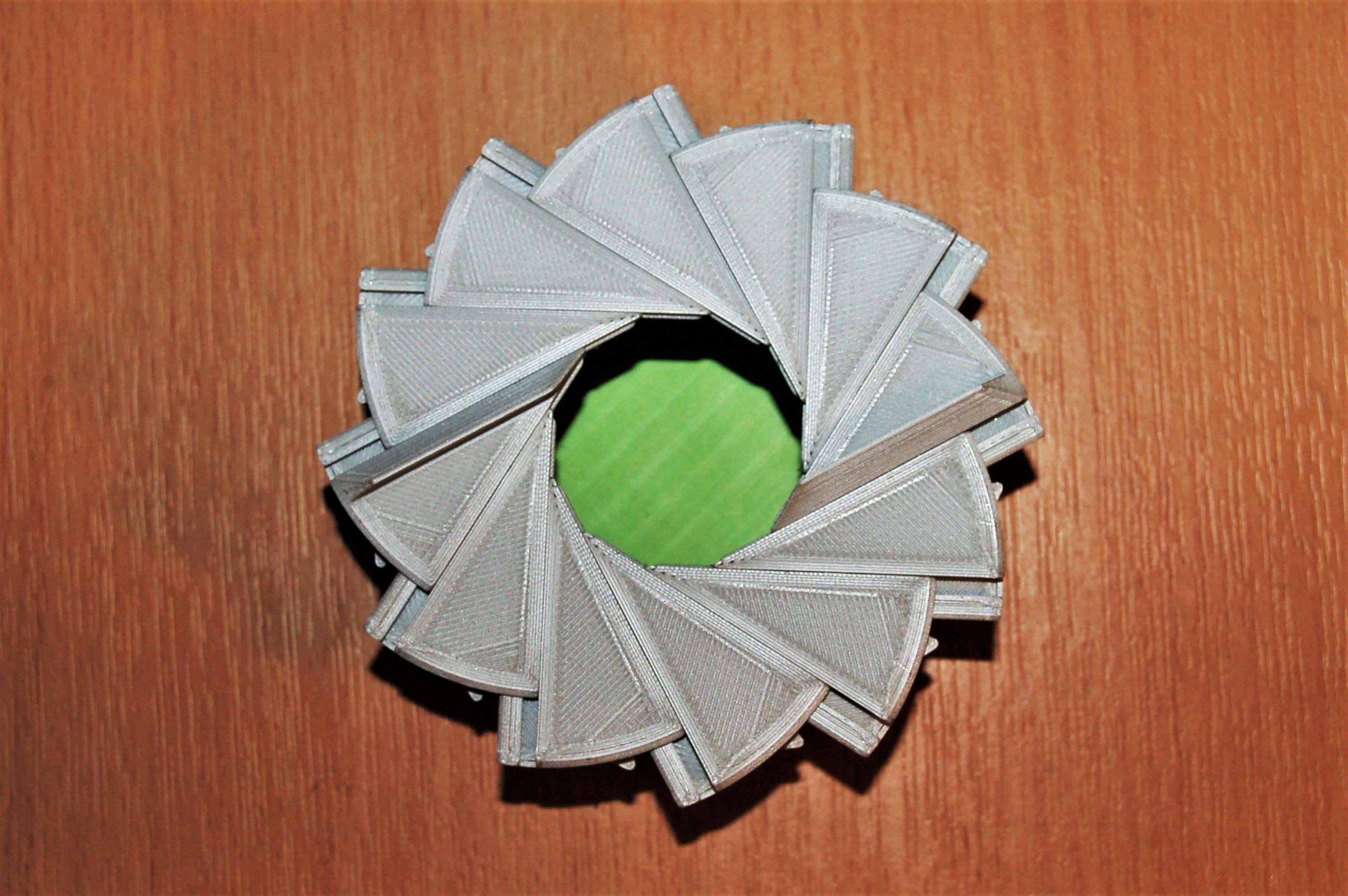
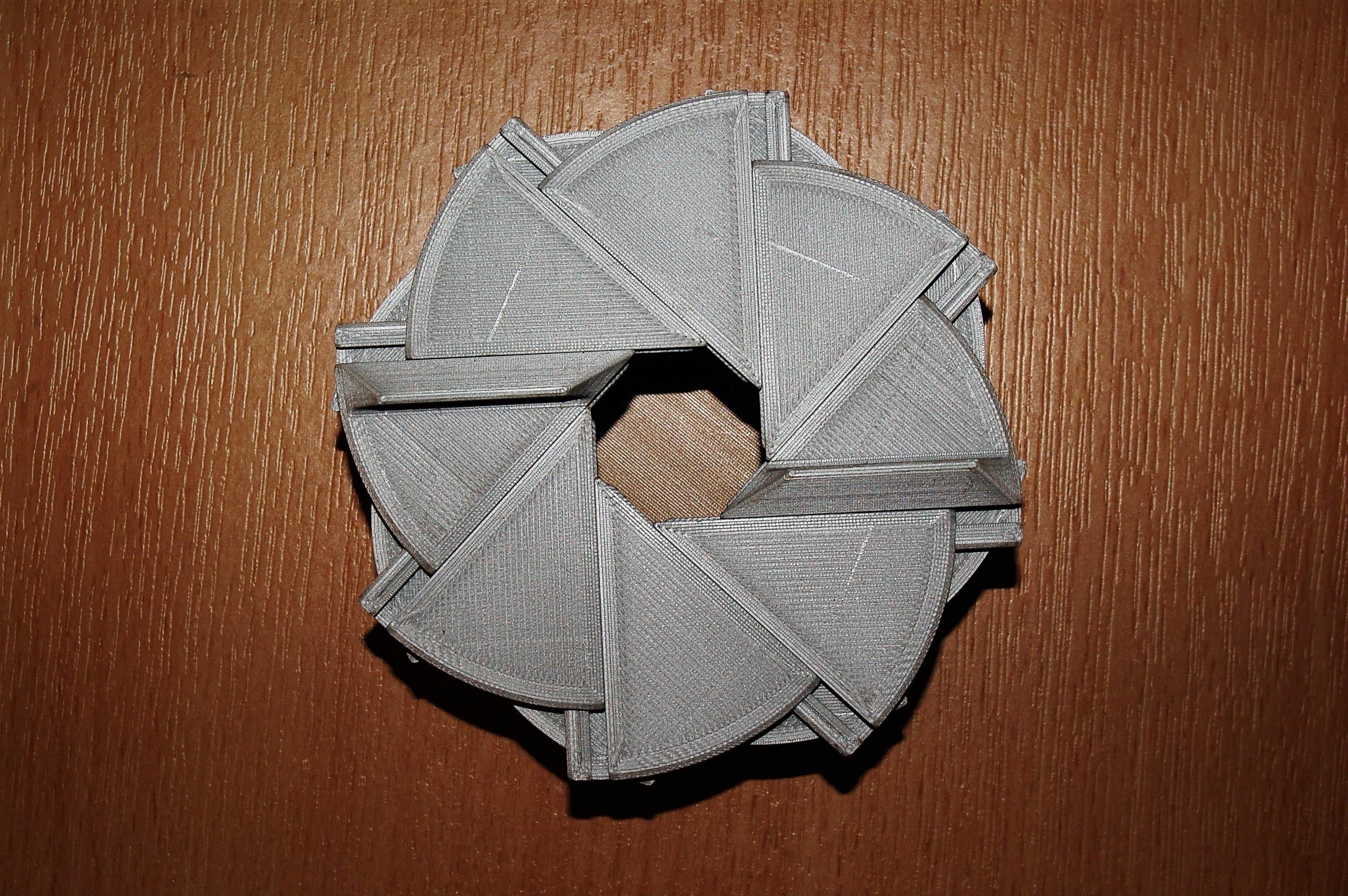
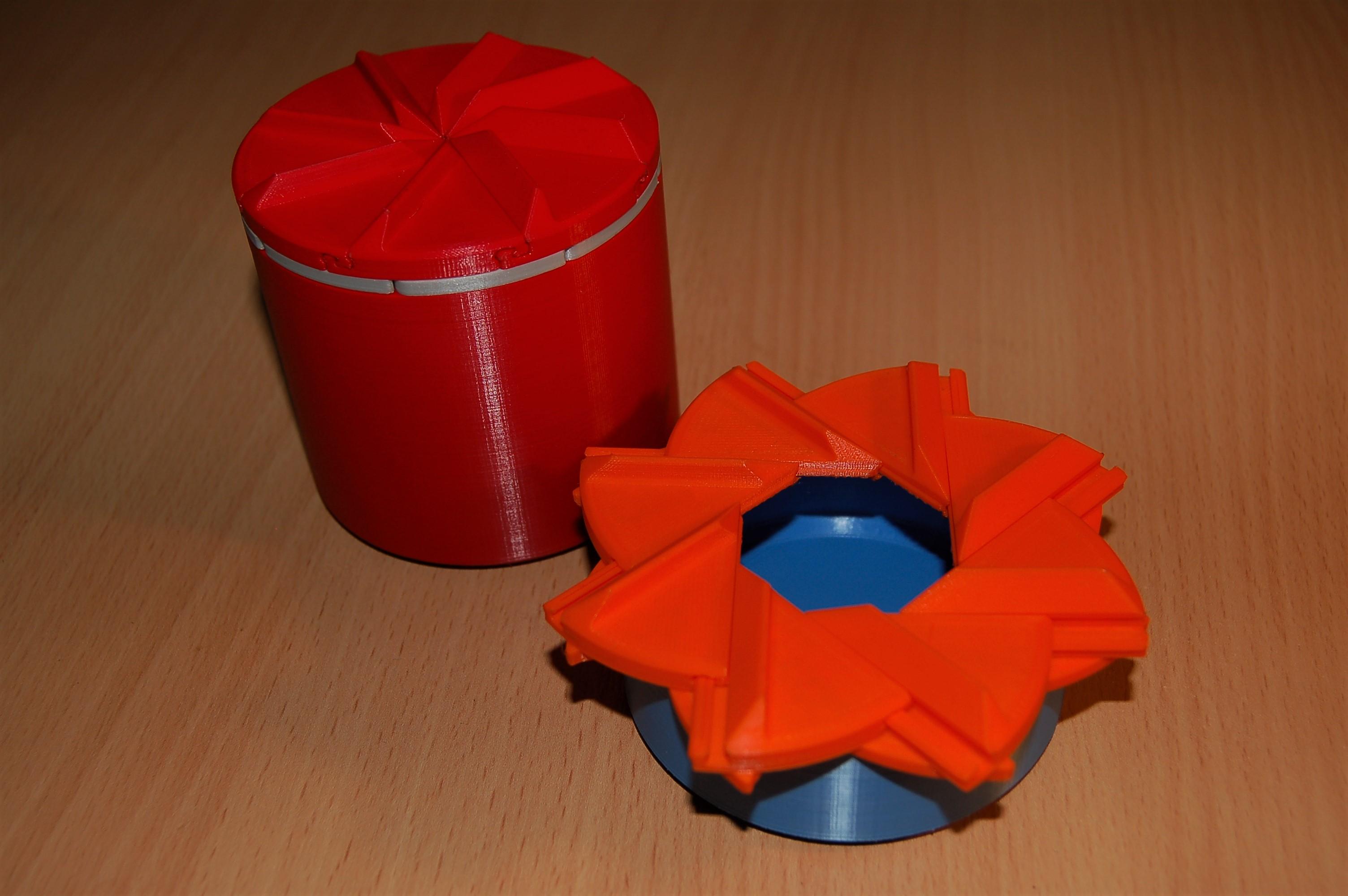
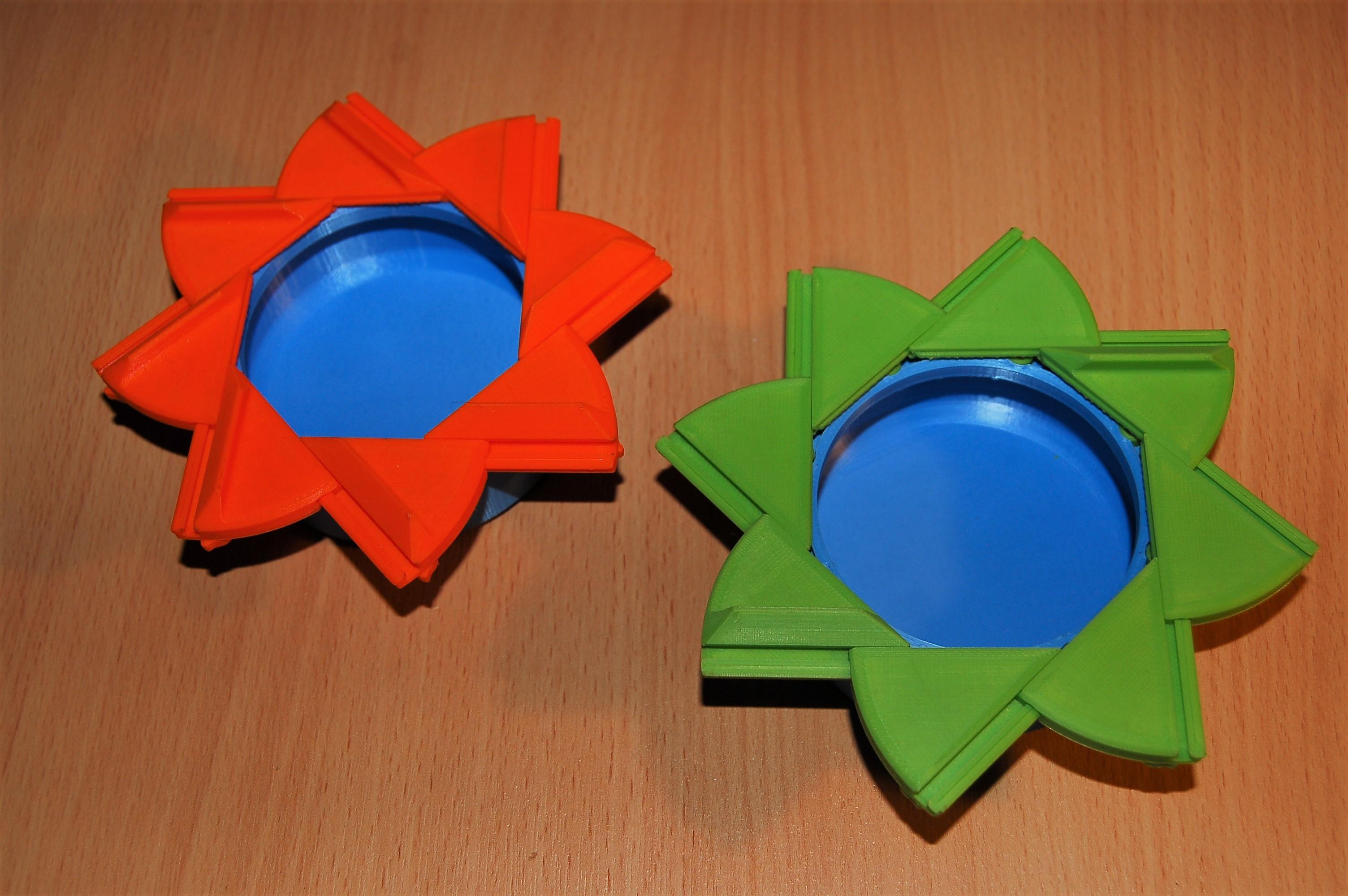
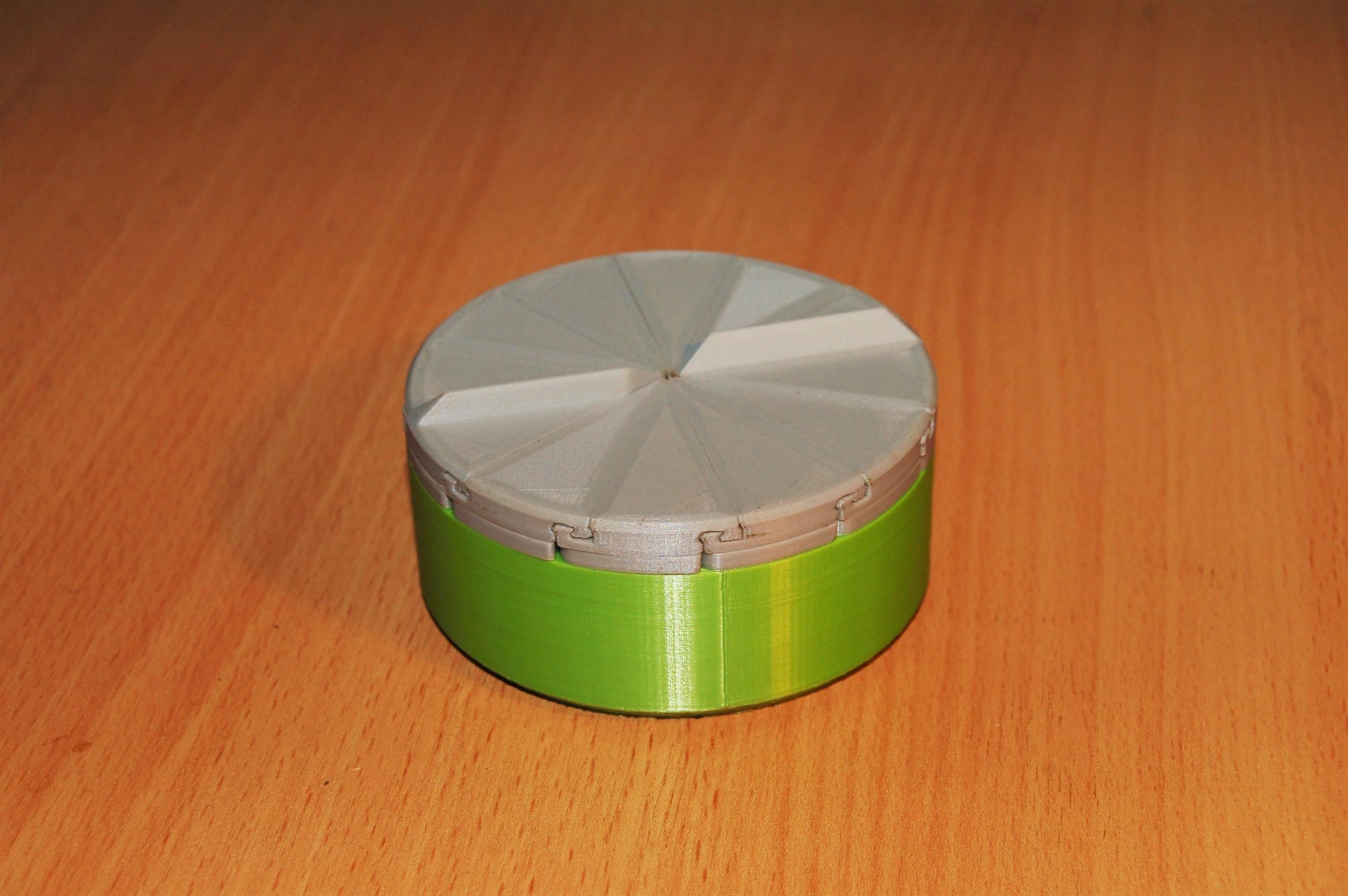
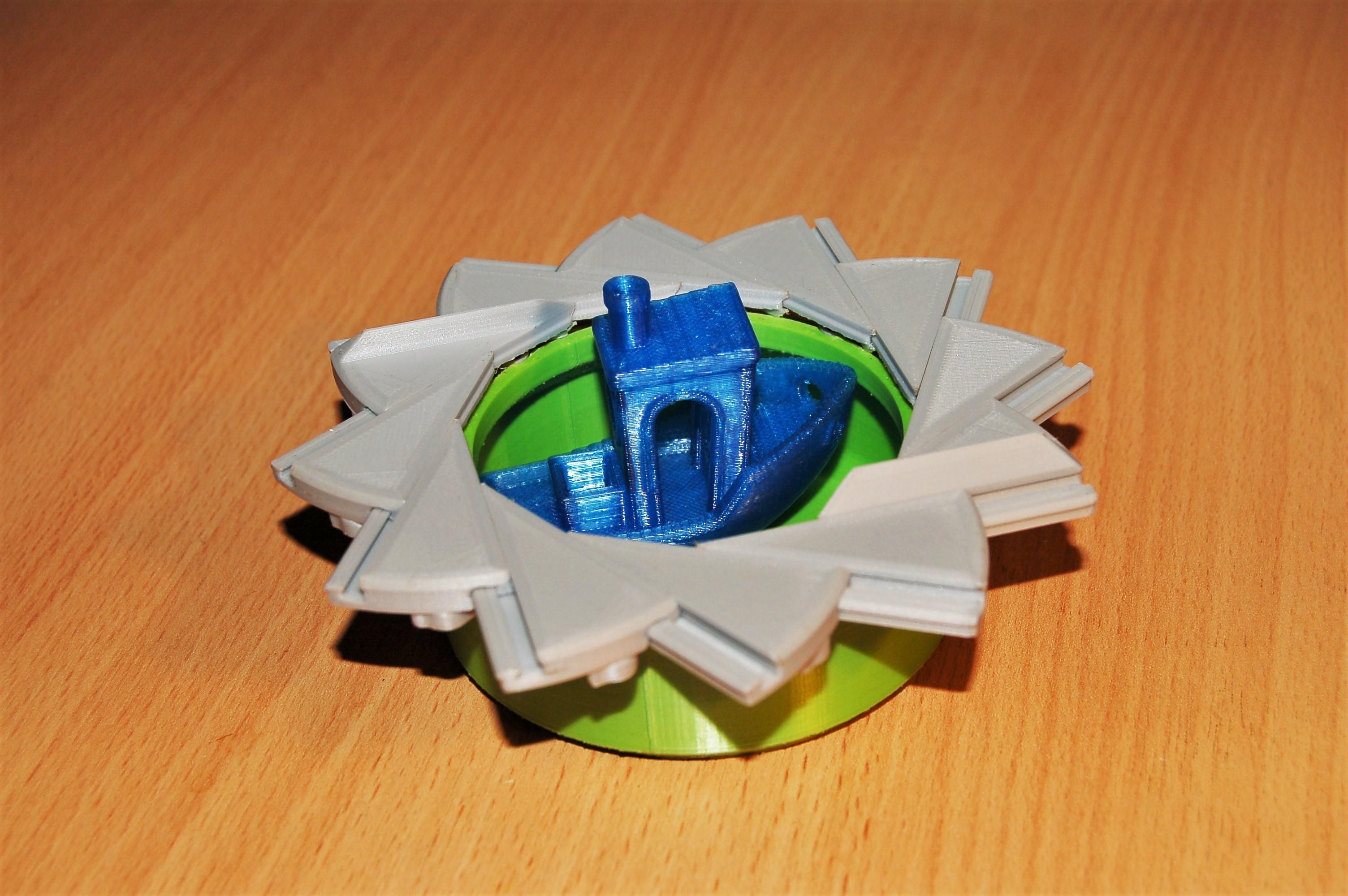
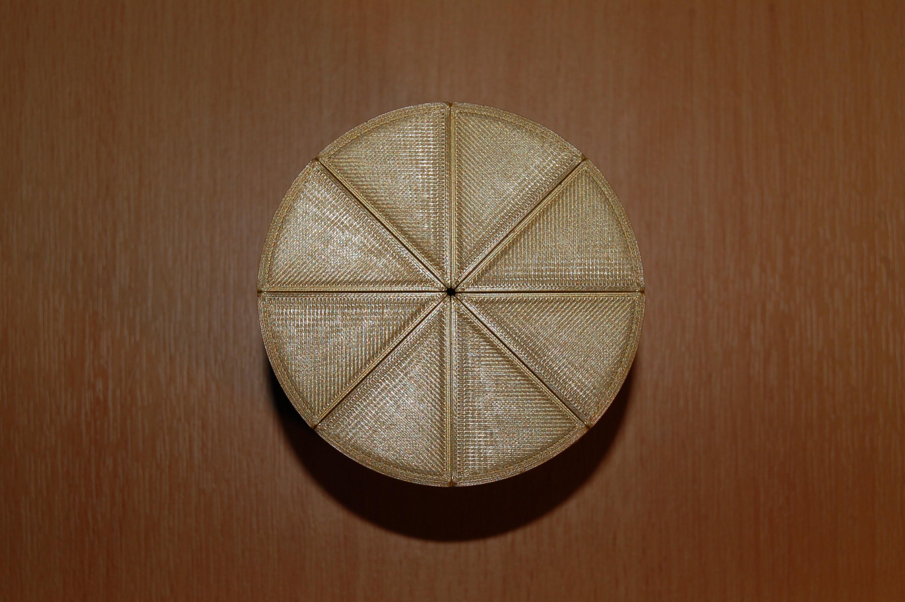
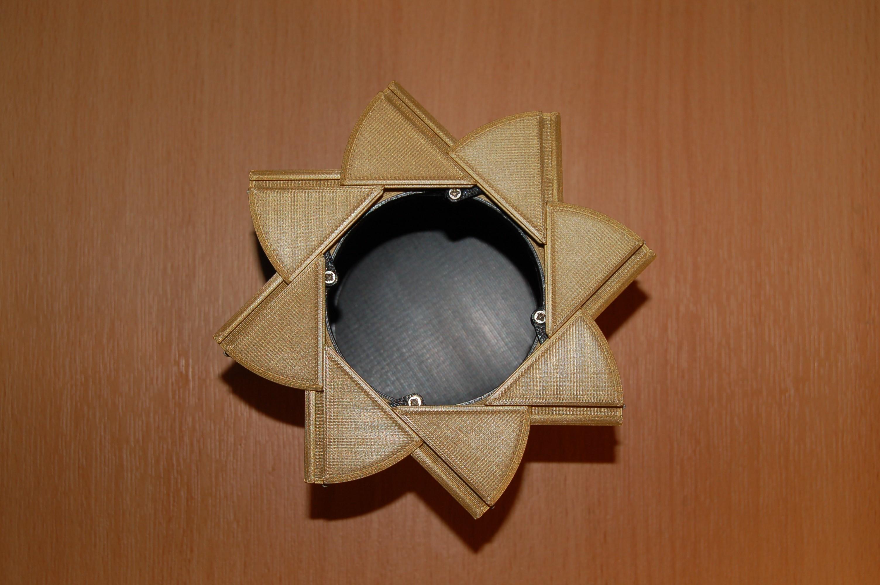
This family of boxes produce an expanding circular(ish) aperture, although using a unique mechanism of dovetail joints between the doors and links to join them to the container. These require less screws than my other designs but are a little more tricky to print since supports are required on the dovetails and 'Contour compensation' is sometimes needed when slicing to get a neat final assembly.
- Aperture Box. The original version, so named because it is essentially a moving version of the Aperture Science logo from the Portal universe; hence the orange and blue version of the box I made ;). 16 screws required.
- 12 Leaf Aperture Box. A more complex version which has 12 sliding doors producing a fairly circular aperture. There is not much in the way of decorative features on this design (along with the Aperture box) since the top had to be reserved for the opening handles. 24 screws required.
- Aperture Iris Box. By incorporating an opening twist collar, I could produce more decorative lids including the Valentines lid. This design is easier to get a neat final assembly, although less impressive mechanically than the 12 leaf version. 24 screws required.
- 12 Leaf Aperture Iris Box. The 12 door version of the box, it is one of the more tricky to print to a high quality but has some of my favourite lid designs including the 'Hypno Spiral' and the 'Gear Lid'. You may recognise one of the box lids, since I made it into my logo with some amateur photoshopping (that lid ironically is made up of test prints). 36 screws required.
Support Material
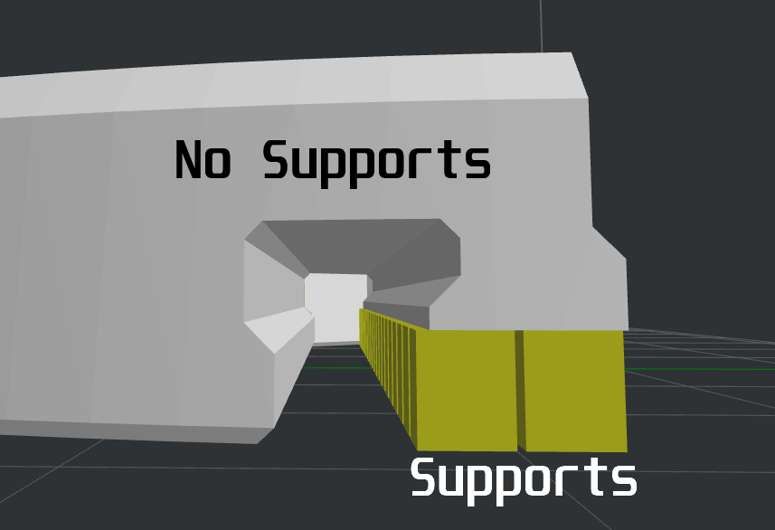
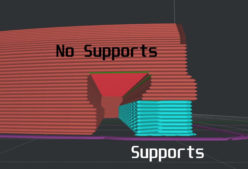
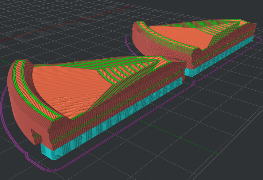
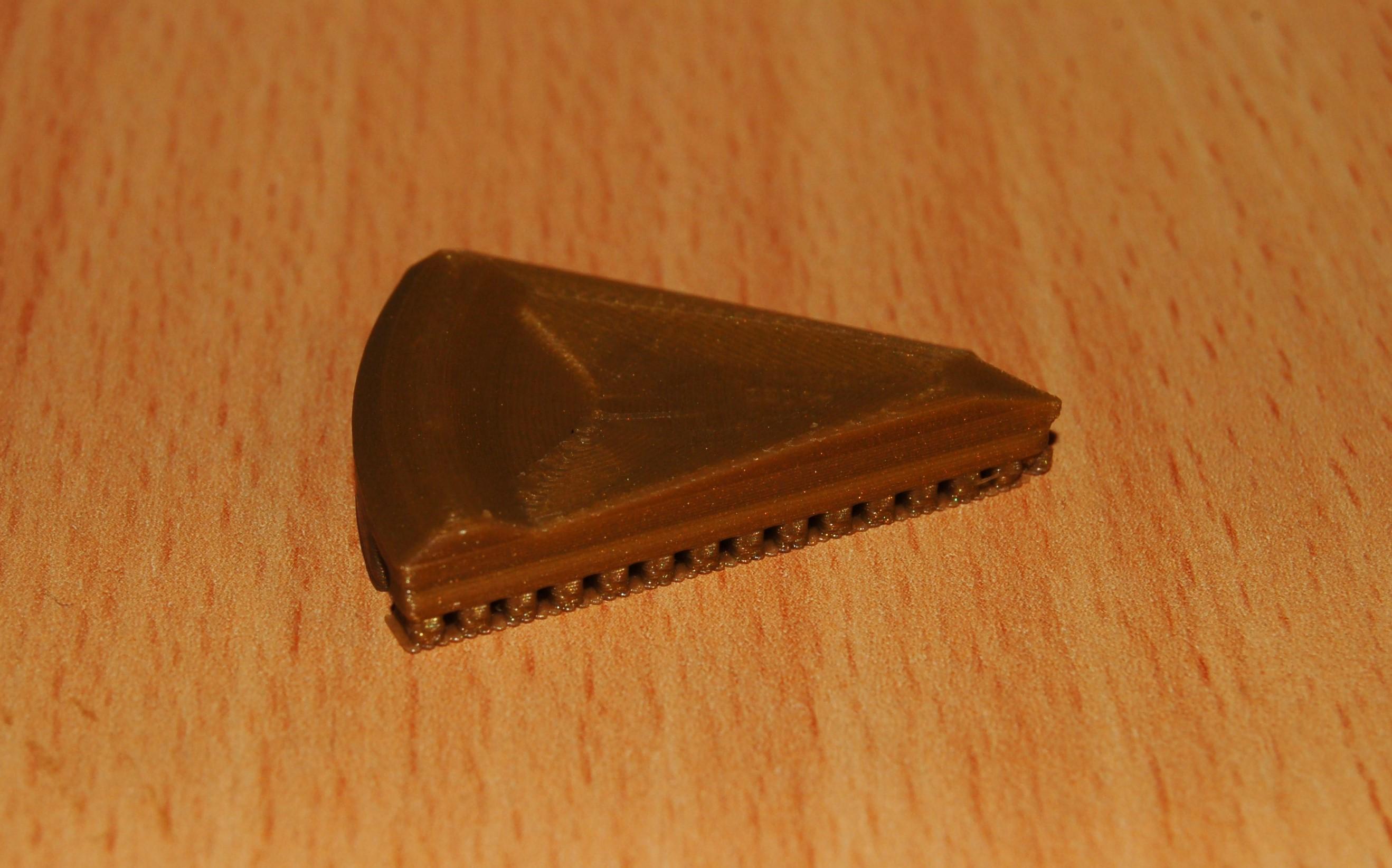
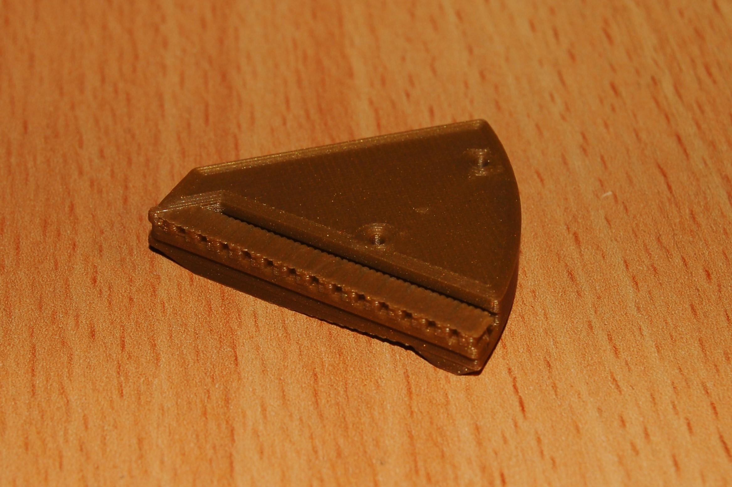
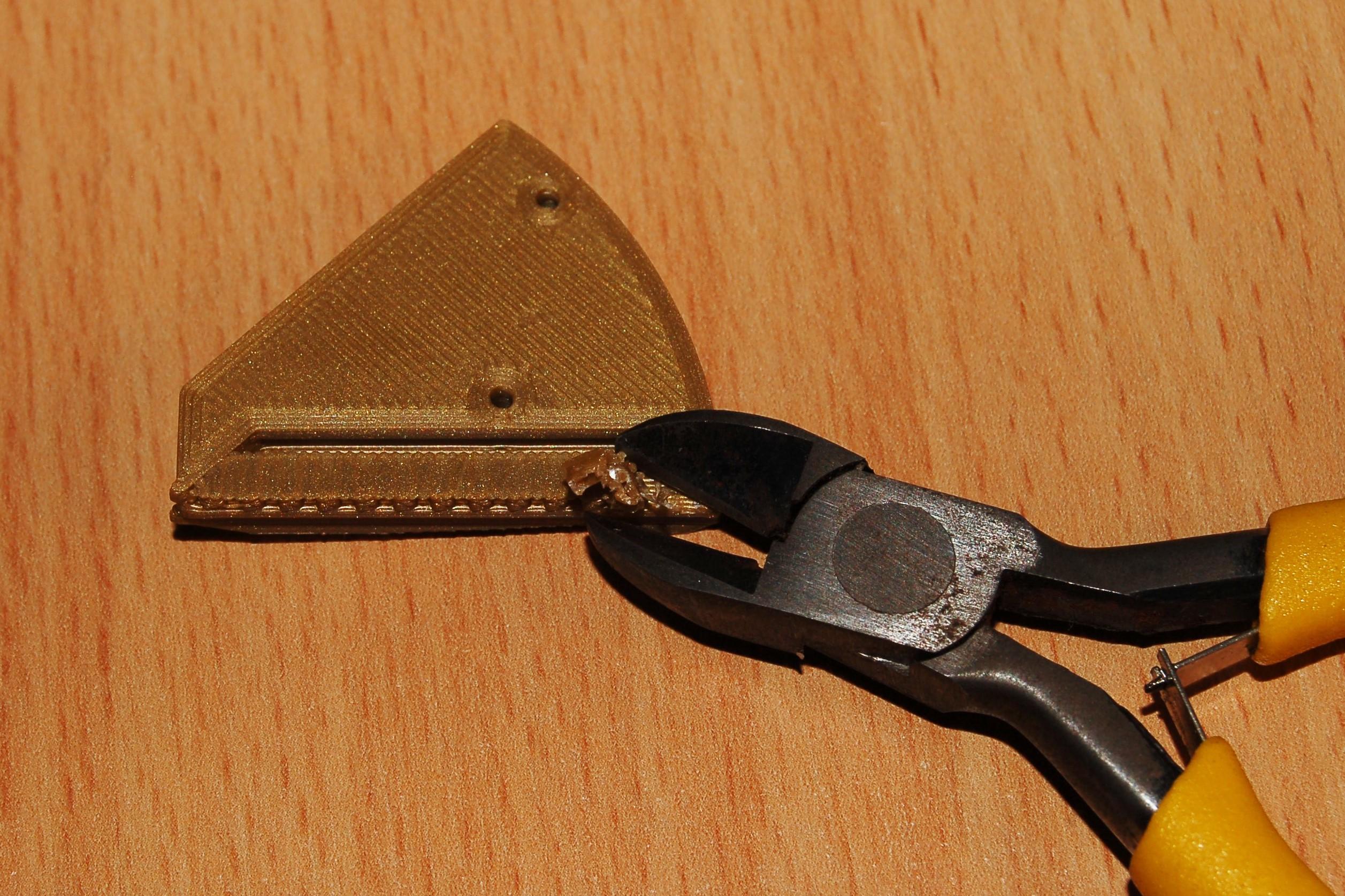
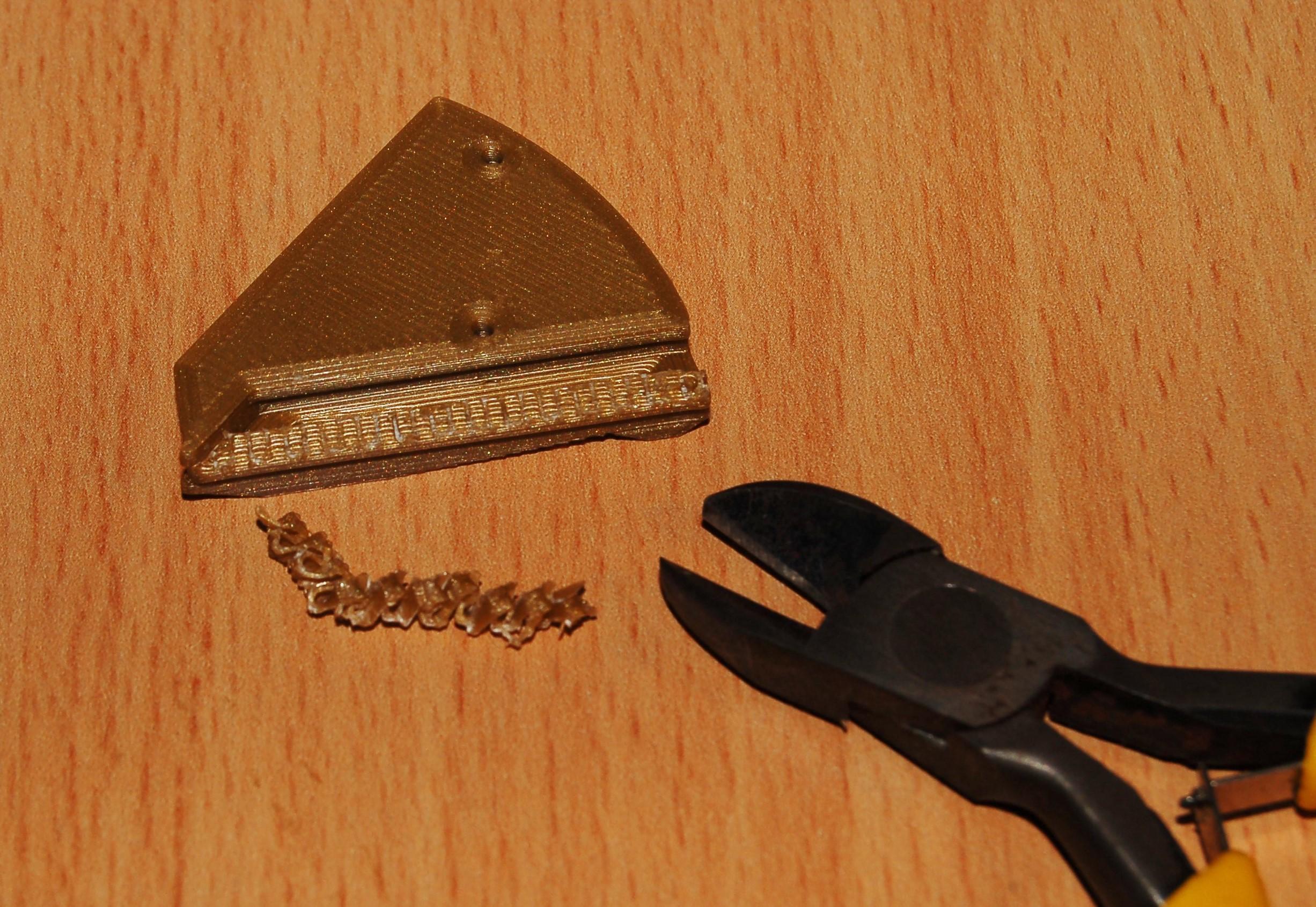
(Ignore this step if you do not want to print any of the Aperture style boxes)
There are two mechanical features on the 12 leaf aperture box which need to be printed accurately, namely the screw attachment holes and the dovetail joints.
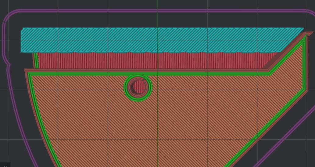
The dovetail joints require support material on the overhanging area, although it is only required on the outside section (see pictures) since the inner section can be bridged easily and filling the dovetail with support material will make cleanup much more difficult.
Dovetail Tuning
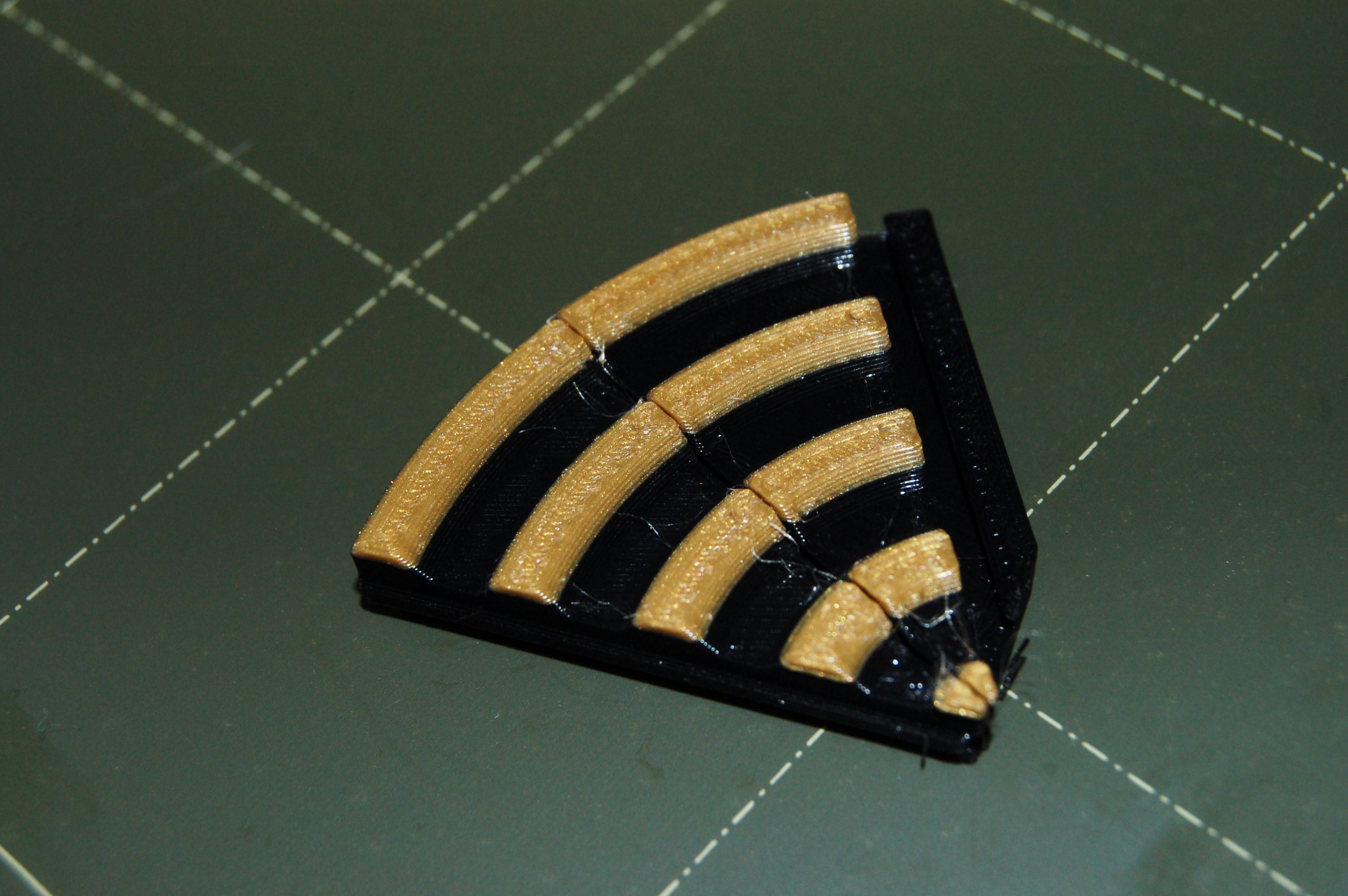
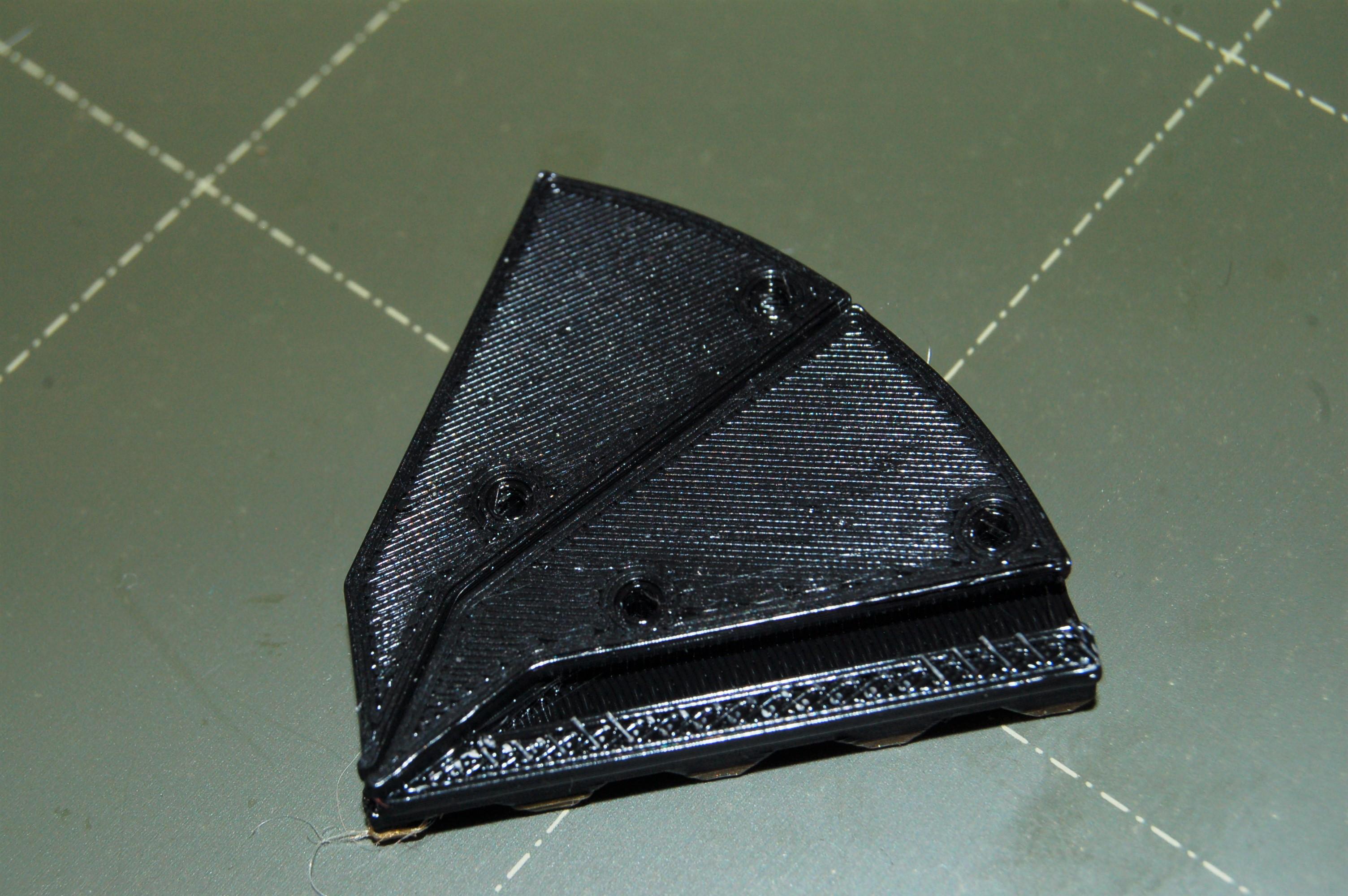
(Ignore this step if you do not want to print any of the Aperture style boxes)
For the mechanism to work well, the dovetails need to move freely with little friction. A simple test is to to print off two doors and slide the dovetails together. Ideally the dovetails should slide by just pushing with one finger but there is usually a bit of friction at first; it may help to work in the joint a little or use a little silicon lubricant
I have designed the dovetails so that they should work fine with typical settings at 0.2mm layer resolution (at default scale). The printed example shown used standard 0.2mm QUALITY settings in Prusa Slicer on the Prusa Mini, and they worked perfectly.
If they are too tight you will need to do some tuning using 'Contour compensation' or 'XY compensation' in your slicer to move the contours inwards. Use print settings to improve the dimensional accuracy if you are having trouble e.g. turn down accelleration and/or print speed; also check your printer belt tensions. Make sure there are no print defects e.g. blobbing, zits. Elephants foot is particularly important to avoid (there are some chamfers on the bottom of the doors to help).
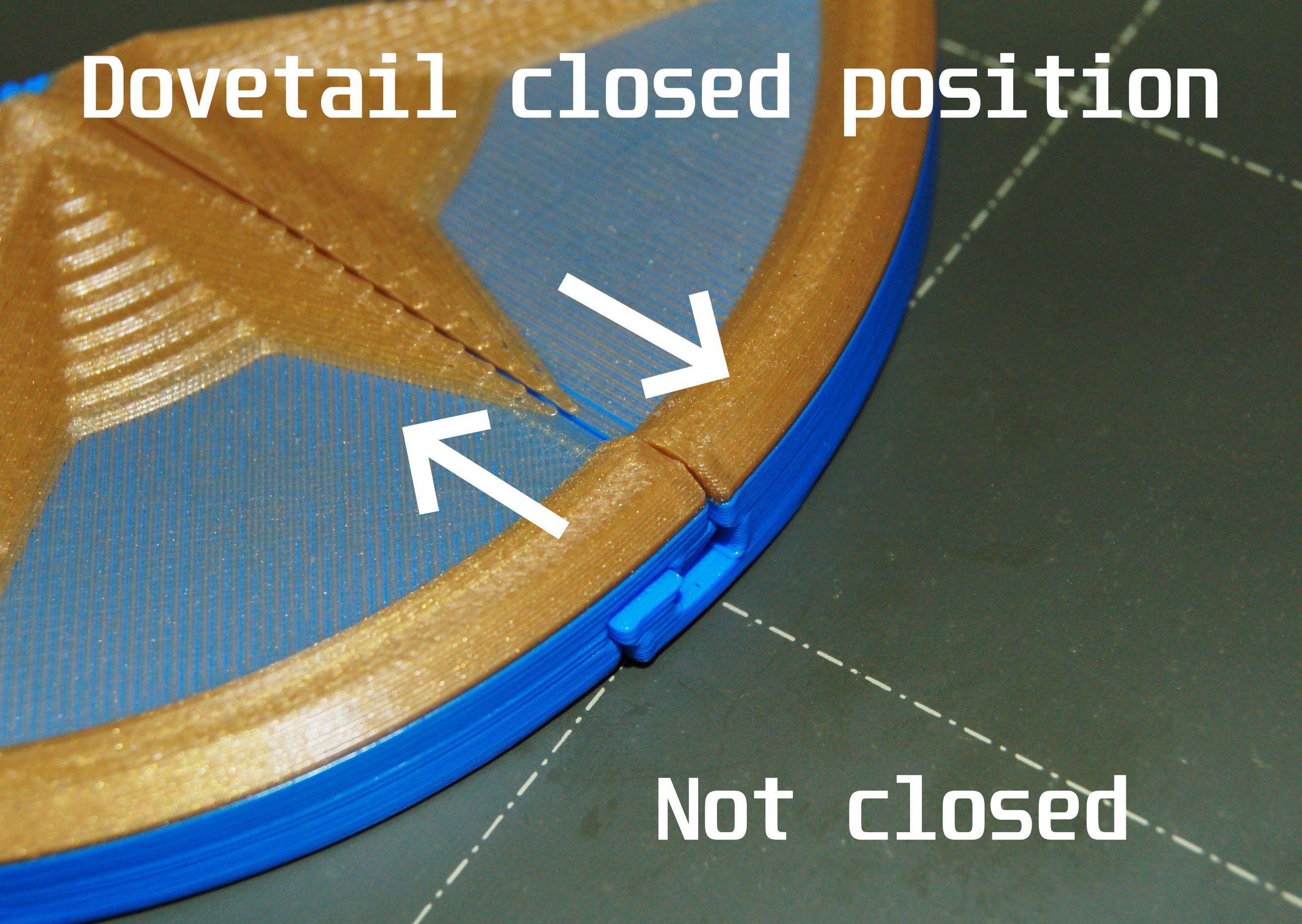
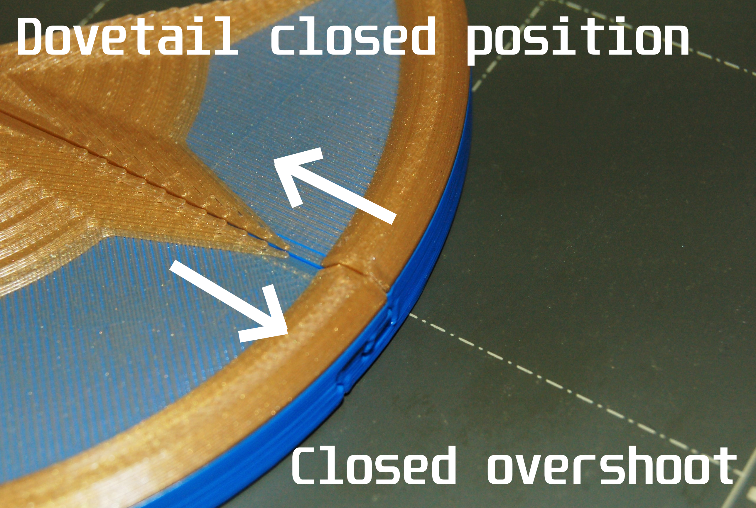
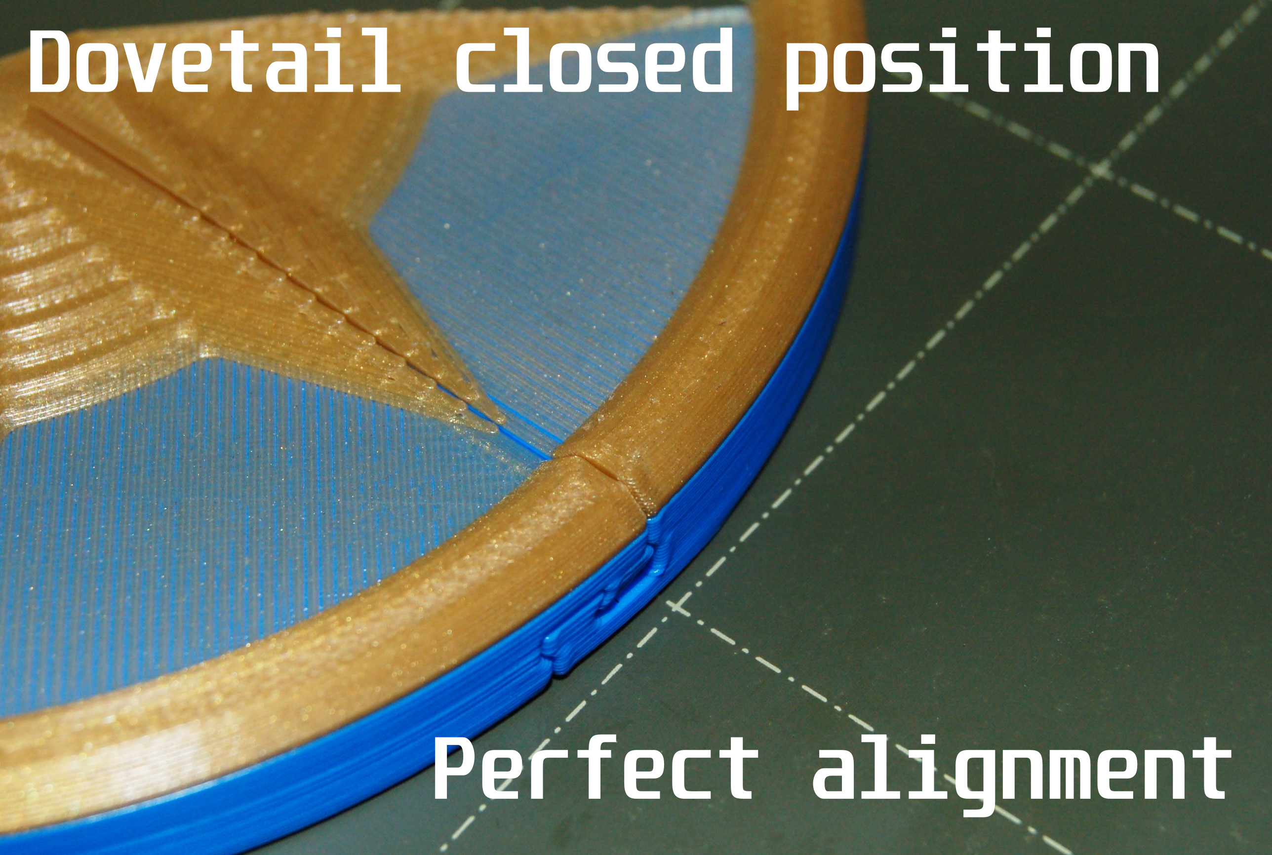
The dimensional accuracy of the dovetails have another impact on the box, namely what position the doors line up at when the box is closed. For a nice box assembly, the doors should produce a neat circle when fully closed.
Due to the shape of the dovetails, they are very sensitive to dimensional error e.g. an 0.1mm contour error will produce approx an 0.4mm positional error when the box is closed. This does not sound like much, but it is quite noticable when the pattern is misaligned when the box is closed.
If the the contours are too far outwards, the dovetail will not slide in enough and the box will not close fully. If the printing contours are too far inwards, the dovetails will slide too far and overshoot the aligned position when fully closed (see pictures). In reality I have found a little bit of overshoot ideal, since it helps the mechanism close fully and this is designed into the parts, but you can experiment and tune it yourself if you wish.
Overshoot is less of an issue with the 'Aperture Iris Box' model as other parts of the mechanism help things line up.
One issue that may arise is that when you scale the parts up e.g. 150%, the contours need to be retuned to get a neat assembly. I have a feeling the overshoot I designed into the standard scale parts will become significantly more noticable, and unable to tune out by pushing out the contours without the dovetails getting too tight. If you are having issues with this let me know and I will make new doors to account for this.
Hole Tuning
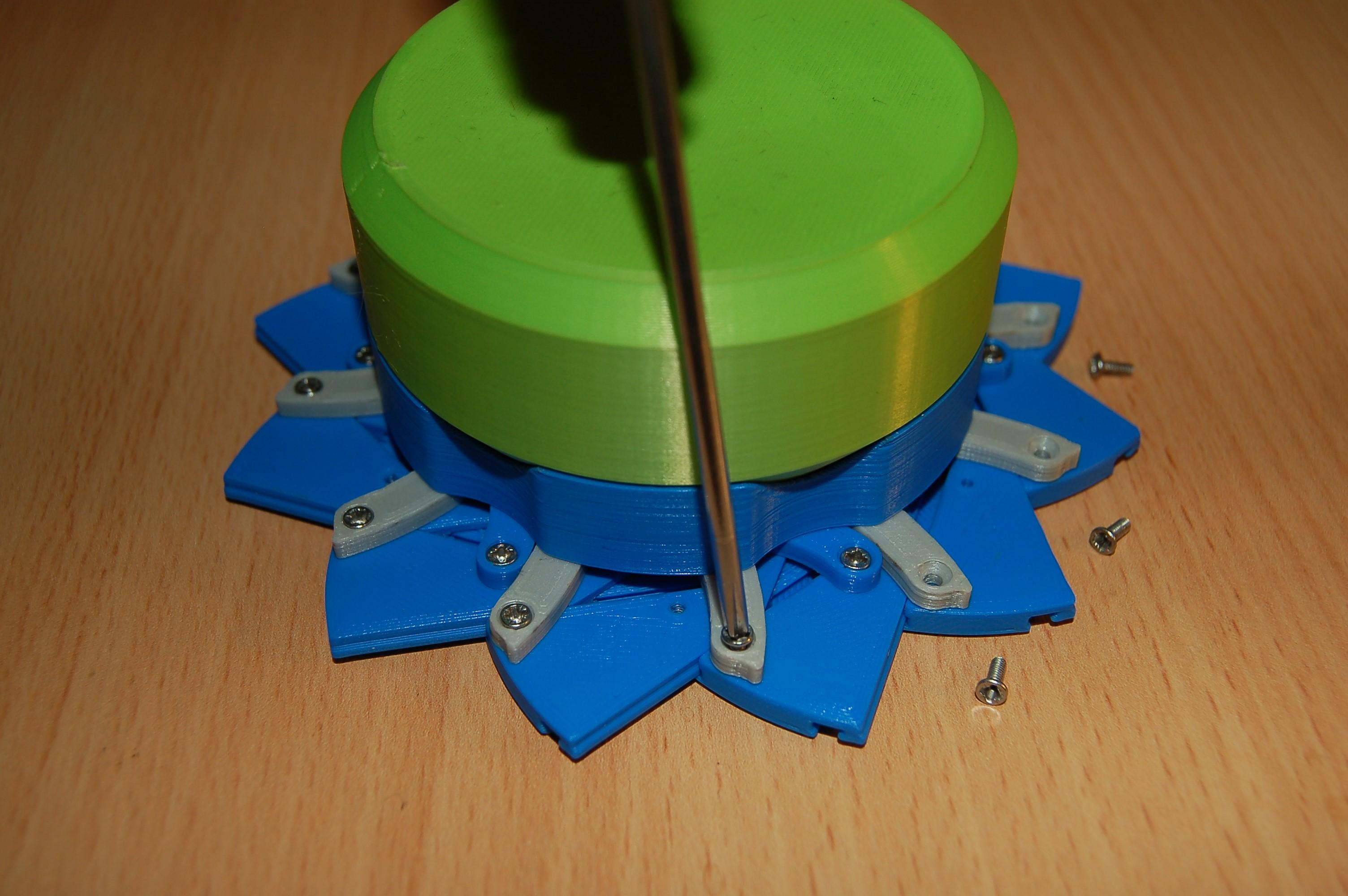
Most of the boxes require screws to assemble, M2x6mm countersunk screws at default scale. It is worth doing a test print to make sure they fit tightly in the top door parts (and by extension other parts including the container), but also are free to rotate in the links and the head is flush with the part surface.
In general there should be no problems with the screw fitment but it is possible with different material/temperature/slicer/printer combinations that the holes may be too tight or loose.
If they do not fit correctly, you can either scale the model, or my preferred method is to use 'Hole contour compensation' or 'Hole XY compensation'. Try not to use generic all contour expansion as this can affect the dimensional accuracy of the assembly. I recommend Idea Maker since that is a free slicer which has both outer contour and hole contour compensation which can be tuned separately.
To tune the aperture boxes hole size with a slicer with no hole contour compensation, you can use a combination of scaling the part to fit the screws and all contour expansion to tune the assembly fit, although this is a more complex approach (or most likely it works as designed with standard print settings) e.g. Prusa Slicer as of writing does not yet include hole compensation.
Multicolour Lid Patterns
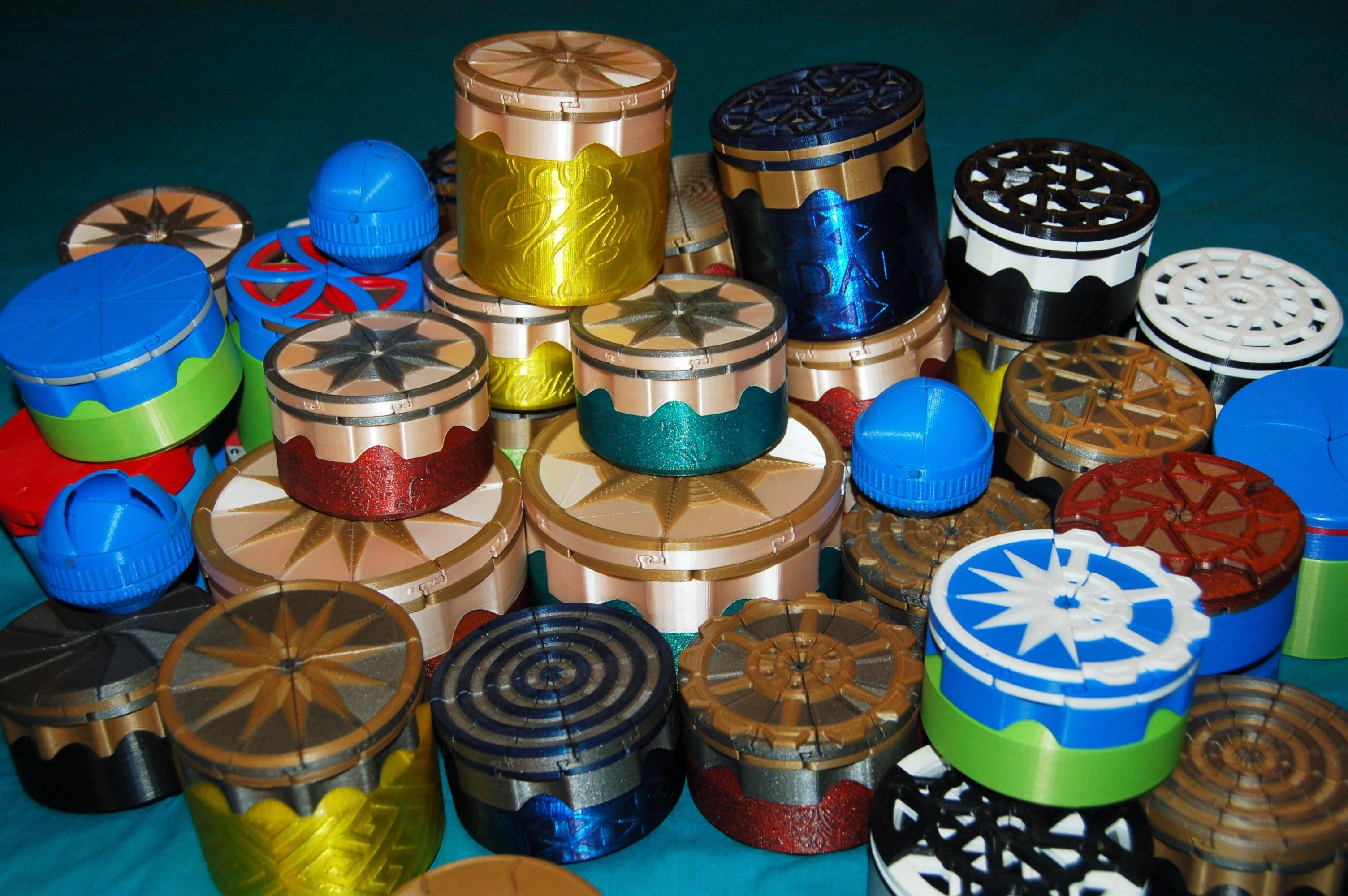
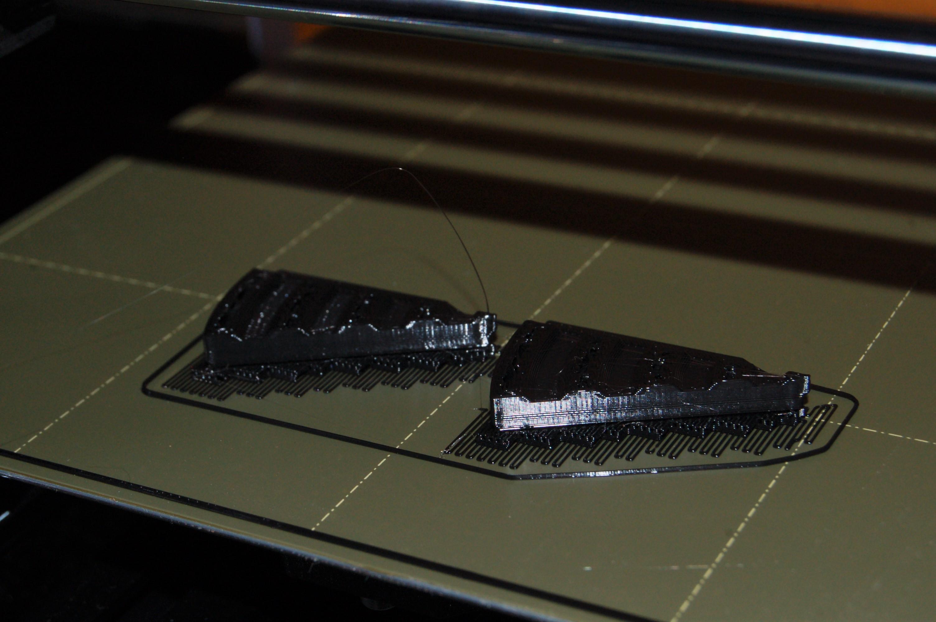
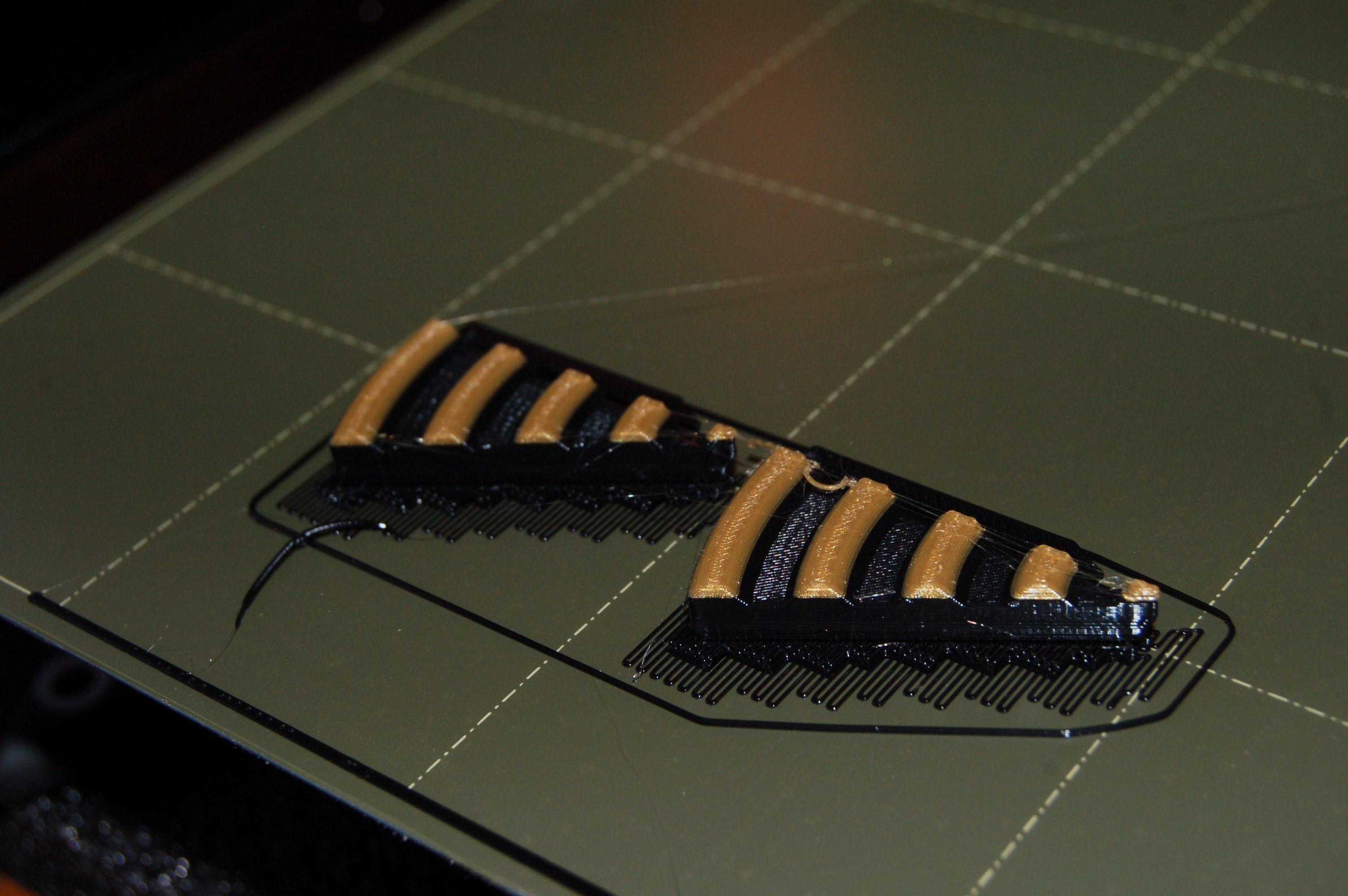
Many box lids can be made multicoloured, either by printing the separate parts in different colours (such as the flower iris boxes) and/or by doing multicolour prints for the top door parts. A multi-material printer is not necessary to produce the multicolour prints, they can be done simply by doing a material swap at the appropriate height; almost all the boxes pictured were printed on my upgraded single nozzle Anet A6.
- For most printers, the command to swap the filament is M600 (Marlin) sent at the appropriate height in the print and I recommend this as the simplest method (or built in material changes in the slicer as with Prusa Slicer).
- For some of the boxes, I have broken down the lid pattern into separate parts for those who have a multi-material printer.
-
If you cannot pause the print to change the filament for whatever reason, there is also the multi-pass printing technique. Here the different parts are printed with different Gcode files e.g. the first Gcode file prints the base, the material is swapped out to a different colour and then the pattern is printed on top in a separate Gcode file. This is a less optimal approach, partly because it is more complex but also because it depends on the repeatability of the printers homing. Unprecise homing can lead to the top pattern being misaligned significantly to the base. I recommend printing all the doors at once if you go for this method, since at least the misalignment is at least symmetrical around the box.
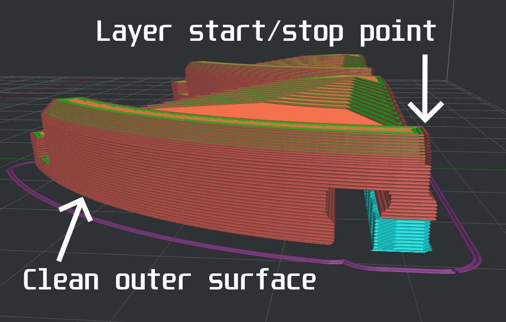
To get a neat box, I also recommend making sure the layer start/stop points are set at sharp corners in the layers to hide them. This is particularly important for the parts visible around the circumference e.g. the outside of the doors or opening collars (these can be particularly tricky to make neat). I also generally print the top pattern with a finer layer resolution than the base for quality e.g. 0.1mm layers when the base is 0.2mm (see picture).
Container Velocity Painting Overview
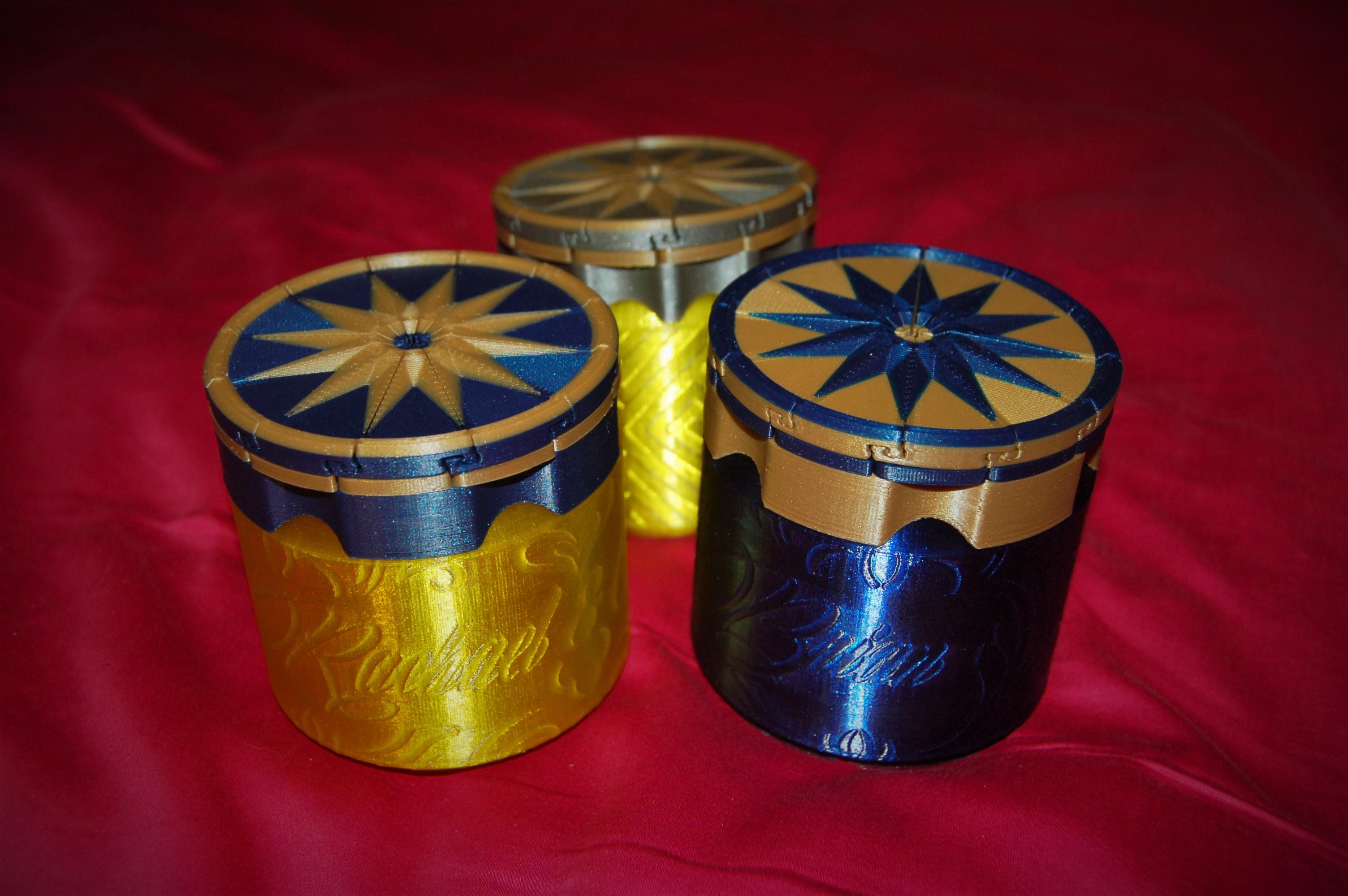
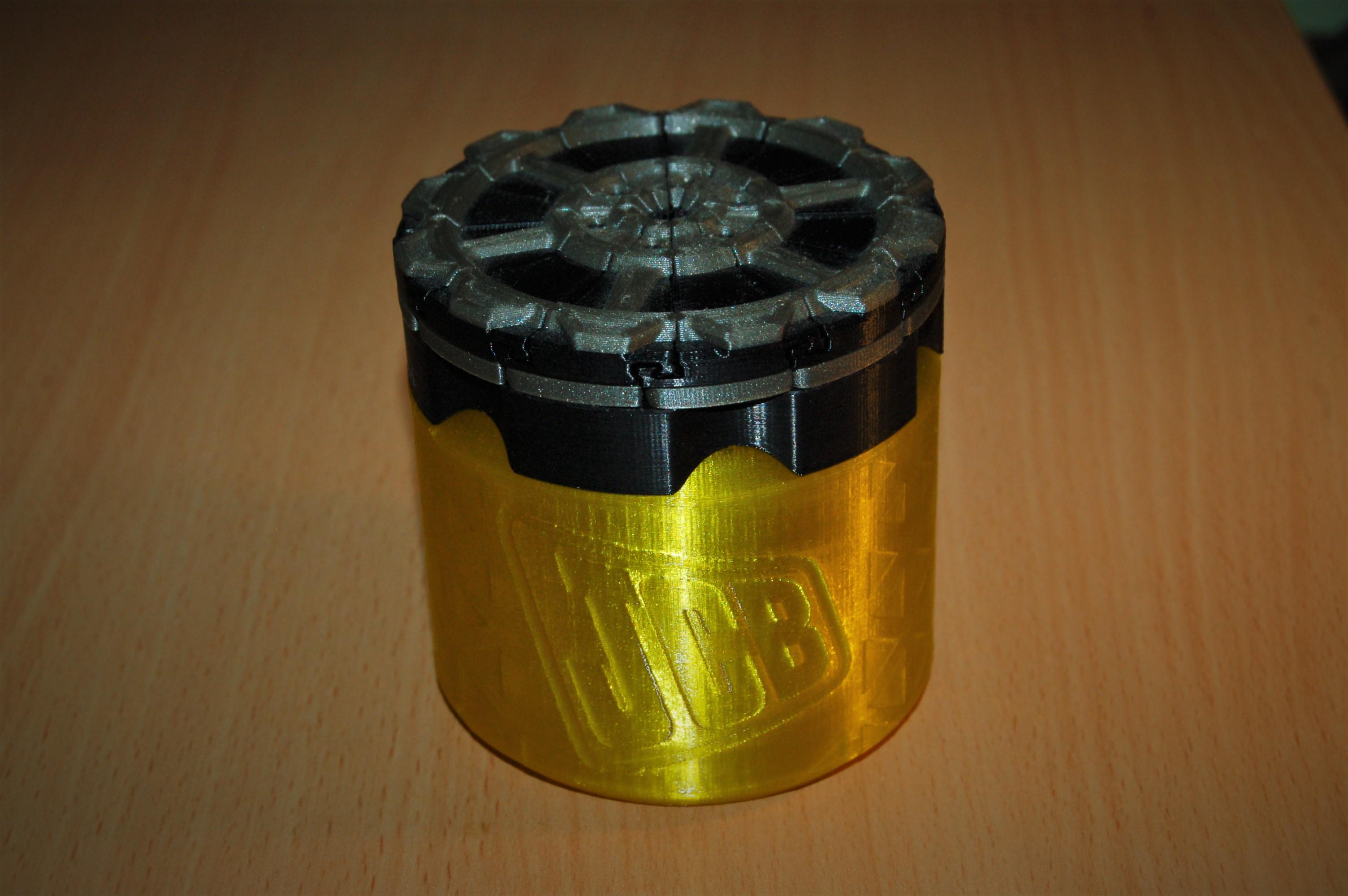
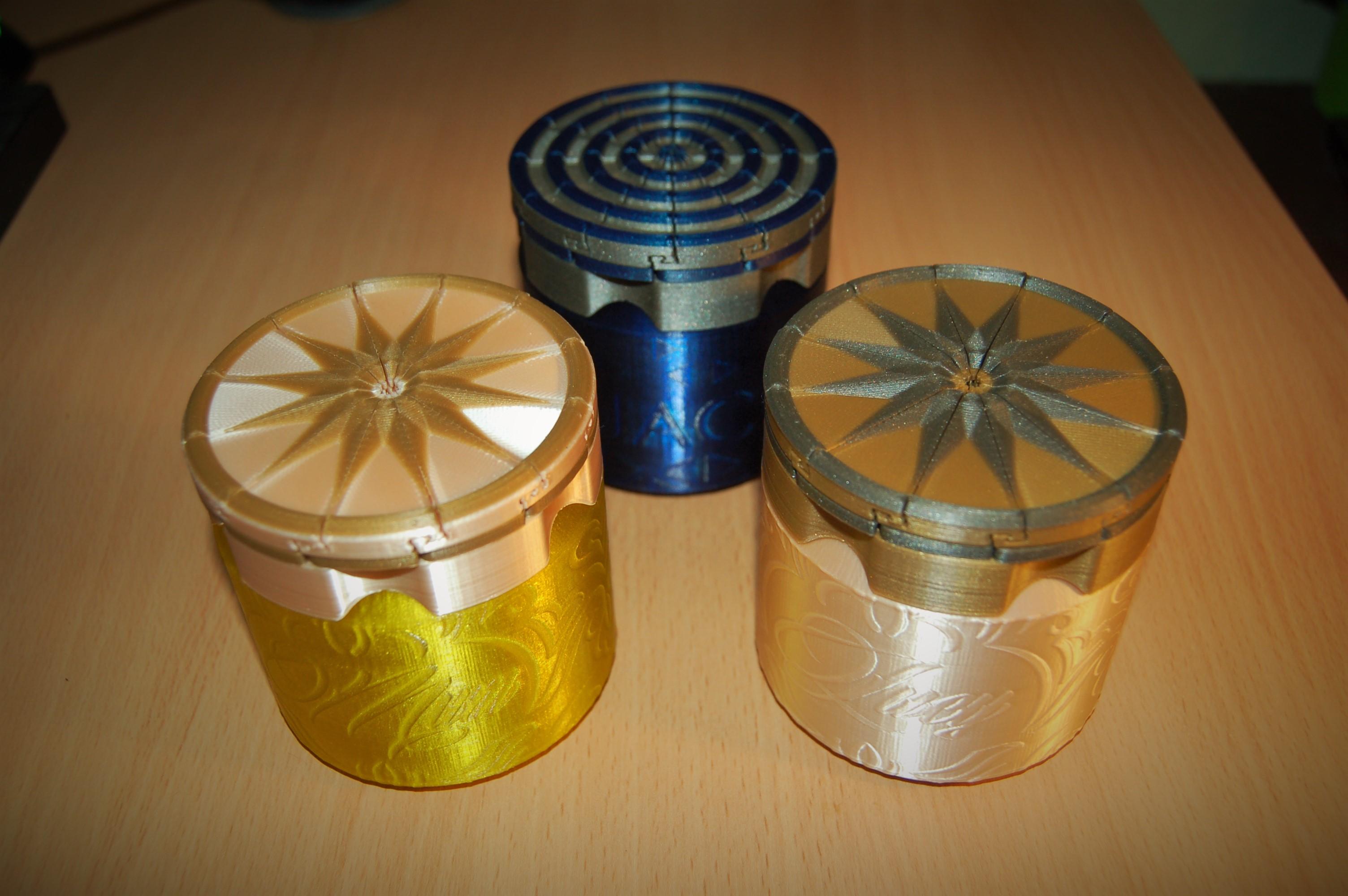
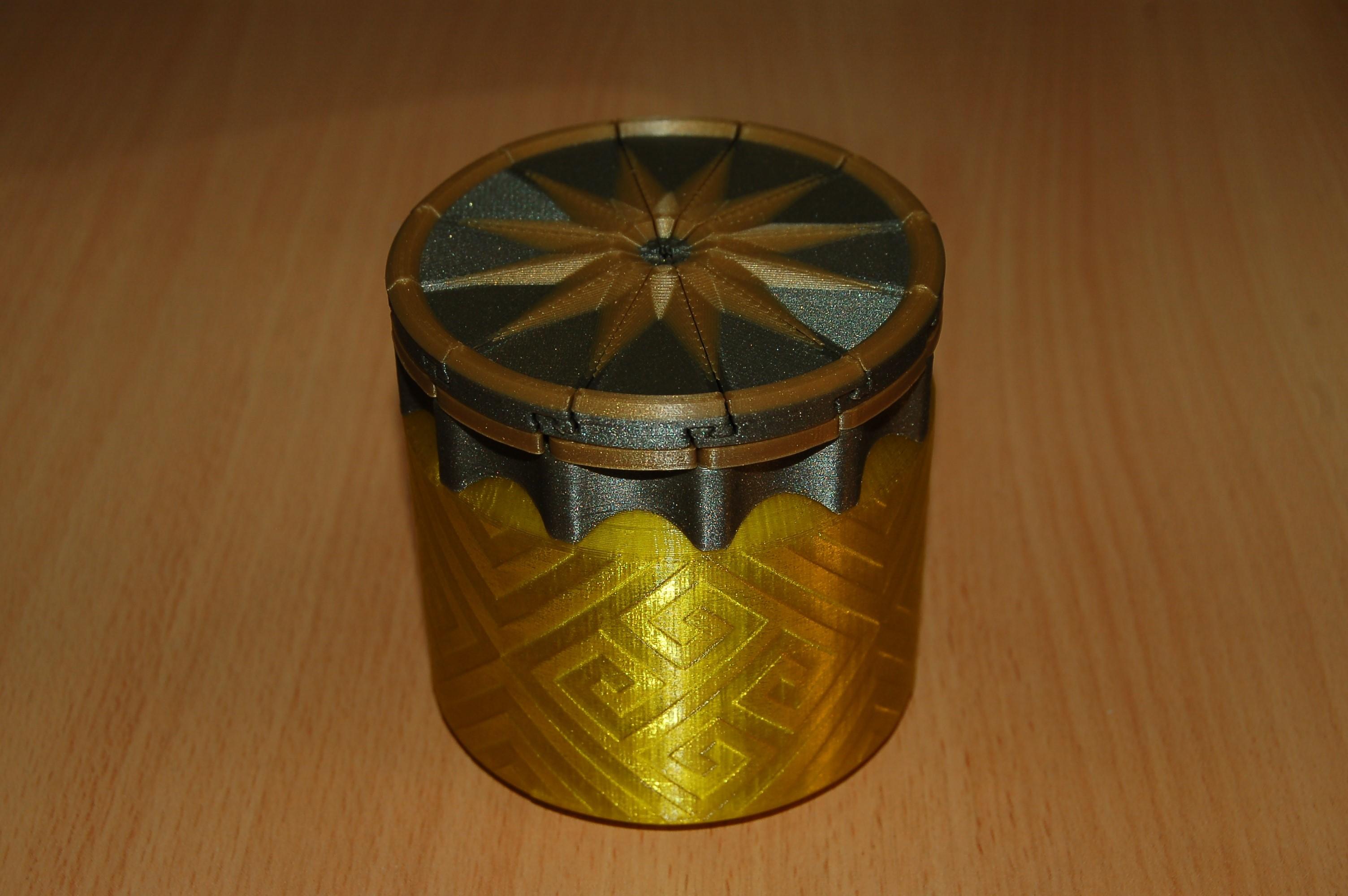
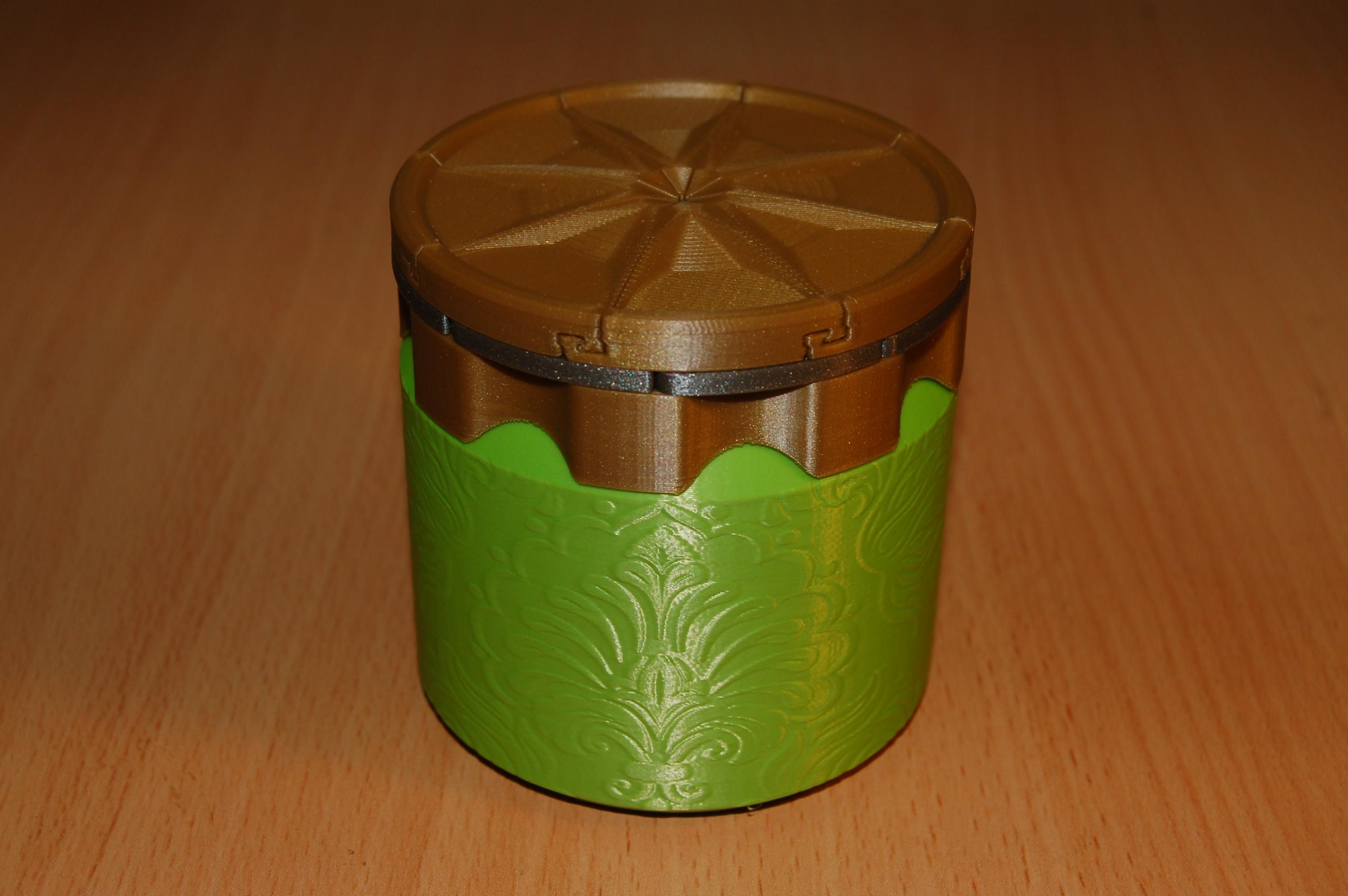
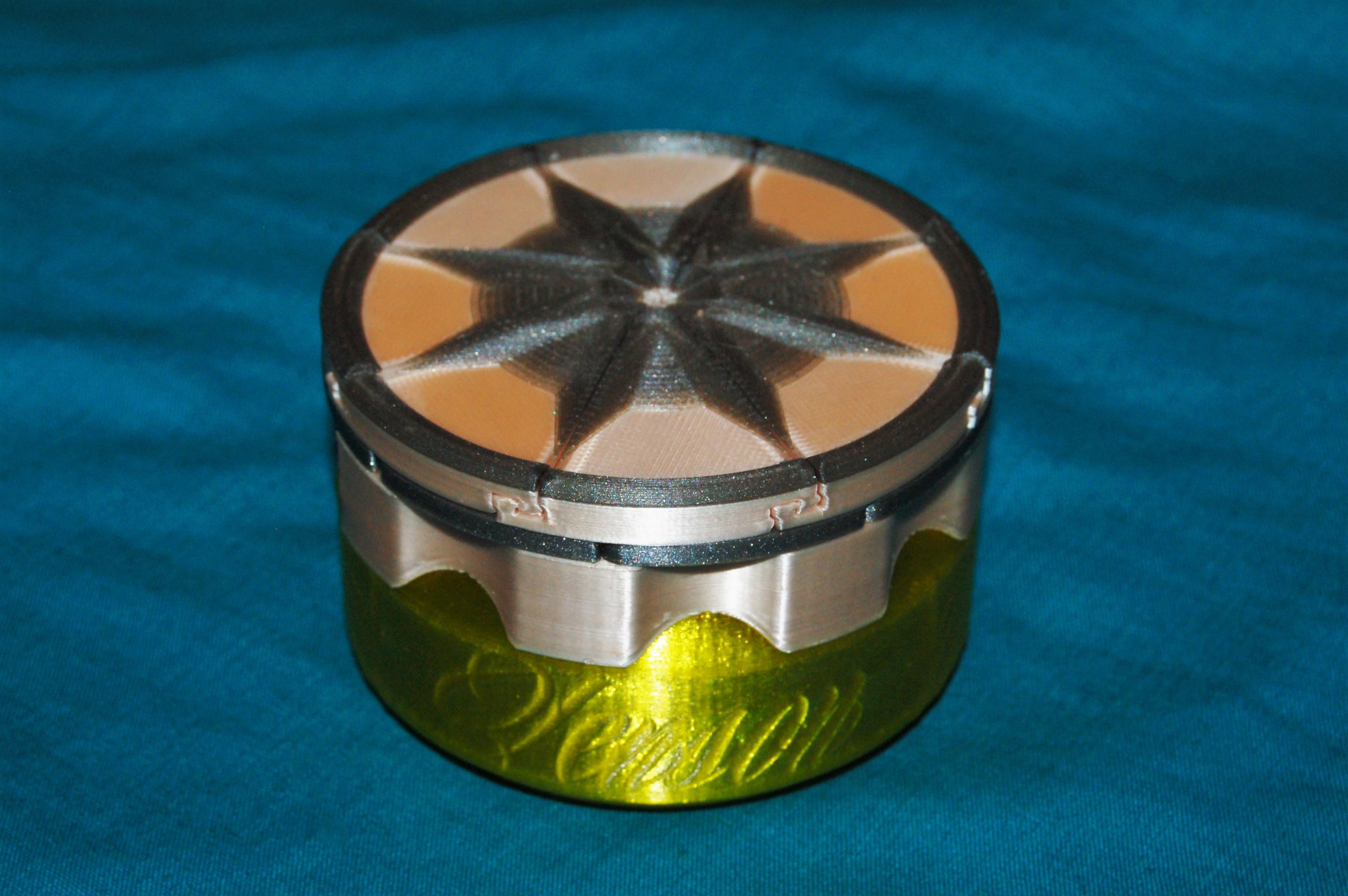
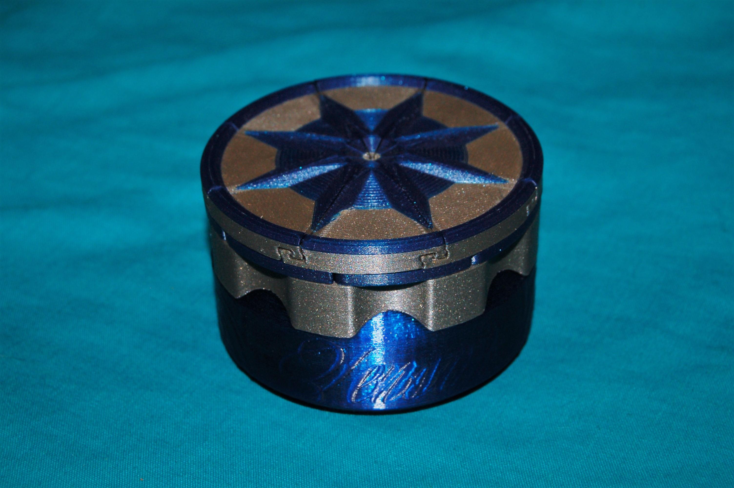
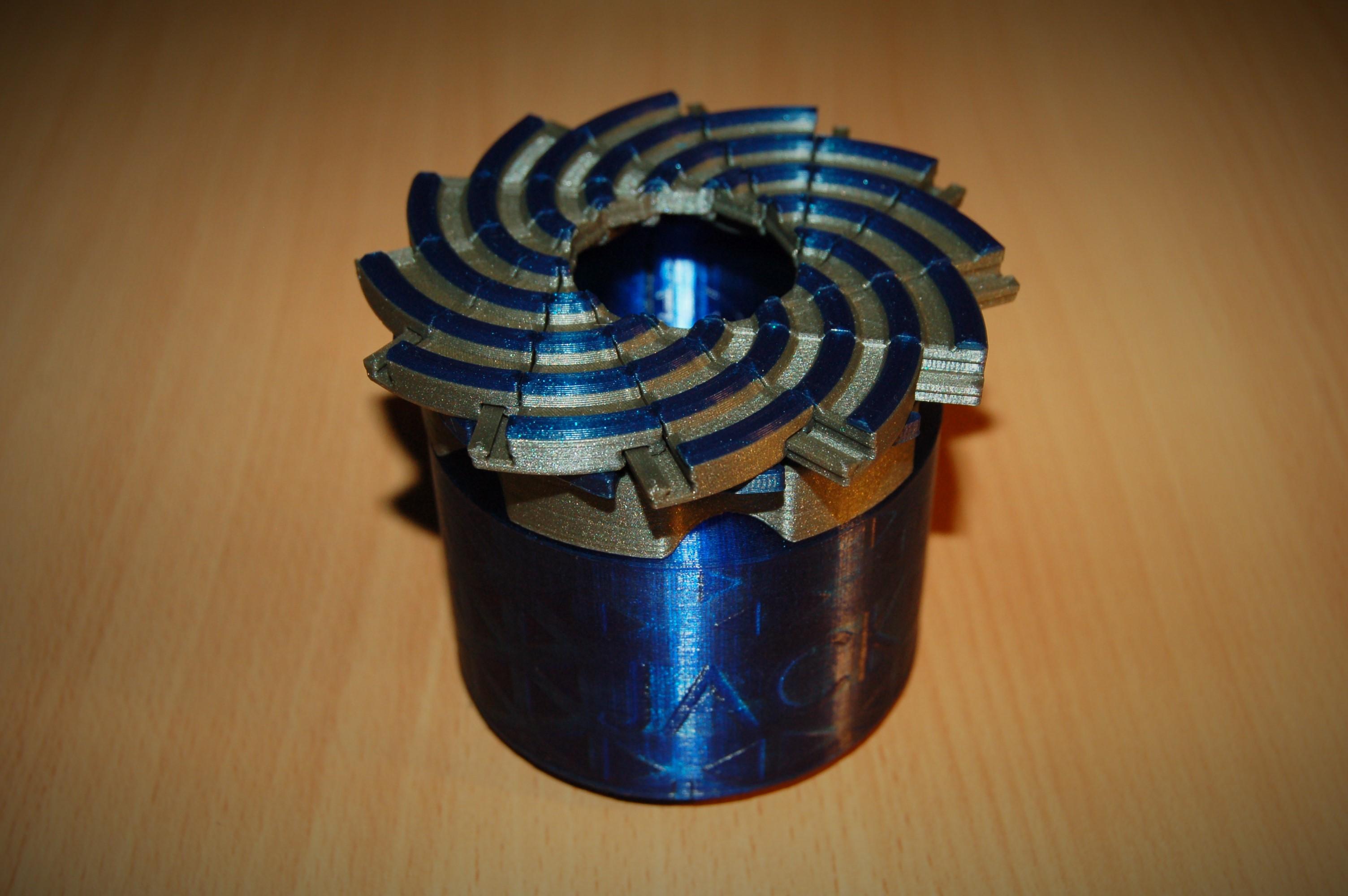
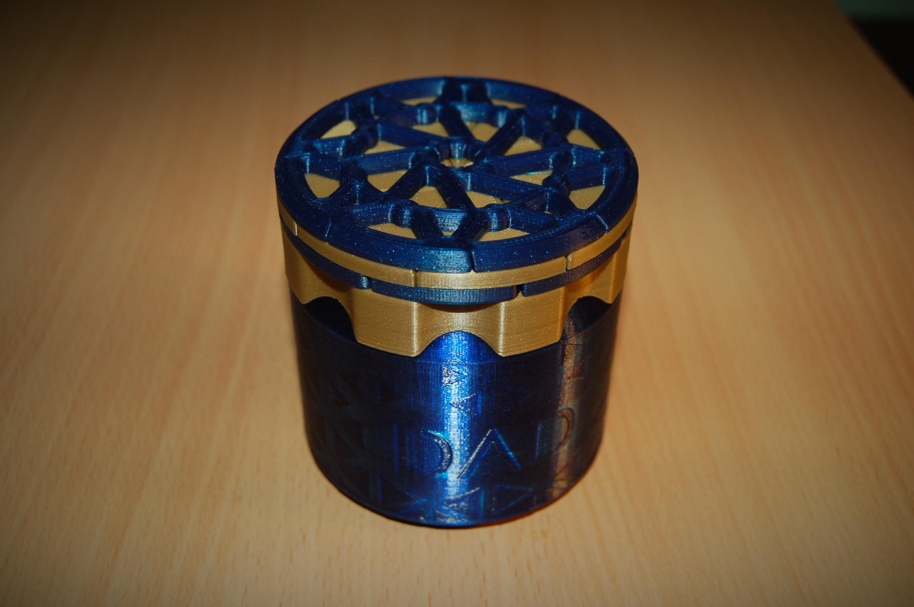
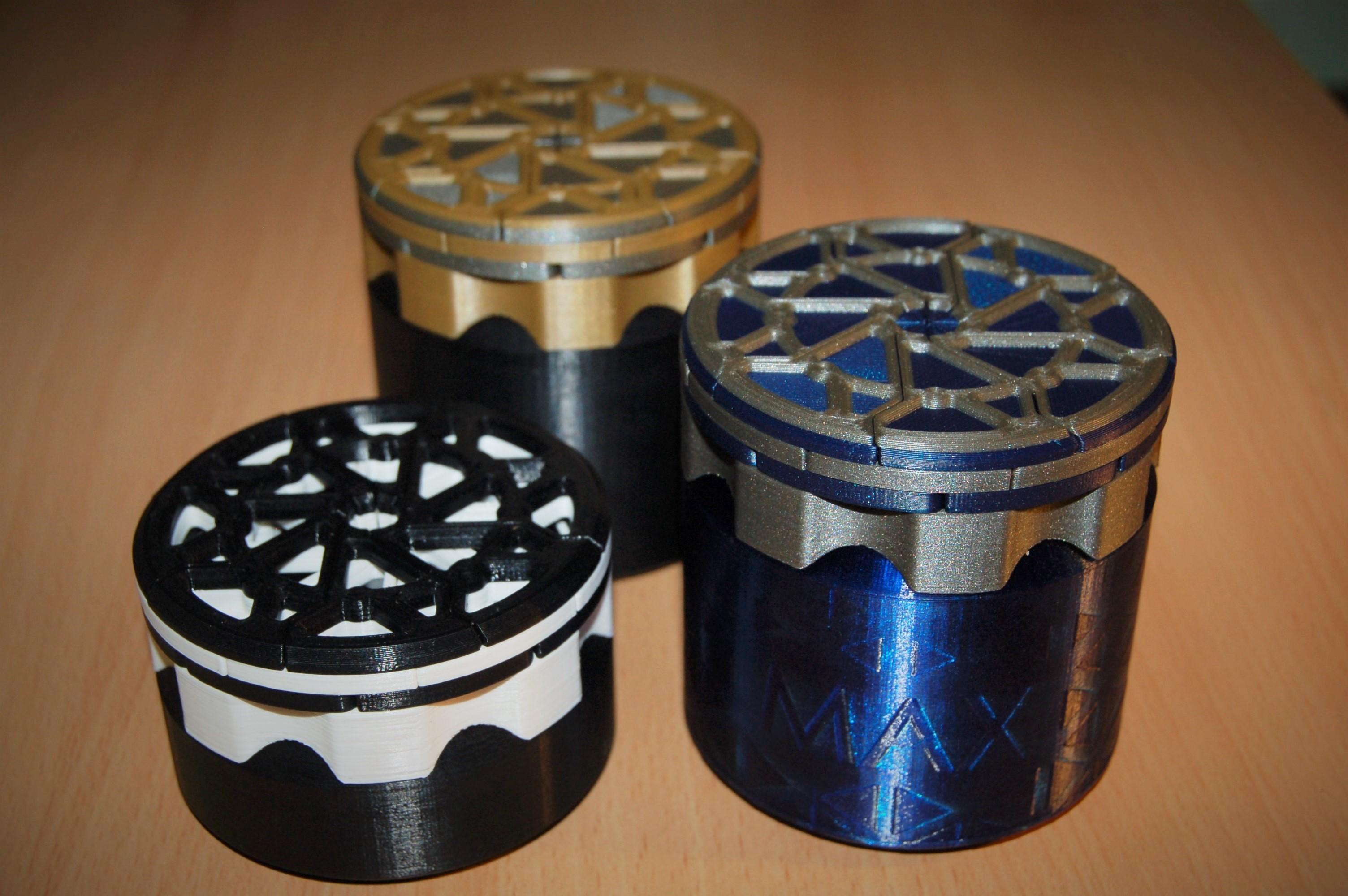
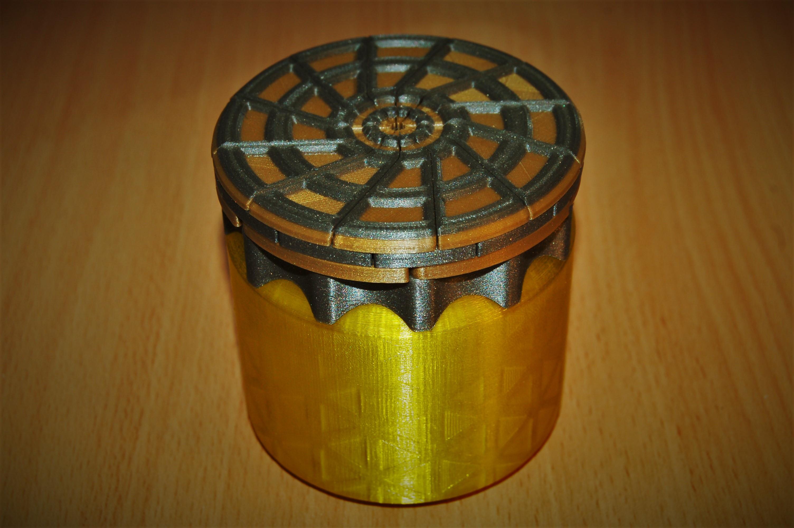
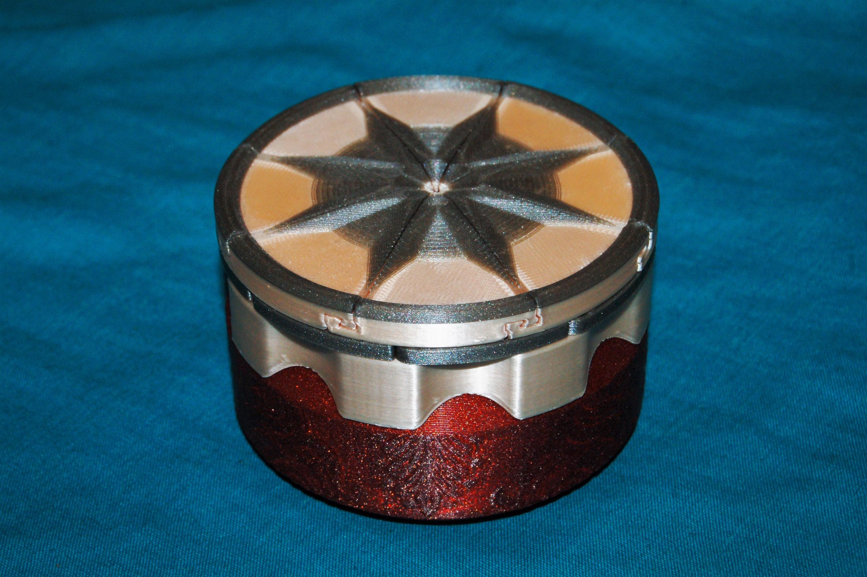
Perhaps one of the most striking and decorative parts of the box, velocity painting really improves the look and is perfectly suited to the cylindrical shape of the containers. It is particularly good for making custom named boxes, which I have made many for friends and family.
The technique works by changing the speed of printing at different points in the print. The speed transition changes the thickness of the extruded material, creating the visible pattern. This works particularly well with transparent materials such as PETG shown in the above examples, producing shiny optical effects.
I use Repetier Host software to add the pattern to the Gcode files. Repetier has some of the common slicers built in e.g. Cura, Prusa Slicer, but any Gcode file can be imported to Repetier and velocity painted.
A slight issue I encountered when first doing velocity painting, is that my Rasberry Pi I used to send the Gcode files, could not send all the data across (due to the continuous rapid changes in print speed) to the printer fast enough (probably because I was conected to a Pi Zero through an adapter). This lead to the printer stalling at points and ruining the pattern. I solved the issue by printing the file directly form an SD card on the printer.
The Idea Maker slicer has recently added a texturing feature which works in a similar fashion to velocity painting, except it produces the pattern by physically texturing the surface, not changing the print speed. I have yet to see how well this could work compared to velocity painting, but at the very least it could speed up printing times siginificantly.
Velocity Painting Settings
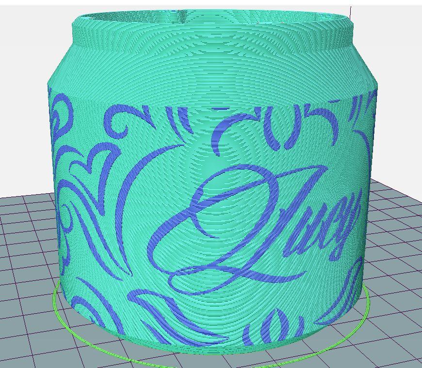
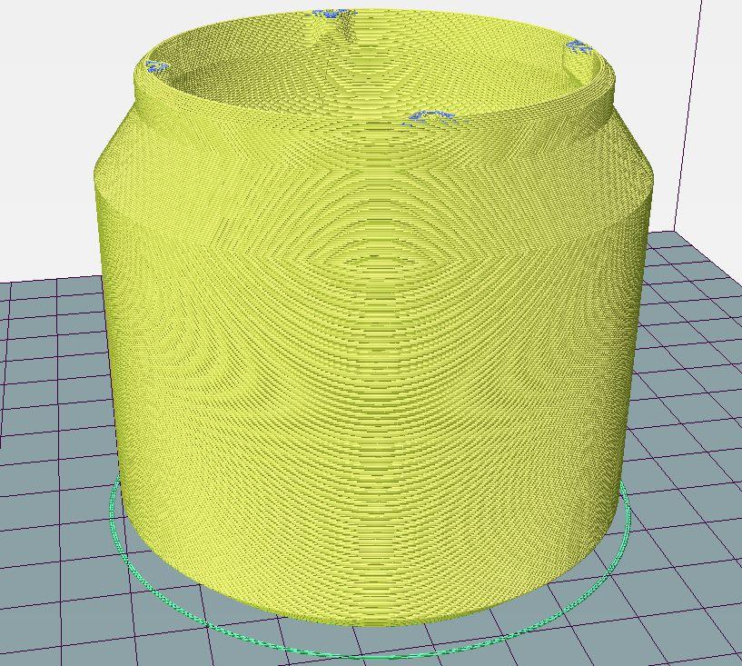
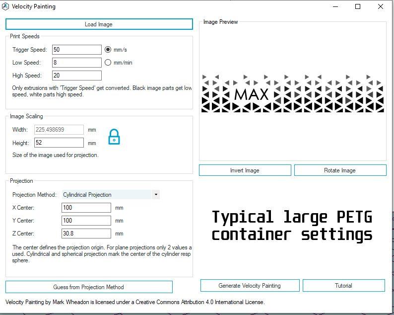
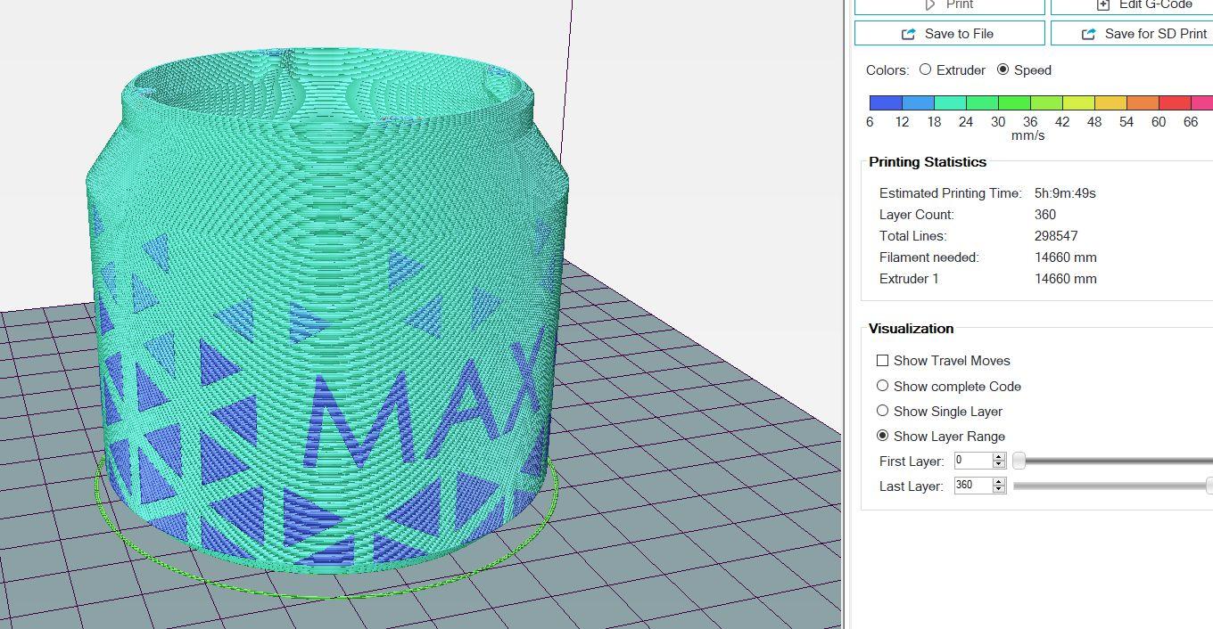
Import the base Gcode into Repetier or use one of the in built slicers e.g. Prusa Slicer.
From the menu bar select Tools --> Velocity Painting.
The velocity painting dialog will open. There is a small description for the settings which is fairly self explanatory but I will briefly go through how it works:
- Load Image: Select the image you want to use for velocity painting.
- Trigger speed: Only the parts of the Gcode with this print speed will be affected by the velocity painting. This is particularly useful for making sure only the outside perimeters are affected, otherwise the speed of everything would change including the infill which would waste a lot of time. Set this to the outer perimeter print speed of the Gcode file.
- Low speed: The low speed the velocity painting will apply to the darkest areas of the pattern.
- High speed: The high speed the velocity painting will apply to the lightest areas of the pattern.
- Image Scaling: Sets the size of the pattern on the part where appropriate e.g. 52mm tall for the cylindrical section of the containers. (For cylindrical projection the width is not necessary since it projects the image outwards 360 degrees in a cylinder)
- Projection method: The method of projecting the image through the part, in this case it is cylindrical.
- X/Y/Z Centre: The central position the image is projected from. In this case the X/Y centre position is in the centre of the container. Use the central coordinates of the container when you sliced it. I usually let Repetier place the object automatically in the centre of the bed which is X100, Y100 (or do trial and error to get it central). Z Centre is how far off the bed the centre of the image is, for most of the large containers, as with the example, it is 30.8mm.
- Invert Image: Inverts the dark and light areas of the image, swapping high/low speeds. Try to make it as light as possible (minimum dark areas) to make the print as fast as possible.
Once you have the correct settings, select 'Generate Velocity Painting' to generate the preview (make sure you have selected the 'Speed' option for the Gcode preview to show the pattern). Changes to the settings can be made by simply going back and altering them and the preview will update accordingly.
I have included an image of the settings I use to do PETG containers. To get a good pattern you want a big change in print speed e.g. 2x speed change. I found that 8-20mm/s worked best for PETG. This is quite slow but I found at higher speeds it would introduce air bubbles which ruins the shiny effect with transparent filaments. I also found that using a single width extrusion fill at 30mm/s in the middle of the container walls (rather than two inner perimeters it would normally do) produced the best shiny results. Feel free to experiment with different settings and materials yourself.
It is worth doing test prints to tune the VP settings. I have attached a couple of files, 'Velocity painting test.stl' (intended for vase mode printing) to see what your pattern looks like and 'Container wall test 2' which is a slice of the container, scaled down slightly to test what the final print will look like.
Velocity Painting Images
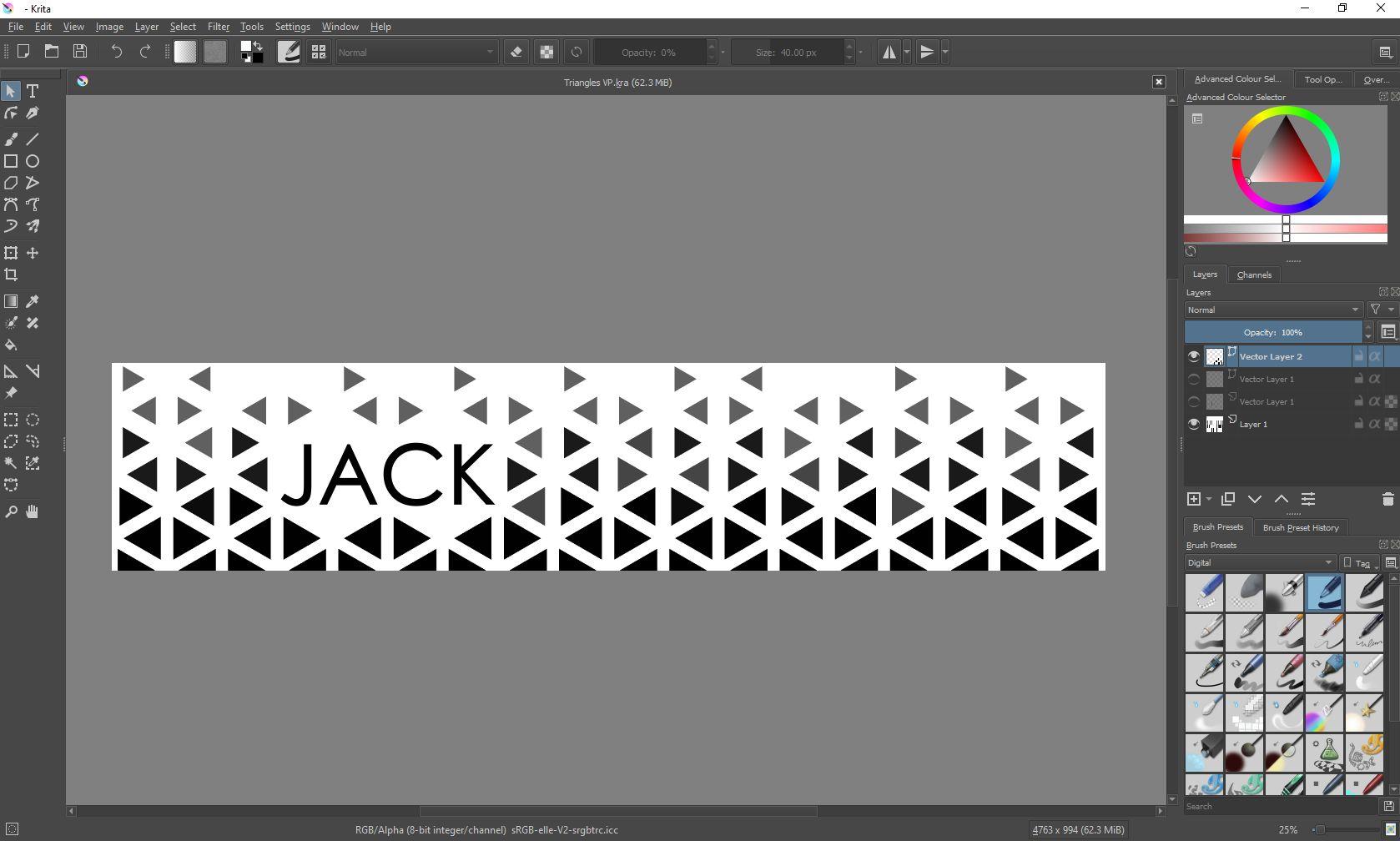

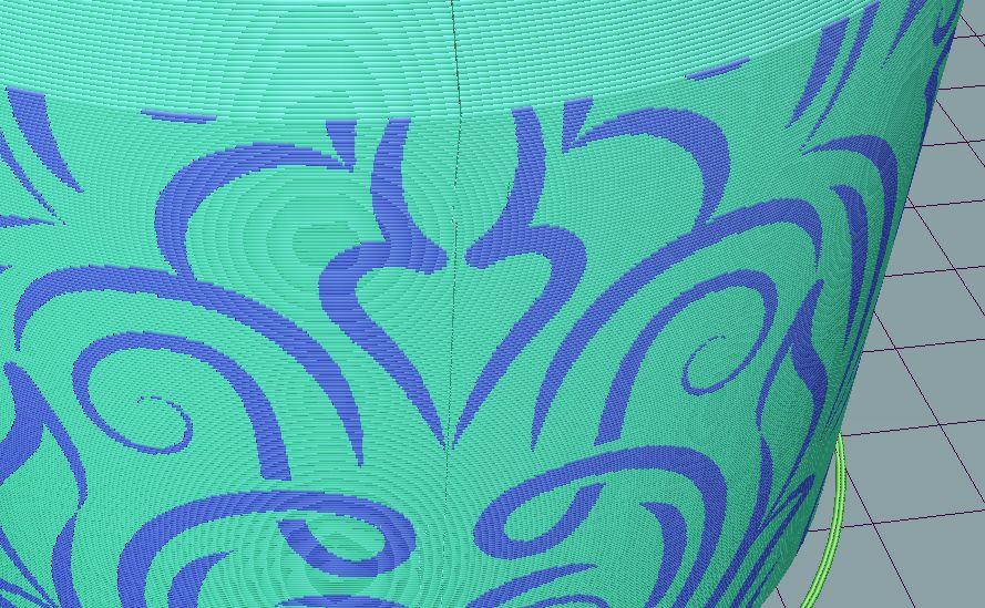
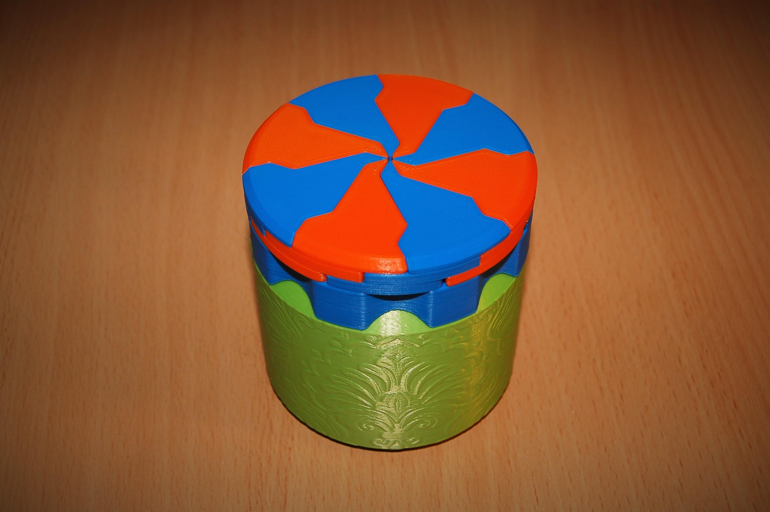
Now you know how to do velocity painting, we just need some images to do it with. I get free pattern images from Freepik. To get a pattern which wraps around container without an obvious edge, I look for repeating pattern type images. Often these patterns have mirror lines in them, so I cut off the edges of the image on these mirror lines. That way the edges of the pattern match up seamlessly. I also try to make the 'seam' of the layer start/stop points line up with a mirror line of the pattern to make it less obvious. In Repetier host, the VP pattern projection starts and finishes on the left hand side (or the west direction), so it is best to line this up with the 'seam' of the print layer lines.
To make sure the pattern appears correctly on the container, the right aspect ratio for the image is needed. This is the ratio of the height and perimeter of the outside cylindrical section of the container. The approximate aspect ratios for the four newest iris box designs (Aperture Iris Box, 12 Leaf Aperture Iris Box, Octo Iris Box, and Dodeca Iris Box) are 1:5 for the large container and 2:25 for the short container.
The correct aspect ratio can be calculated for any size container by measuring the height and circumference of the area you want to cover. The height can be calculated by checking the number of layers in the slicer e.g. 200 layers at 0.2mm is 40mm in height. The diameter of all my iris boxes at standard scale are identical, 80mm, giving a circumference of approx 251mm (diameter*Pi). This ratio of height to circumference will give the aspect ratio you need.
To make the pattern stand out, big changes in speed as the print head is moving and therefore light and dark areas are required. Lines parallel with print layers also do not always show up well, since there is no changes in speed while printing to produce a visible edge. Velocity painting also does not work as well with grayscale images, particularly with transparent materials, if the image doesn't have sharp edges it does not show up well. Many patterns already have sharp edges, although they may need to be edited to get it into a solid black/white form. I personally use Krita which is a powerful and free image editing/painting program.
It is important to export the images with a solid background, otherwise the velocity painting program interperates the transparency as solid black colour.
Unfortunately I am unable to share the altered patterns I made for my boxes, since they were downloaded under the terms of the free Freepik licence (no redistribution).
The floral patterns were remixed from a design by GarryKillian / Freepik.
The triangular pattern was remixed from a design by rawpixel.com / Freepik
All the other patterns were remixed from stock Freepik images.
The text is produced either from within Krita or using this free Calligraphy text generator.
Print and Assemble Your Boxes!

Now you have all the knowledge you need to print high quality iris boxes, go forth into the world and spread joy through the medium of unnecessarily complicated containers!