Decibel Meter and Visual Alarm (Micro:bit)
by diepal in Circuits > Microsoft
273 Views, 2 Favorites, 0 Comments
Decibel Meter and Visual Alarm (Micro:bit)
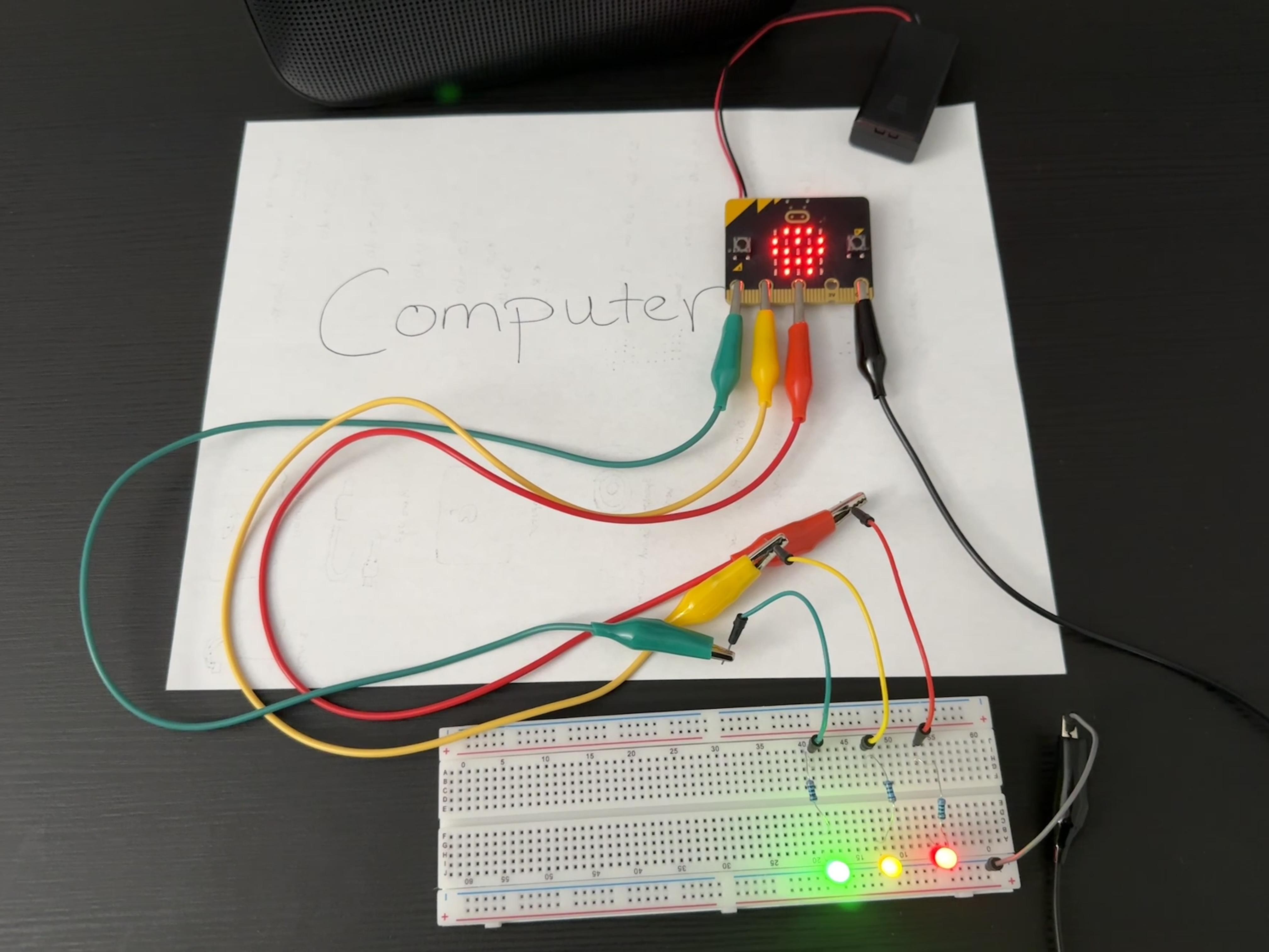
"Turn that down or you'll go deaf!" It would be nice to know if that's true or not. With a Micro:bit and a few extra pieces, you may not hear the alarm, but you'll see it coming with a decibel meter with LED warning lights.
Supplies
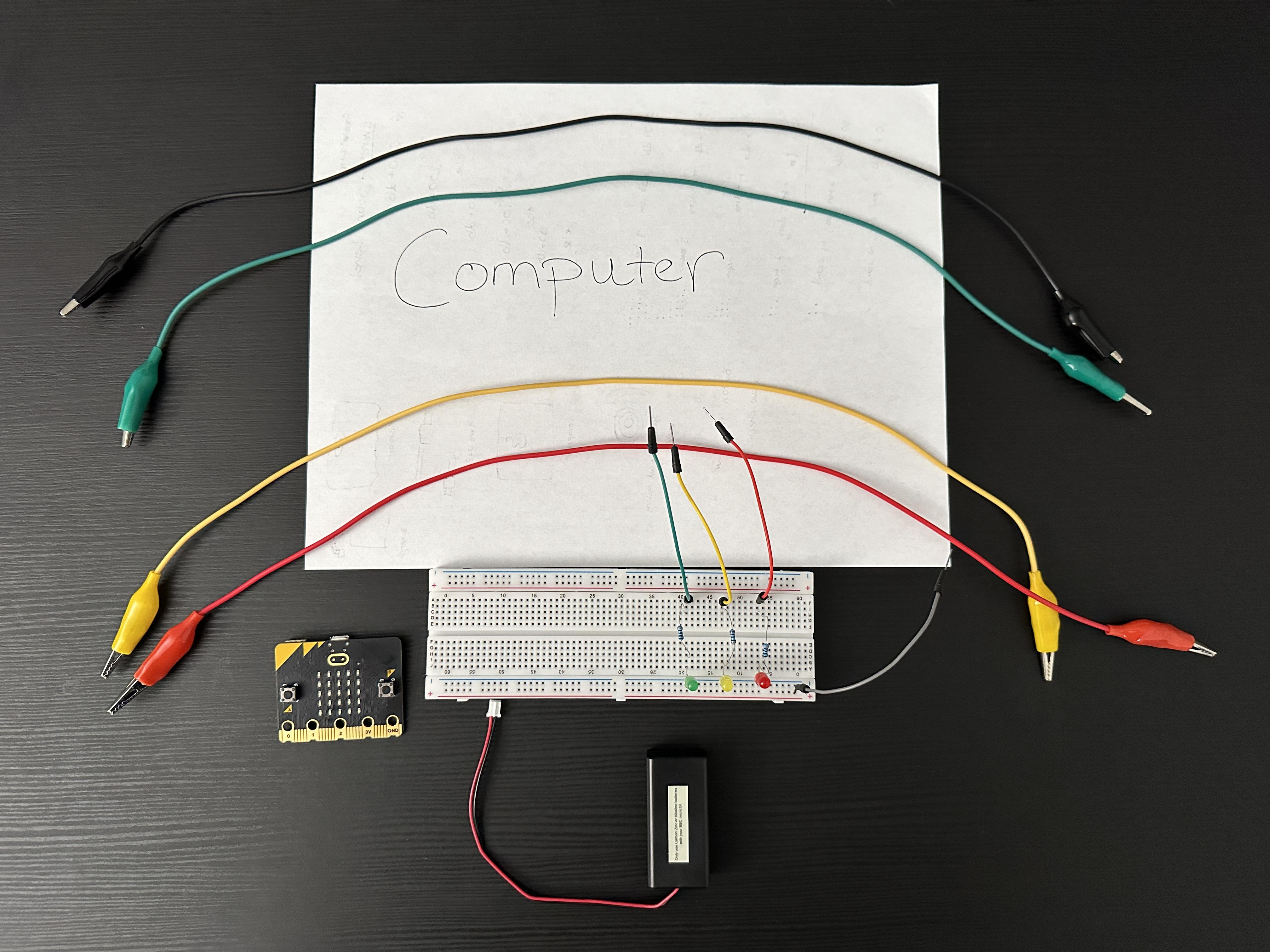

- Computer (not a paper one)
- Microsoft Makecode Micro:bit account
- Micro:bit (with battery pack)
The items below can sometimes be purchased as a kit from a local electronic store. Shout out to Central Computers and their Raspberry Pi kit.
- Breadboard
- 3 LEDs (red, yellow and green used in example)
- 3 resistors
- 4 alligator clip wires
- One end can be stripped and prepped for direct connection
- 4 prepped wires
Become Familiar With Makecode
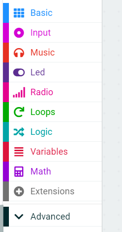

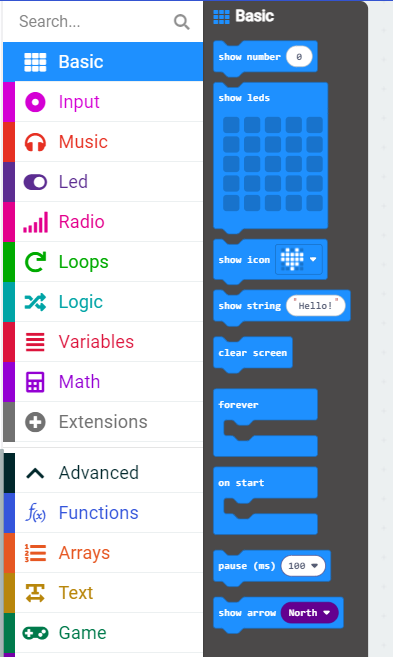
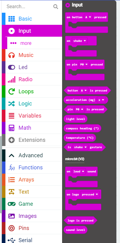
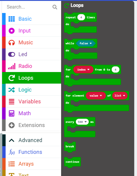
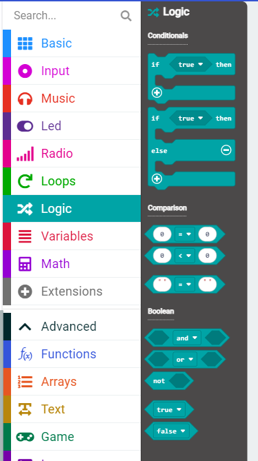
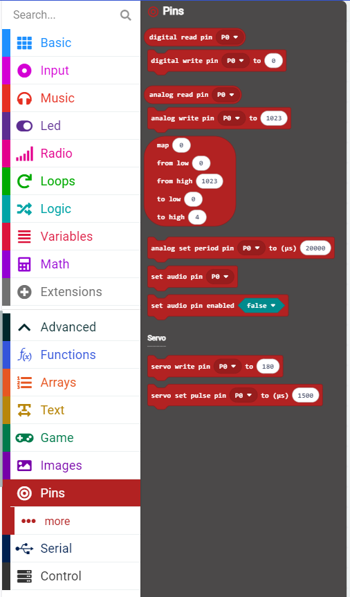
Set up a Microsoft Micro:bit account, and begin a new project. If you aren't familiar with block style code, it may be best to start with one of the tutorials offered first. If you have already done one or two, then this is not too far of a stretch.
It's important to familiarize yourself with the various tabs you'll need to get your code blocks from. The initial menu has most of what you need (pic 1), but there is an additional tab in the advanced section (pic 2) that we need as well. You can simply click on the block you need and that will place the block in the coding area. You can always simply duplicate what you need, or you can go back and grab blocks as you need them.
Let's list out the [code blocks] you need from each section, along with the total amount:
Basic (pic 3)
- [Forever] -1
- [Pause] - 5
- [Show LEDs] - 6
- [Show number] - 6
- Optional-one additional
Input (pic 4)
- [Sound level] -11
- Optional - one additional
- Optional - [on button "b"]
Loops (pic 5)
- [Repeat 4 times, do] - 4
Logic (pic 6)
Conditional
- [If true then, else] - 1
Comparison
- [0 < 0] (any comparison block would do really) - 5
Pins (pic 7)
- [Digital write pin P0 to 0] - 12
Let's Build This Program, Block by Block
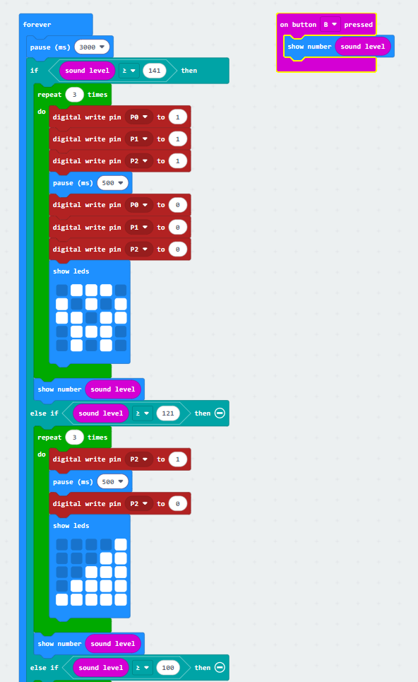
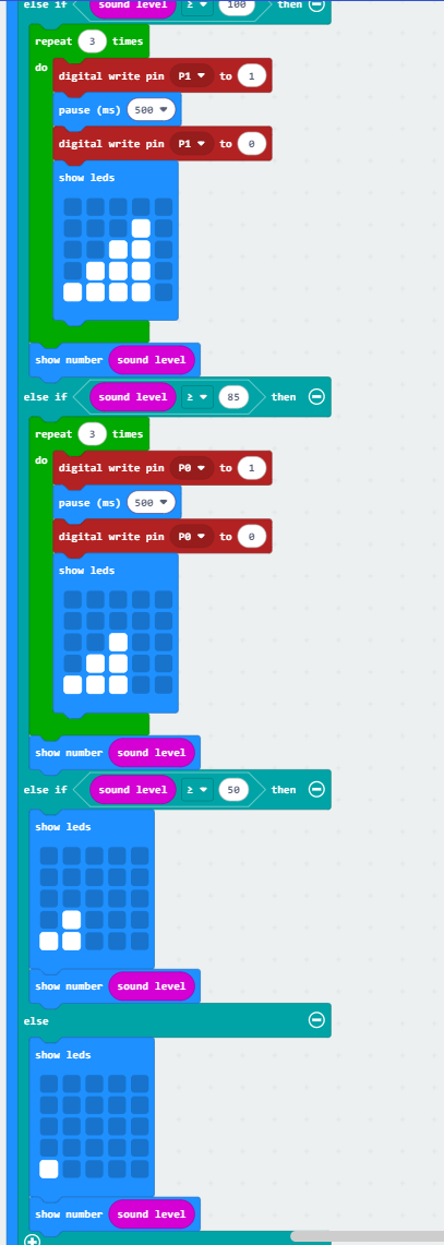
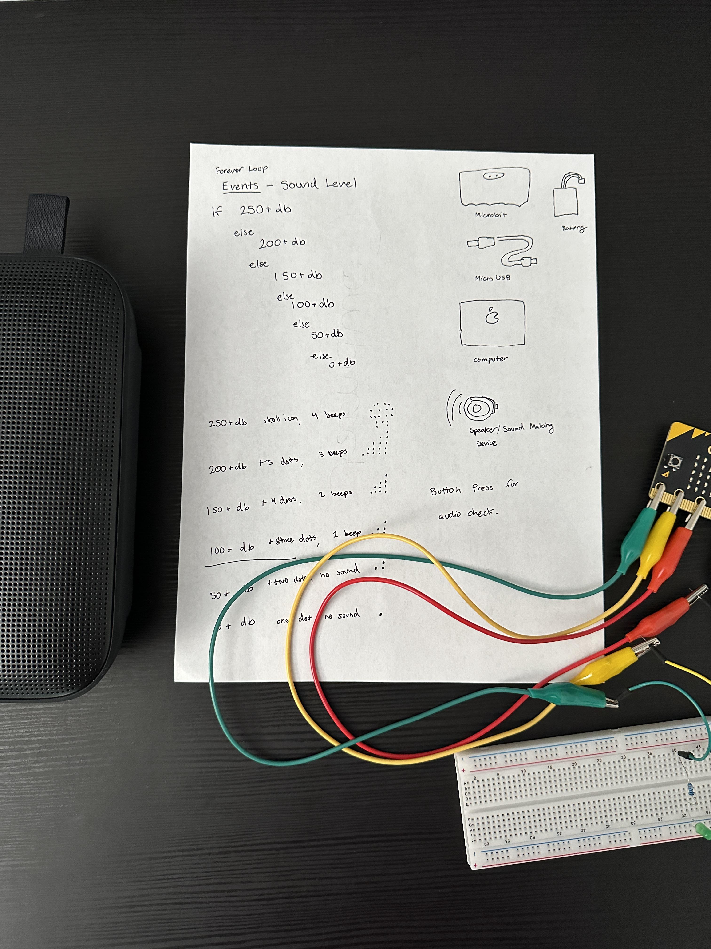
Take a look at the program in the first two images. This is the complete program. While I won't go step by step with what to do, since it's highly visual, I will discuss the order and why things are where they are. I have also included my original plan, to see where I made changes, as well as the hex file itself.
The program starts on a [forever] command, meaning the program will run continuously while there is power. Everything needs to go inside of this.
The [If-Else] block nestled inside is really about the order you want your cause and effect to show up. Since the theoretical default is a very quite area, then the lowest decibel read is at the bottom of the order. The program should continue to move down a list until it hits the right conditions, hence the if-else. "If it's not this loud, then let me check if it's this loud".
I chose the decibel levels based on thresholds of hearing from this site.
The [pin] blocks are about sending signals/ currents to the assigned parts on the Micro:bit. They have to be in pairs of off (0) and on (1). I chose to do this stop light style, since we're used to it. Of course, if the decibel level is too high then it's best to get attention anyway you can, with all of the lights in this case.
The [show LED/ show number] blocks are redundant, and if you want to take either out, you can. Originally, the LED designs were connected to sound, but with a Micro:bit sound takes up the 0 pin slot. I took out the sound, but the visual scale remains. This is also why the [On button B press] exists, to check the meter to see sound thresholds.
The [pause] blocks are necessary to create buffers in some of the actions, such as ligthing the LEDs long enough to be visible.
The [repeat] block was paired down to three for timing purposes. I felt three visible flashes was enough.
Downloads
From Software to Hardware
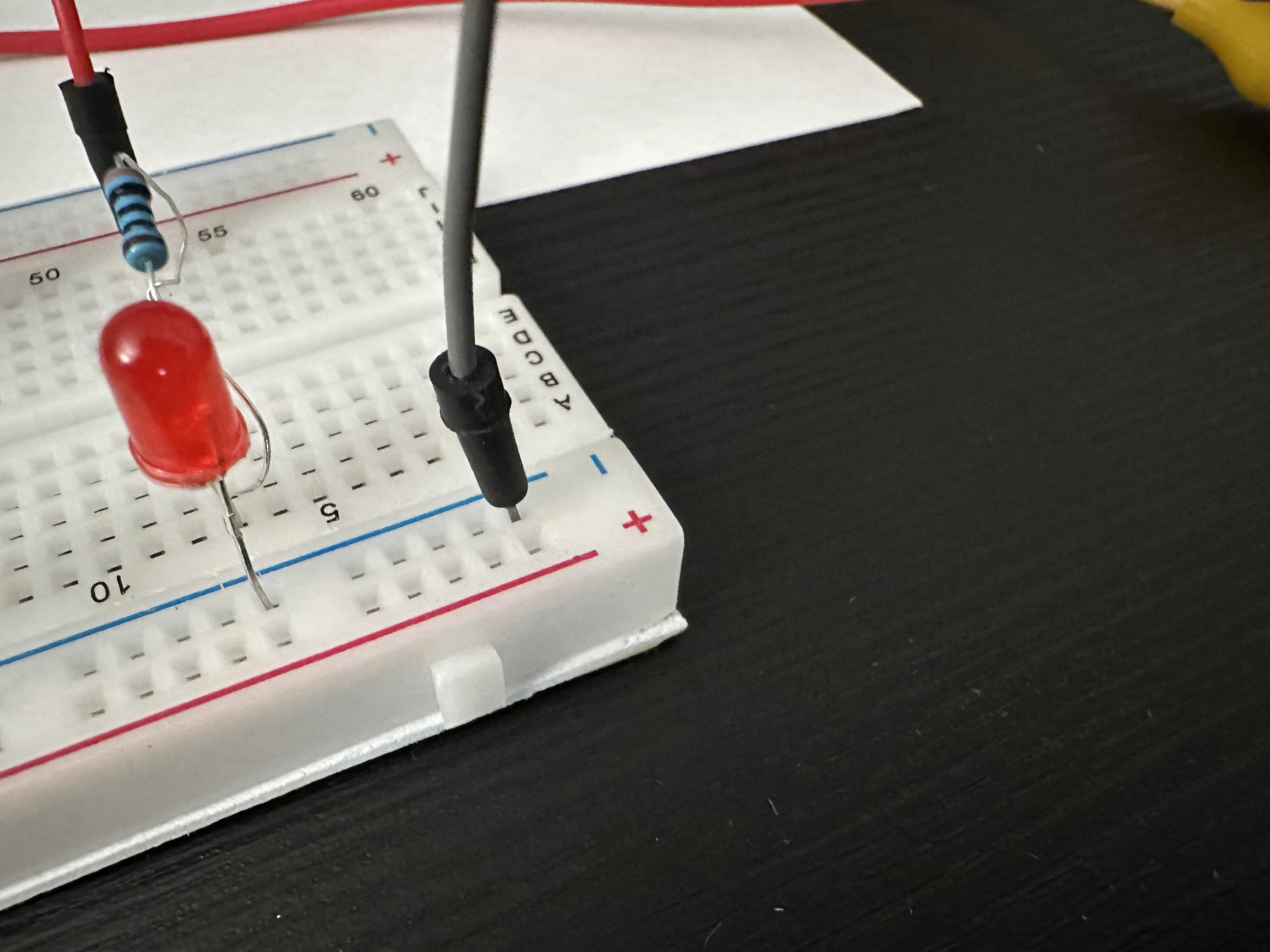
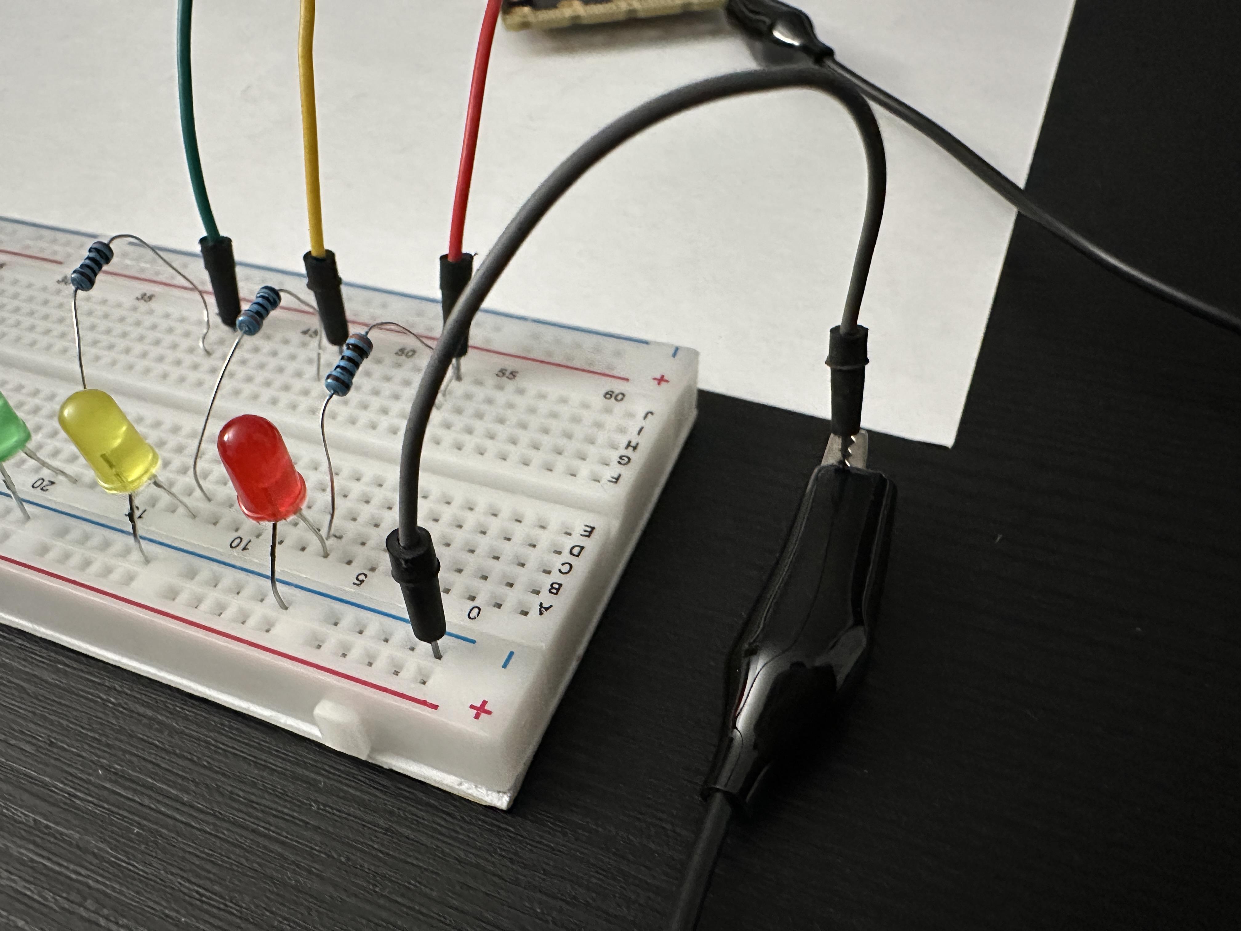
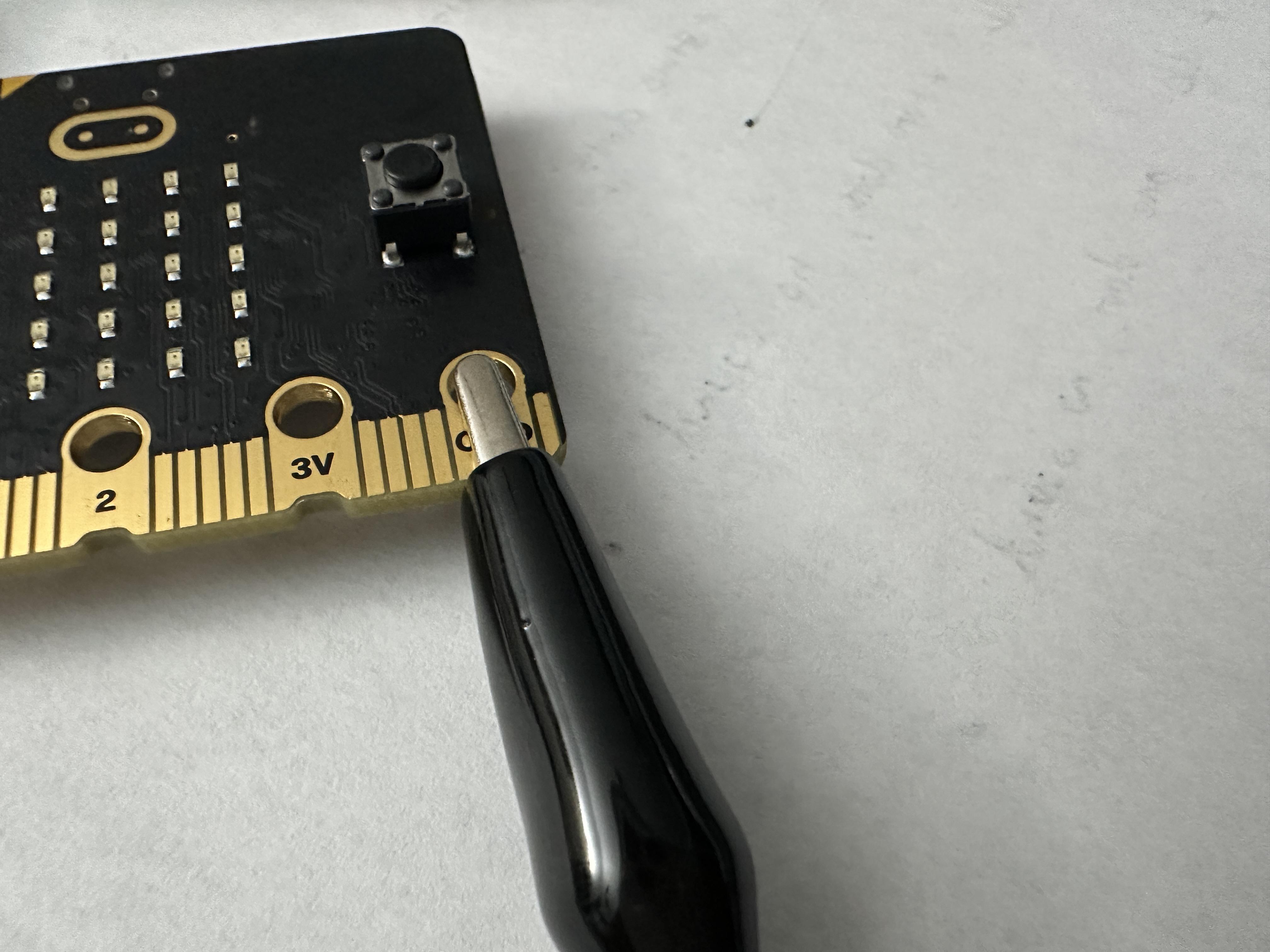
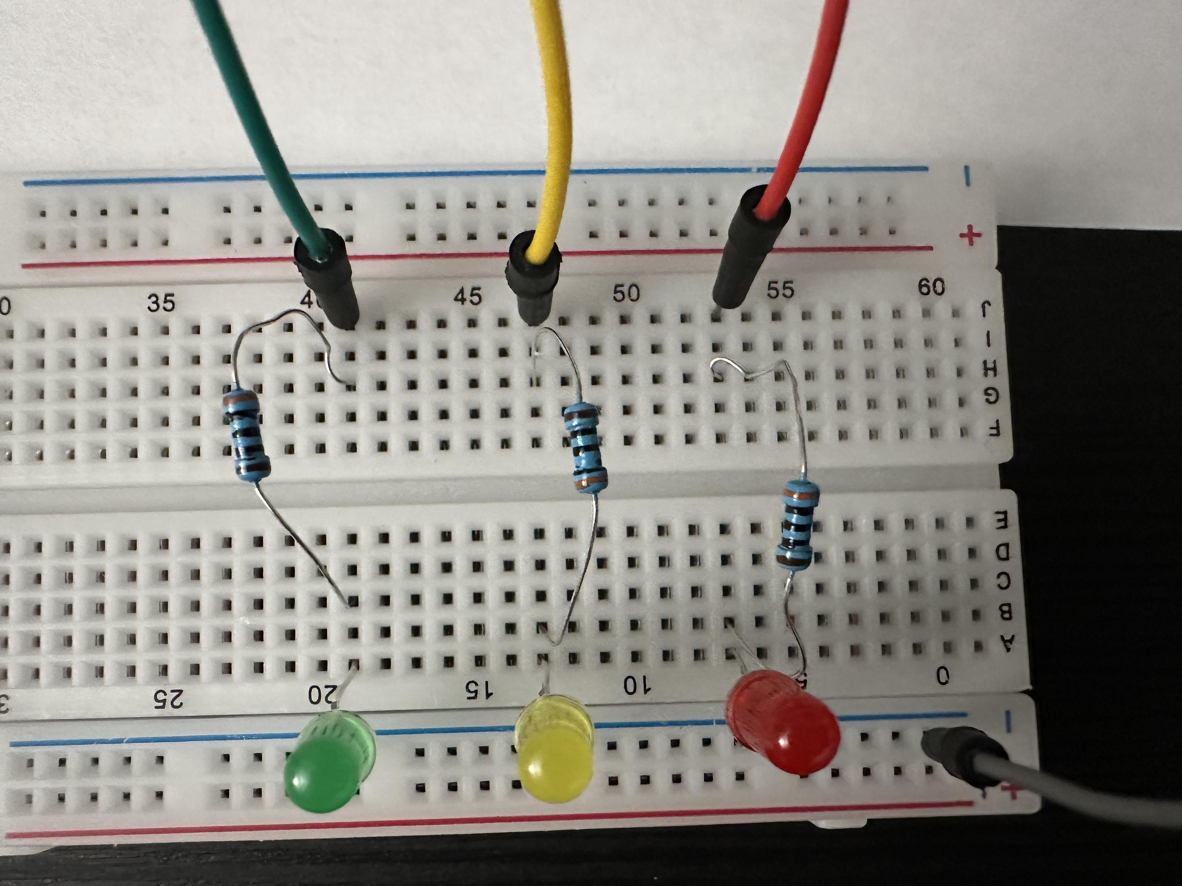
Now that your program is running, and hopefully checked on the emulator side of things, let's see how this works in the physical world. Once you have uploaded the program into your Micro:bit, you can preplug some elements in for test.
First aspect to set up is the ground wire. Begin with plugging in one of your wires to the negative (-) row of holes at the edge of your breadboard (pic 1). Connect that wire to one of your alligator clip wires(pic 2). (You can cut and strip a dual sided alligator to have one wire connect directly to the board. I left mine as is for future use). Then clip the ground to the right most area on the Micro:bit labeled "GND" (pic 3).
Once you've set that up, begin arranging the other parts as shown in pic 4. They should all be aligned. On the side of the ground place the LEDs, with the shorter prong on the ground side and column (+/-), and the longer prong in the same row as the ground prong (Row A). Next, place your resistors in the one of the remaining slots (Row B-E) and into the another slot (Row F-I). Finally place a wire into the last hole (Row J). Repeat this with the other LED, Resistor, and Wires.
To make this easier follow this pin guide:
Red LED- Column 5
- LED - Row (-) (short prong) + Row A (long prong)
- Resistor - Row C + Row H
- Wire to alligator clip - Row J
Yellow LED- Column 10
- LED - Row (-) (short prong) + Row A (long prong)
- Resistor - Row C + Row H
- Wire to alligator clip - Row J
Green LED- Column 15
- LED - Row (-) (short prong) + Row A (long prong)
- Resistor - Row C + Row H
- Wire to alligator clip - Row J
Check the LEDS
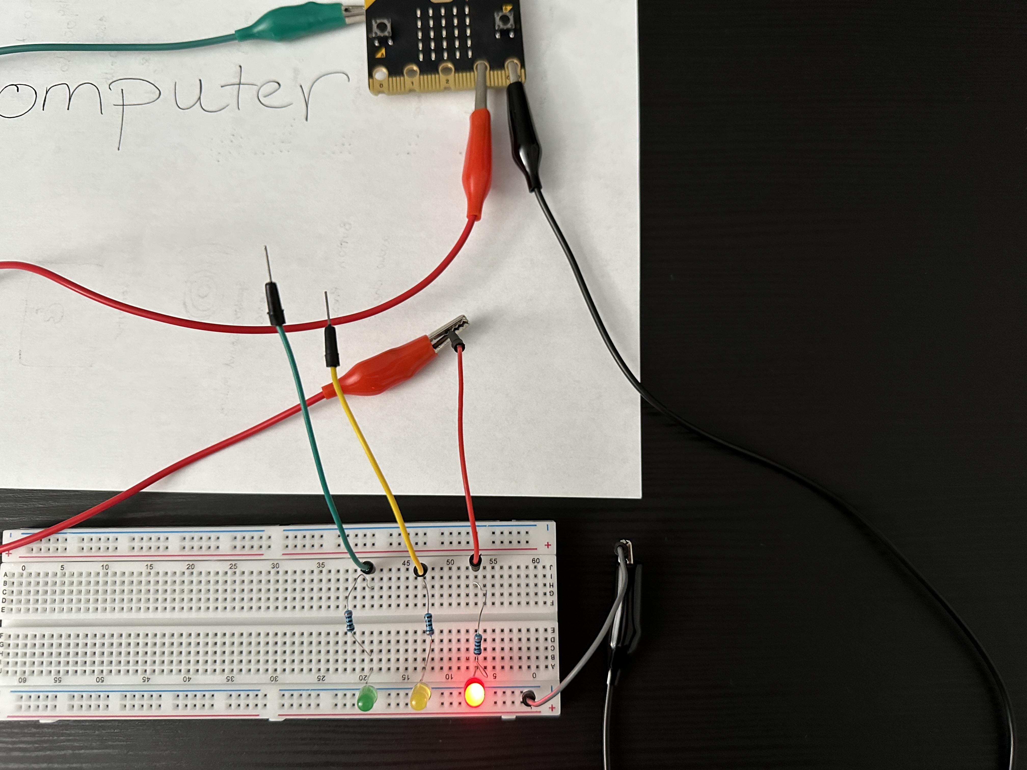
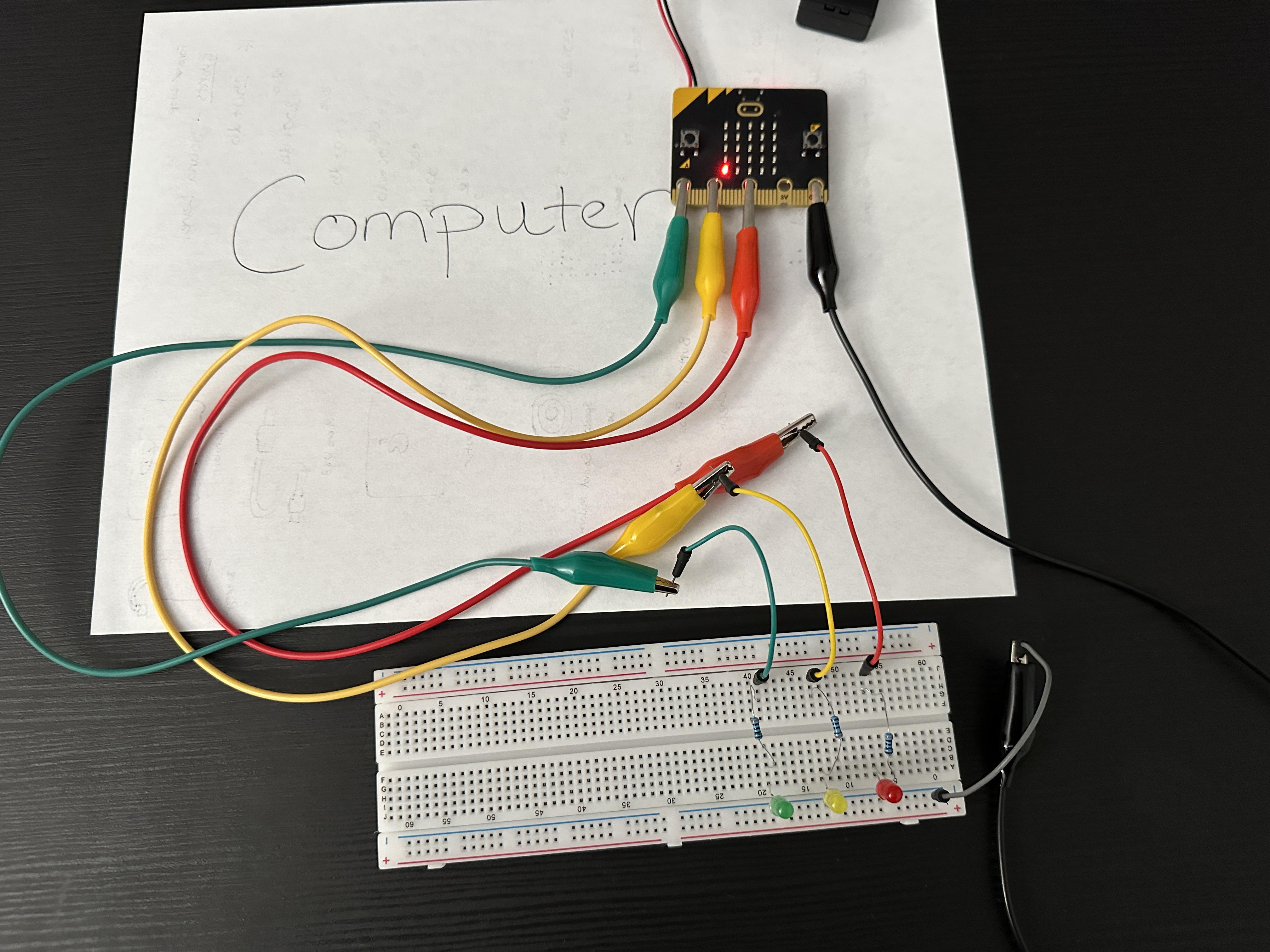
Once your breadboard is set up, it's time to check the setup. Plug the power supply into your Micro:bit. It has a "3V" area where power is consistently going to that pin. When you connect the alligator clip to the corresponding wire and to the 3V, it should clearly light up. If it does not, check the connections, ensuring the wires are securely connected in the holes, and are aligned in the proper columns/ rows.
You should individually check each LED, but if you're confident, you can simply move on to testing.
Sound the Alarm
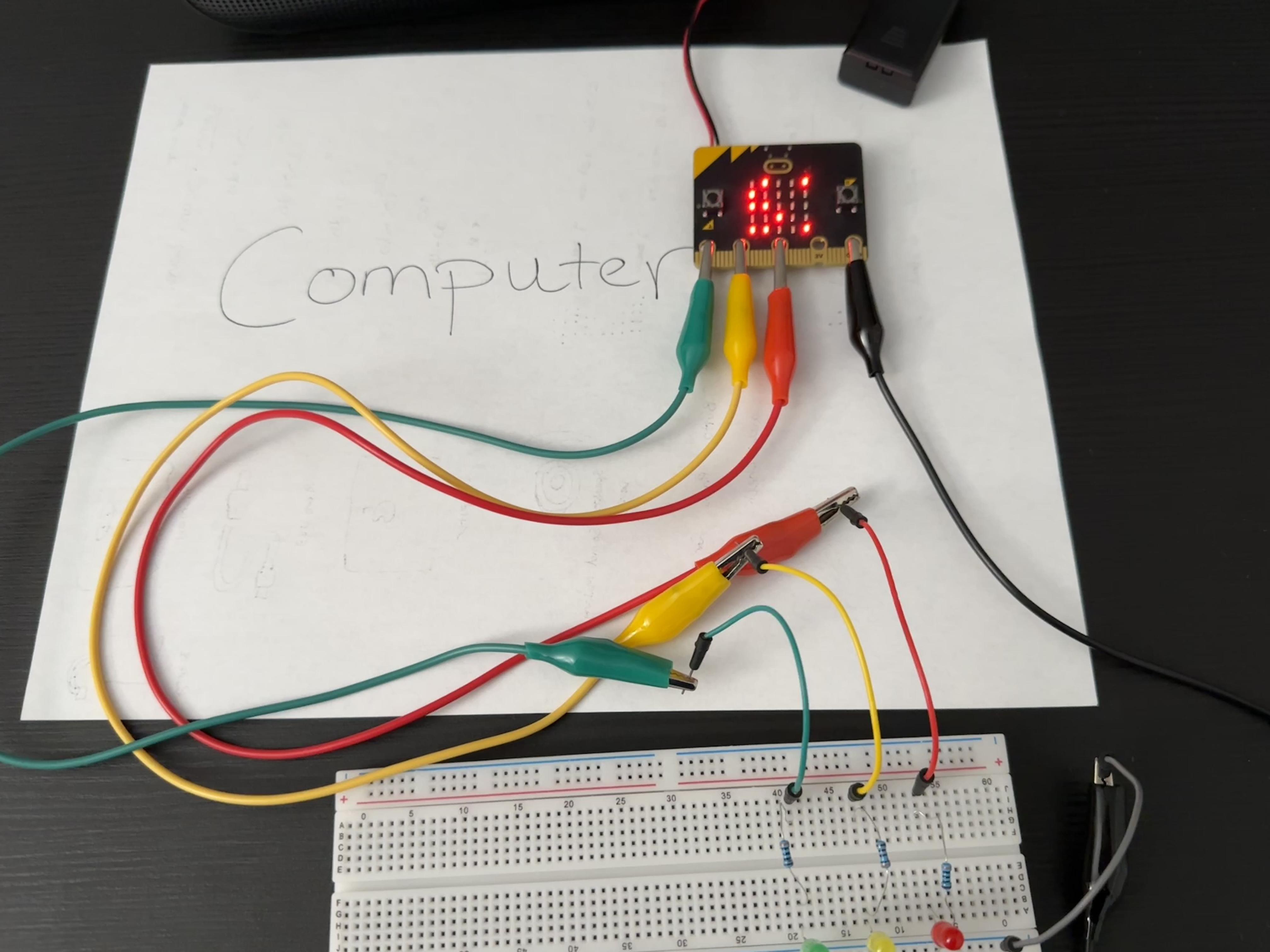
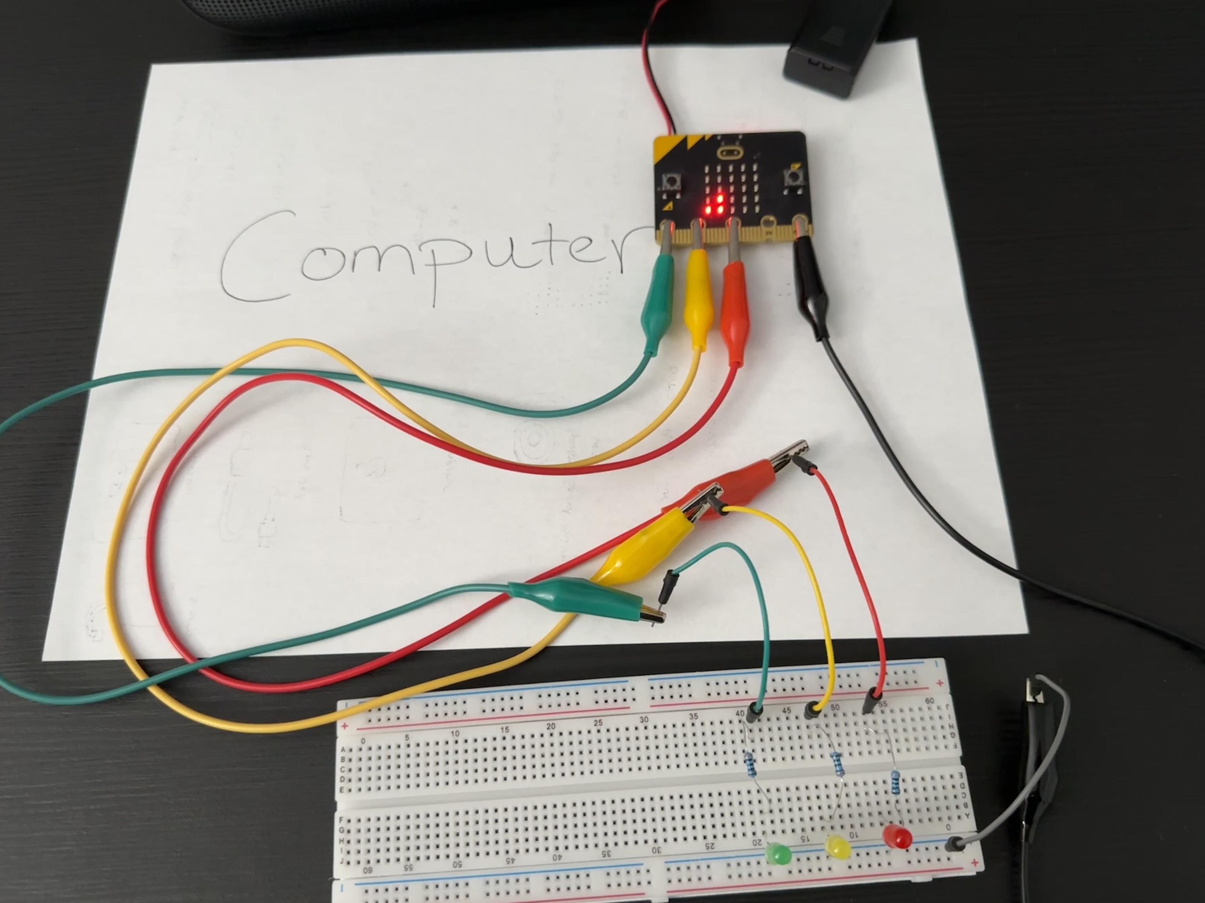
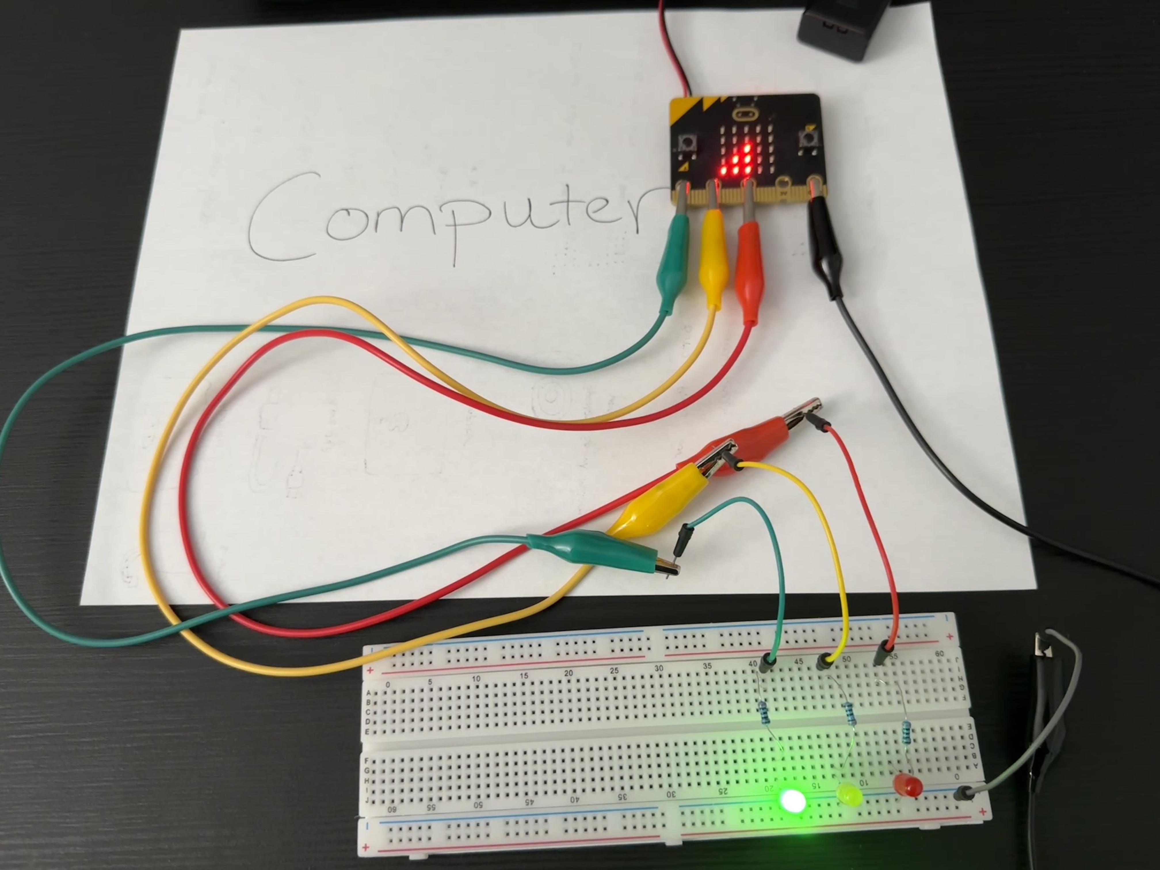
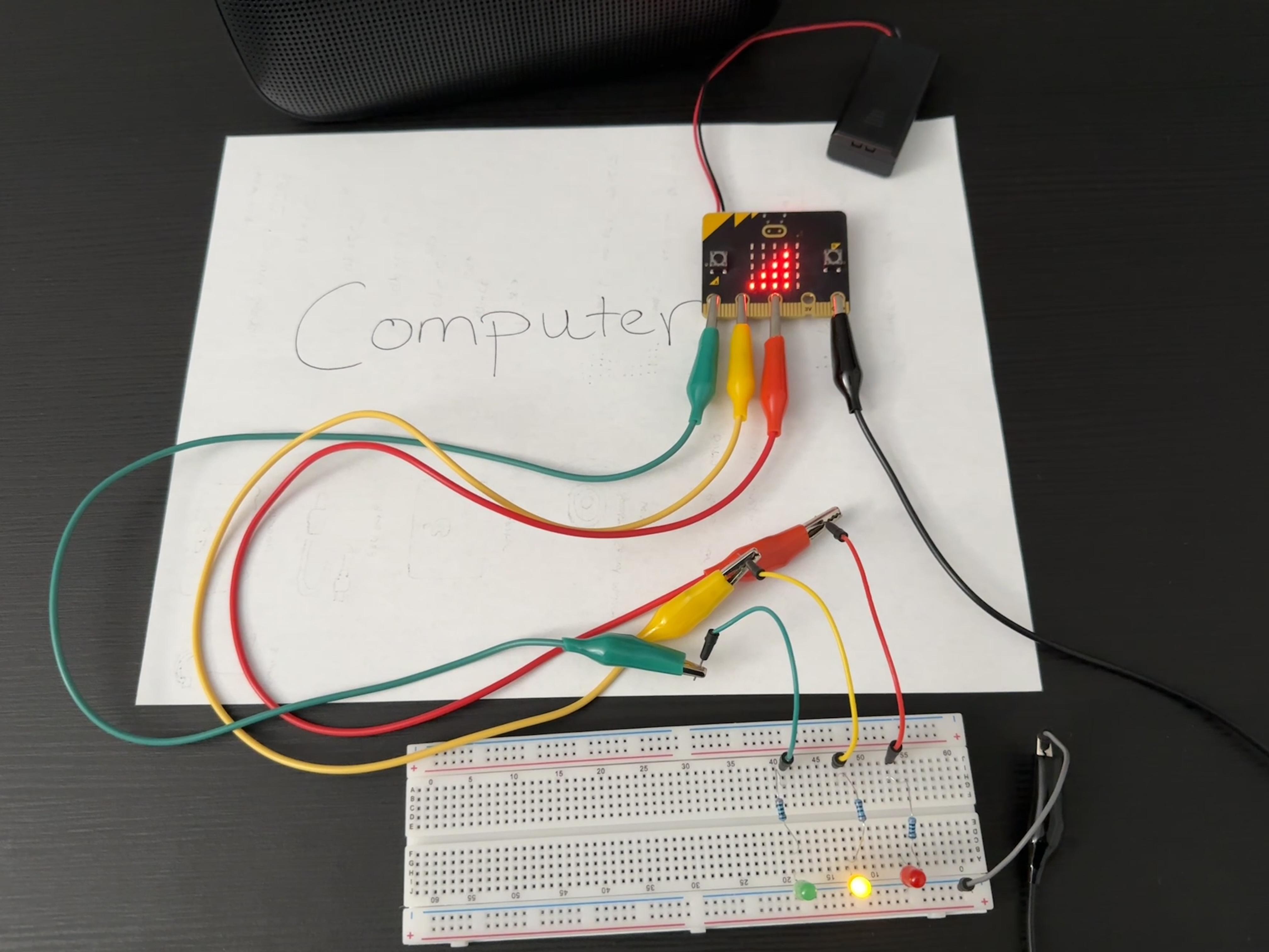
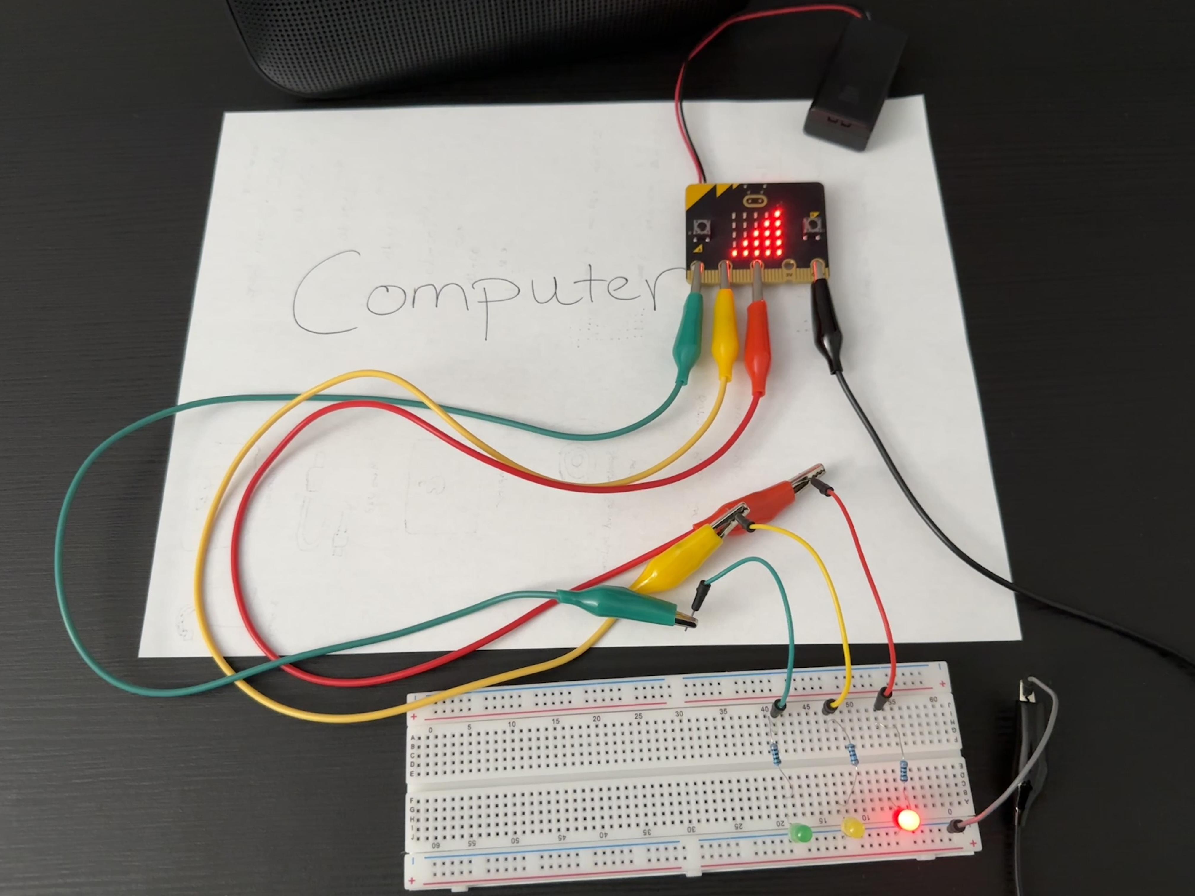
To test your new decibel meter, your phone is usually enough to get the LEDs to light up. I have tested it with my phone alarm, but in the picture I tested it with a small speaker and a pop song. Begin at a low volume and gradually move up as the meter registers higher decibels. Ensure that the LEDs are flashing as expected.
Once it's all checked out, enjoy your decibel meter!
Video Proof
While the video file is too large to upload, here is a link to the video in my google drive.
Reflection
What kind of Project did you do? How did you decide what to pick?
- My project is a decibel meter and alert system. It is meant to flash lights and show the decibel level at the time the microphone activates, which is on a forever loop every 3 seconds. I mainly decided to use the sound level because of the previous project. I had issues having my “trick die” activate with sound, so I wanted to focus on that particular event to better understand it.
How does your project use external equipment to your Micro:bit, like LEDs and radio communication?
- My project uses LEDs and a breadboard to create a stronger visual alert. The LEDs correspond with the increasing decibel thresholds; green, yellow, red, then all three will flash three times in conjunction with the Micro:bit showing a visual reference and the actual decibel number.
- My original iteration of the project featured sound, but that led to one of the pins being dedicated to sound, so I made a change in order to incorporate more LEDs. The breadboard made it much easier to use a single ground for the LEDs.
Describe something in your project that you are really proud of getting to work.
- I am really proud of simply getting this to work better. Initially, I chose the levels because of the minimum and maximum levels. Taking a little bit of time to look into decibels helped to make this more authentic. I’m also proud of being able to use the breadboard. It feels good to use peripherals, even if it’s something this simple.
Describe a difficult point in the process of designing this program, and explain how you resolved it.
- The initial process was mostly difficult because of the lack of understanding and parts. Having never worked with programming pins, it was not part of the original design.
- Once we worked on the project in class, it showed some limitation on what the pins could do, with 3 being programmable and 2 not. Additionally, my use of sound caused the first issue, as I couldn’t program the pin as it was dedicated to making sound (I still don’t understand why, but it was clearly shown both in the emulator and with the physical Micro:bit).
- Showing off the work was enough to wrap my head around the issue and simply remove the chime to free up pin 0 to wire with an LED.
What feedback incorporate into your enhance prototype based on students peer feedback during the in person class?
- There wasn’t any particular feedback that helped. Additionally, I don’t feel we had enough time between people’s show case to give good feedback. I would request a small amount of time to write and share next time.
How might things have been different if I programmed the assignment in Python?
- I’m unfamiliar with python from a practical standpoint. I am looking forward to understanding better how it might change. From what I understand, I would likely remove the show LED aspect, as it would be easier to simply display the current decibels.