Darth Vader Shadow Casting Box
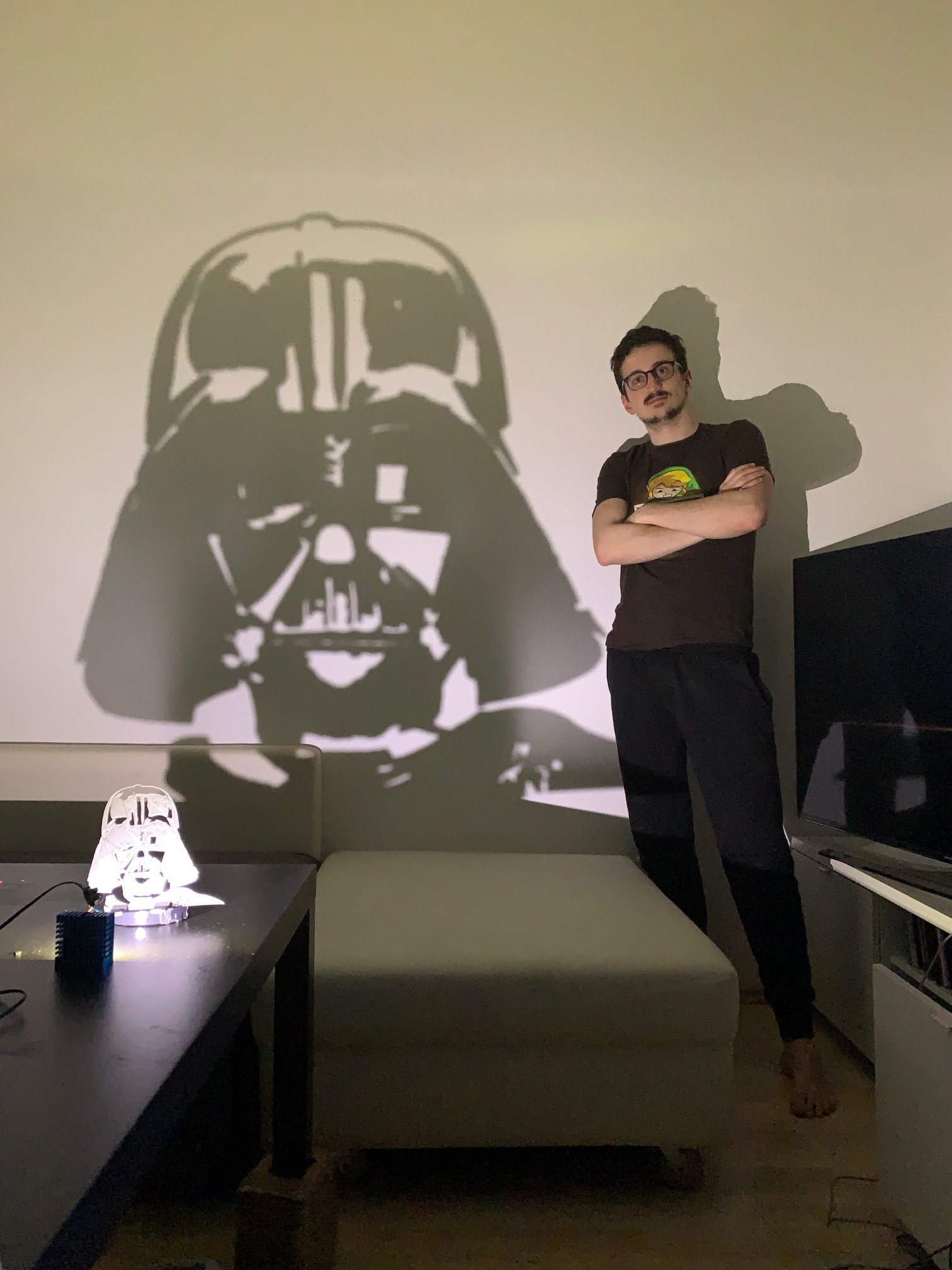
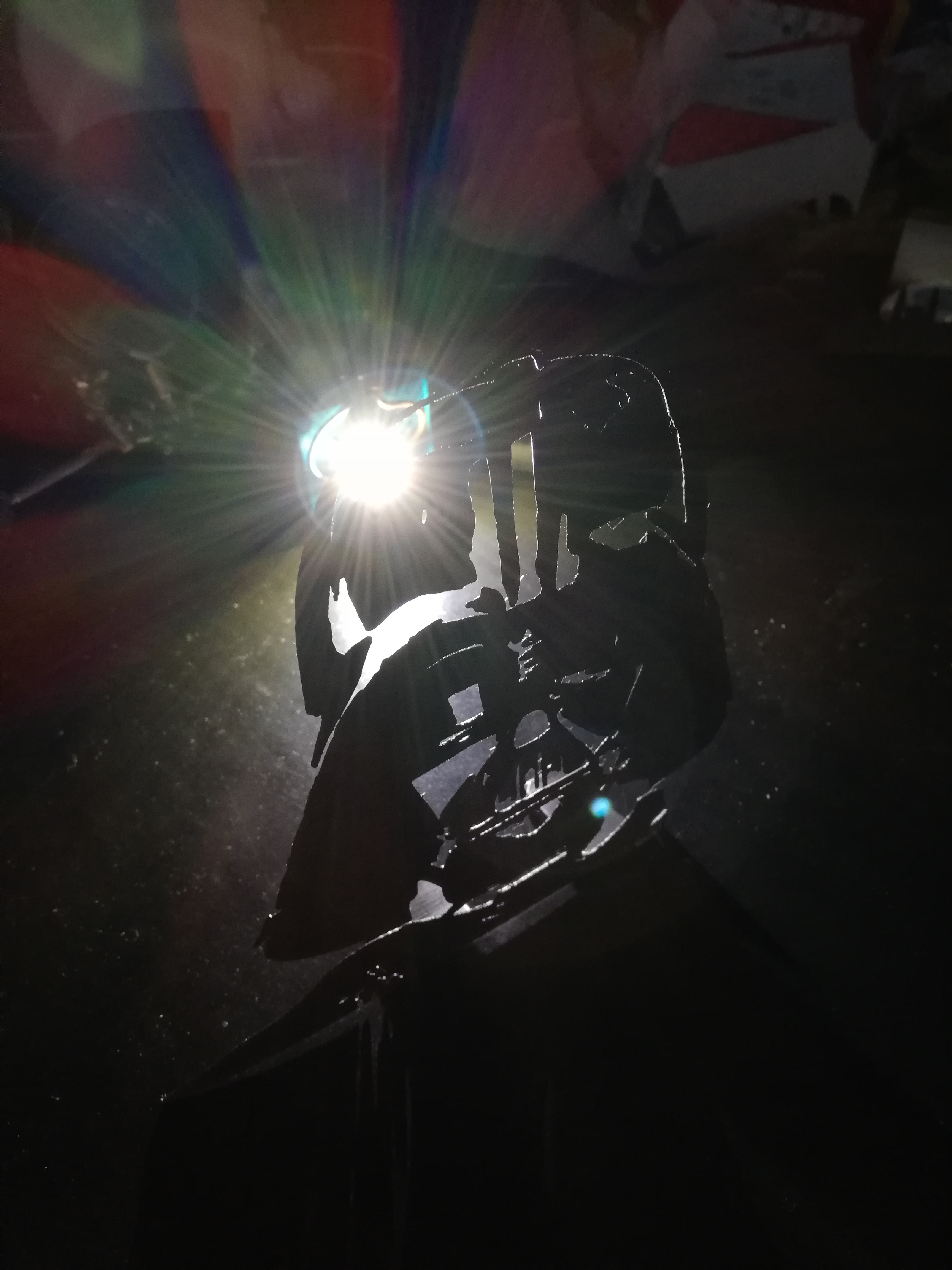
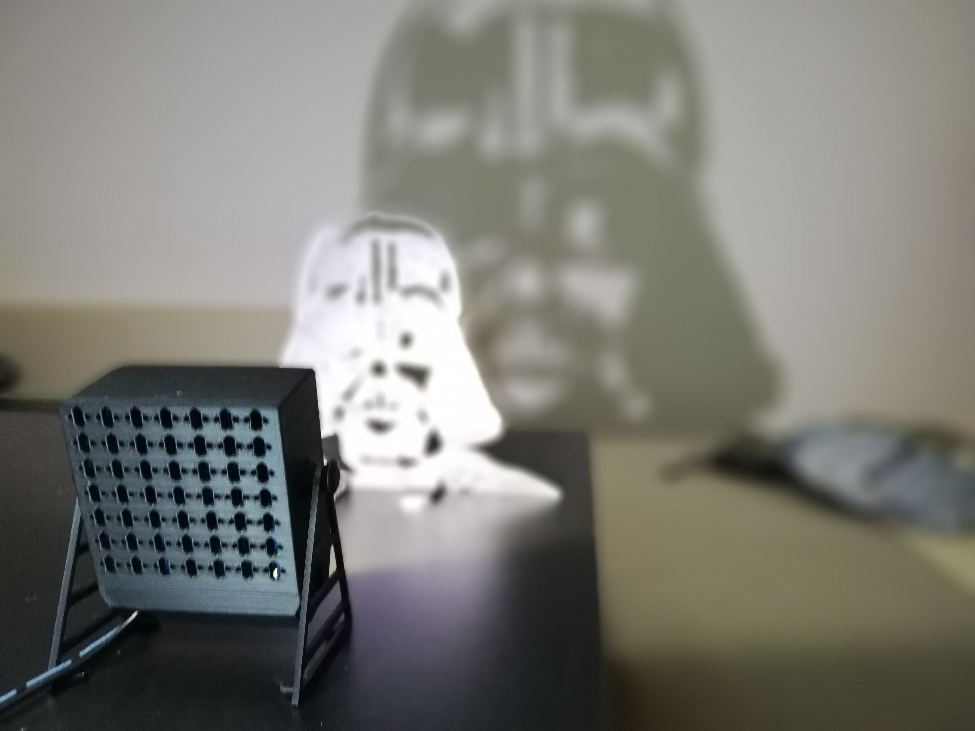
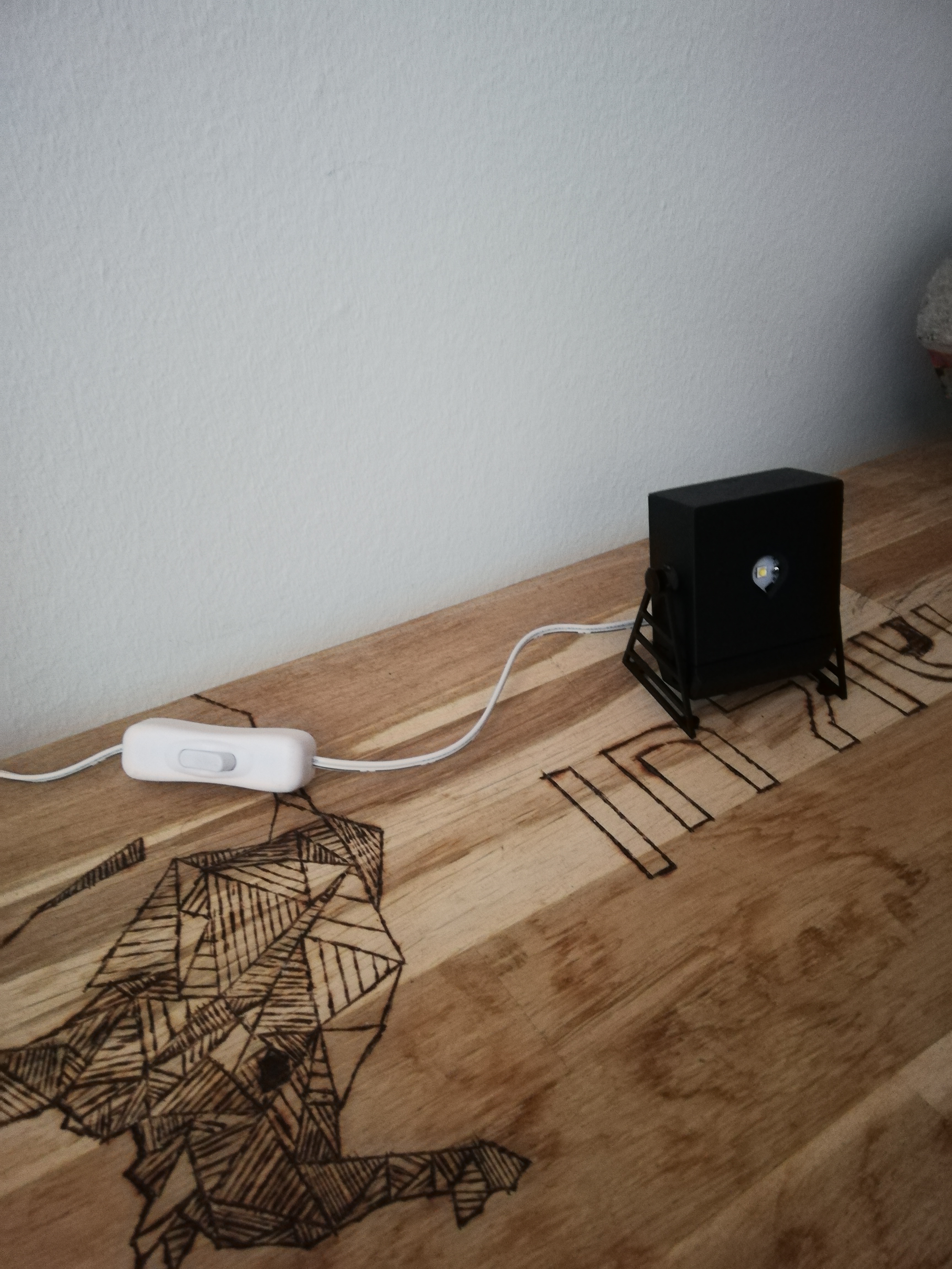
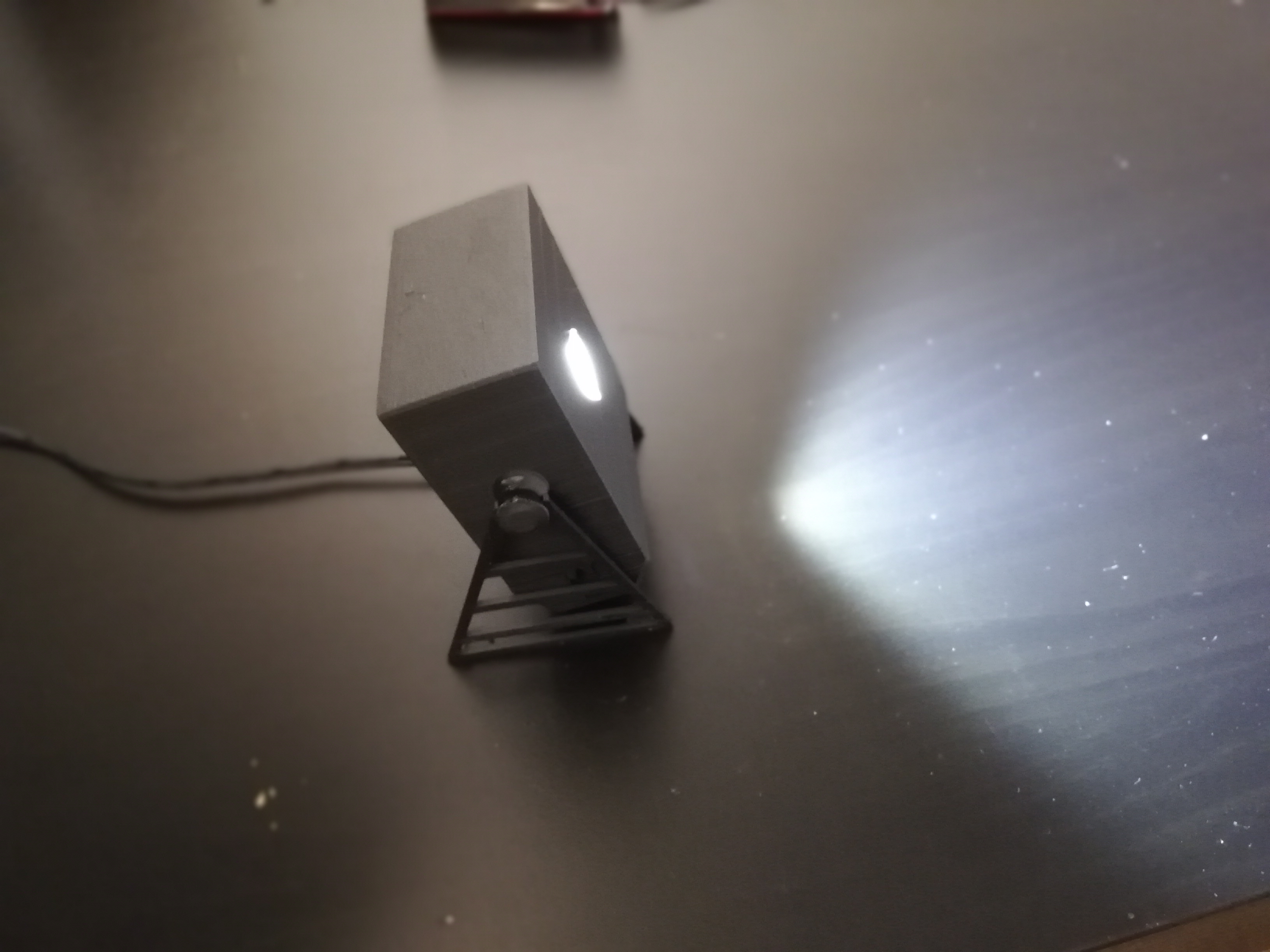
In this instructable, we will go through the steps to build a darth vader shadow casting system. It is a great way to have something similar to a wall tattoo, except it is not permanent and can be changed at any time (for example to project a city skyline…).
I will not
get into details on how I created the 3D model for the Vader. But here’s a quick guide, in case you wish to project something different:
- Find a picture you want to project, it must be quite simple and possible to represent with only black and white
- Go into your favorite image processing software (in my case gimp, which is free) and threshold the image to a black and white image.
- Use some orphological image processing steps to clean the image (open / close or erode dilate). You want to get rid of the details in the picture. Then make sure to connect all black parts together / delete hanging black spots.
- Convert the file to svg (for example with this site with the option "monochrom") then import it into fusion360 and extrude the sketch.
Components and Tools
Components
For this project you will need following components:
You can use
basically any high power LED, important factors for choosing are following:Chose a single LED with the smallest possible light source size. The smaller the light source is, the sharper of a shadow casting you will get (which is what you want)
The temperature. If your LED is very bright, it will probably heat a lot. I use a heat sink, make sure to use one of adapted size (otherwise, you might melt your Light box down if using PLA).
Watch out for power supply (tension / current), depending on your LED you might need another power supply. The Tension should match the one of the LED (in my case 2,8-3,6 V needed for LED and 3,1 from power supply) and the current indicated on your power supply must be higher, than the one needed for the LED.
I had a spare power supply with switchable tension, giving me directly 3.1 V needed. I give you the link to a similar one, but any power supply that matches your LED needs will do.
Heat Sink:
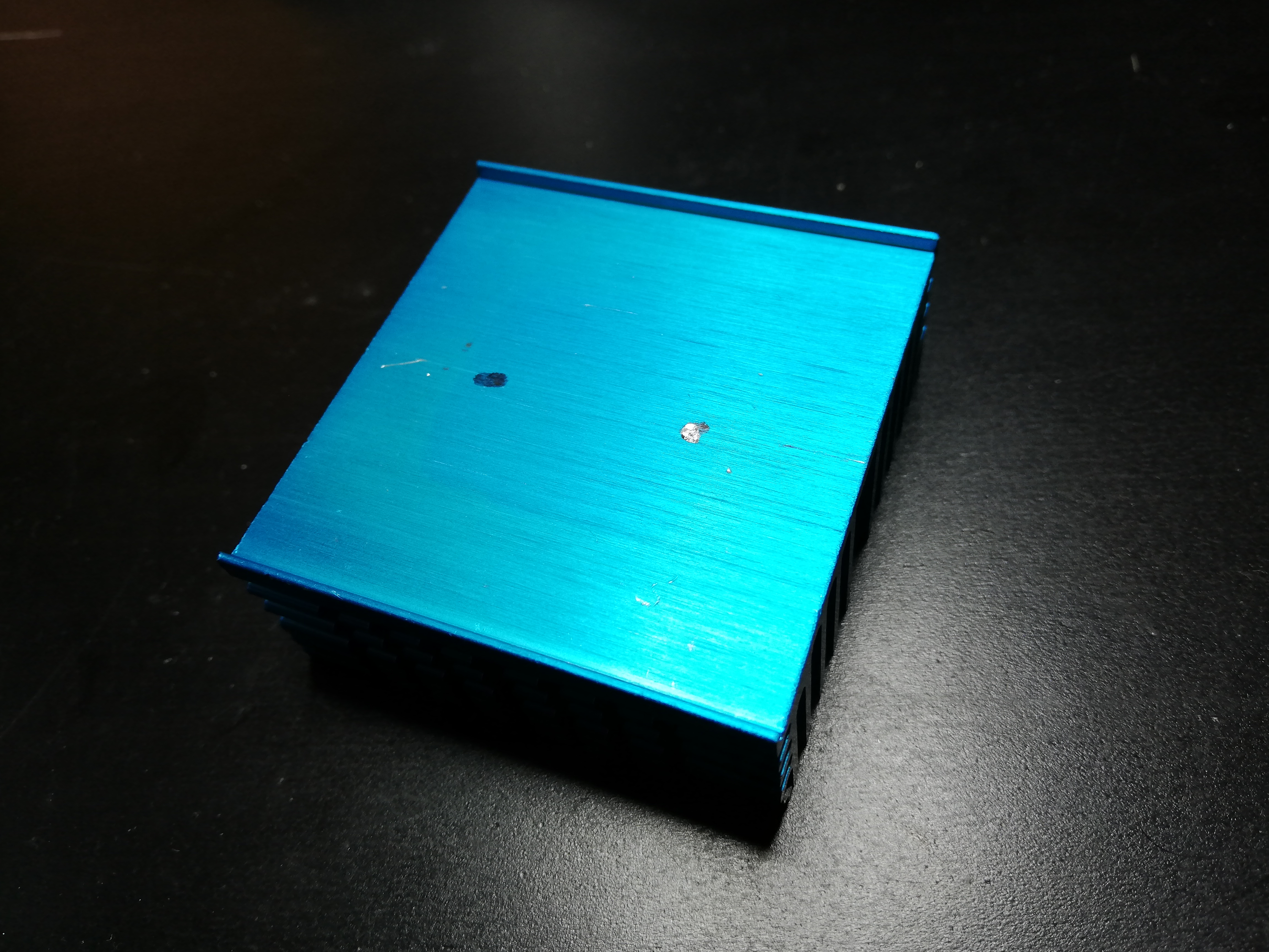
As I said, I recommend using a heat sink, to cool down the LED. This way, you won’t burn your 3d printed LED Stand, and you will increase the lifespan of your LED. I used a spare one with dimensions of 52x50x21. It is more than enough for the LED I got. Even after 2 hours powered on (at 3.1V) it was barely getting warm. So you can go for a smaller one and just glue it into the box or use spacers.
2 x bolt and nut for securing the LED in place on the heat sink
An electric switch (Optional), for switching on and off without having to plug/unplug the light box.
Tools
For this project you will need following tools:
- Drill (if you want to properly mount your LED on the heat sink)
- A soldering iron
- standard electrical tools (screwdriver, wire strippers...)
- A 3D printer or access to one
Working Principle
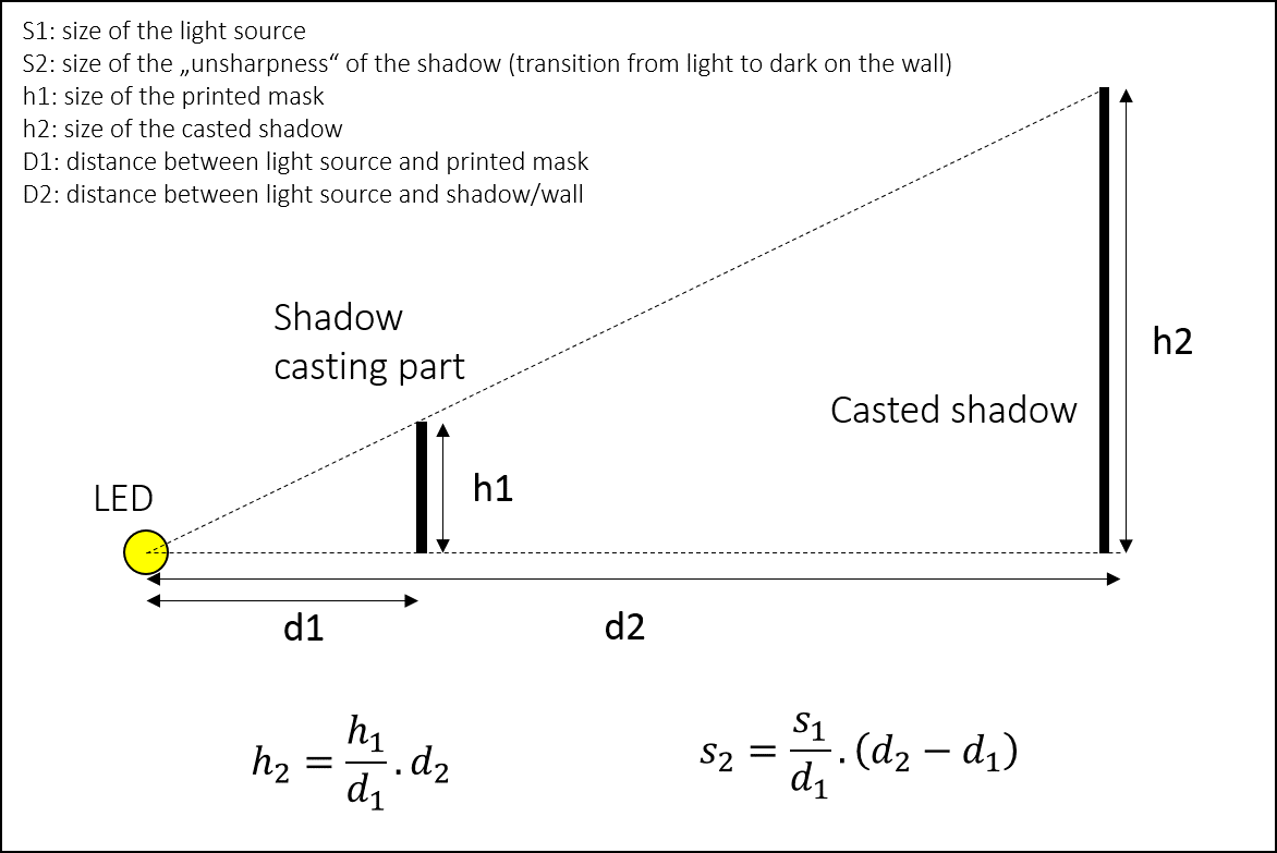
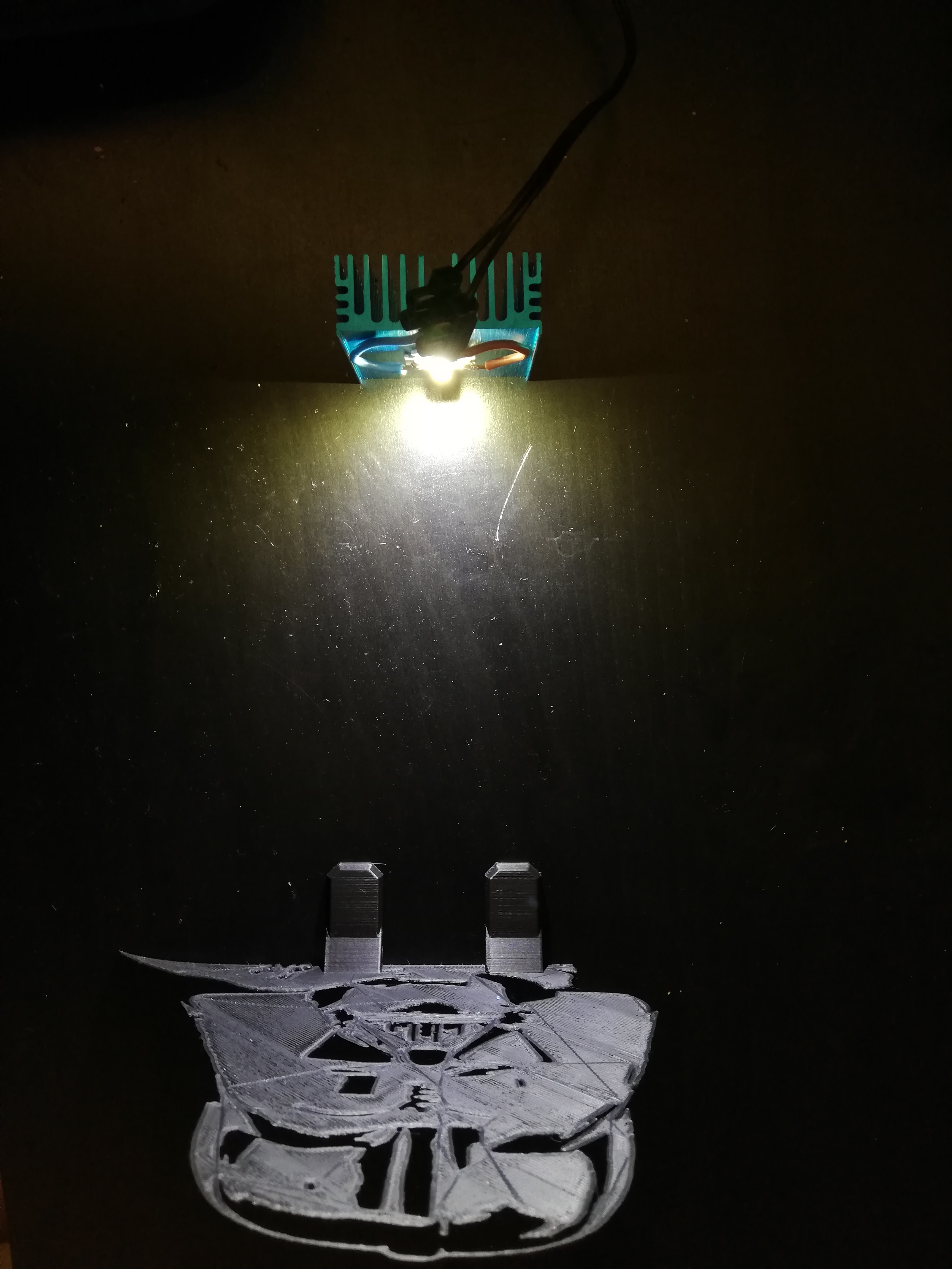
The working principle is very simple. It is based on the “single spot” light source. Since we use a single LED, all light rays come from the same spot in space. Therefore, any object being put in front of the light source will block light and cast a shadow on the projection surface.
The larger the light source the fuzzier the shadow.
The advantage is, that the size of the shadow you cast depends only on two things: the distance between the light source and the “shadow-casting part” and the distance between the part and the surface you want to project it on (wall for example)
You can calculate the size of the shadow with the intercept theorem (also known as Thales’ theorem), as well as the size of the transition between light and dark surfaces on the casted shadow.
So it is a trade-off. For one particular setup, if you want to increase the size of the shadow you can:
- Reduce d1 but increase s2 (so worse sharpness of shadow edges)
- Augment d2 but increase s2 and getting a lower contrast between dark and light areas (since the LED is further from the wall, there is less light coming to the same surface).
Printing the Parts
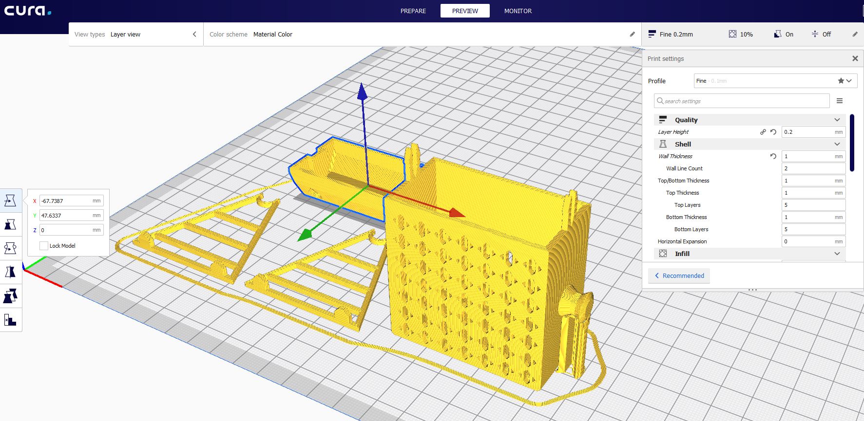
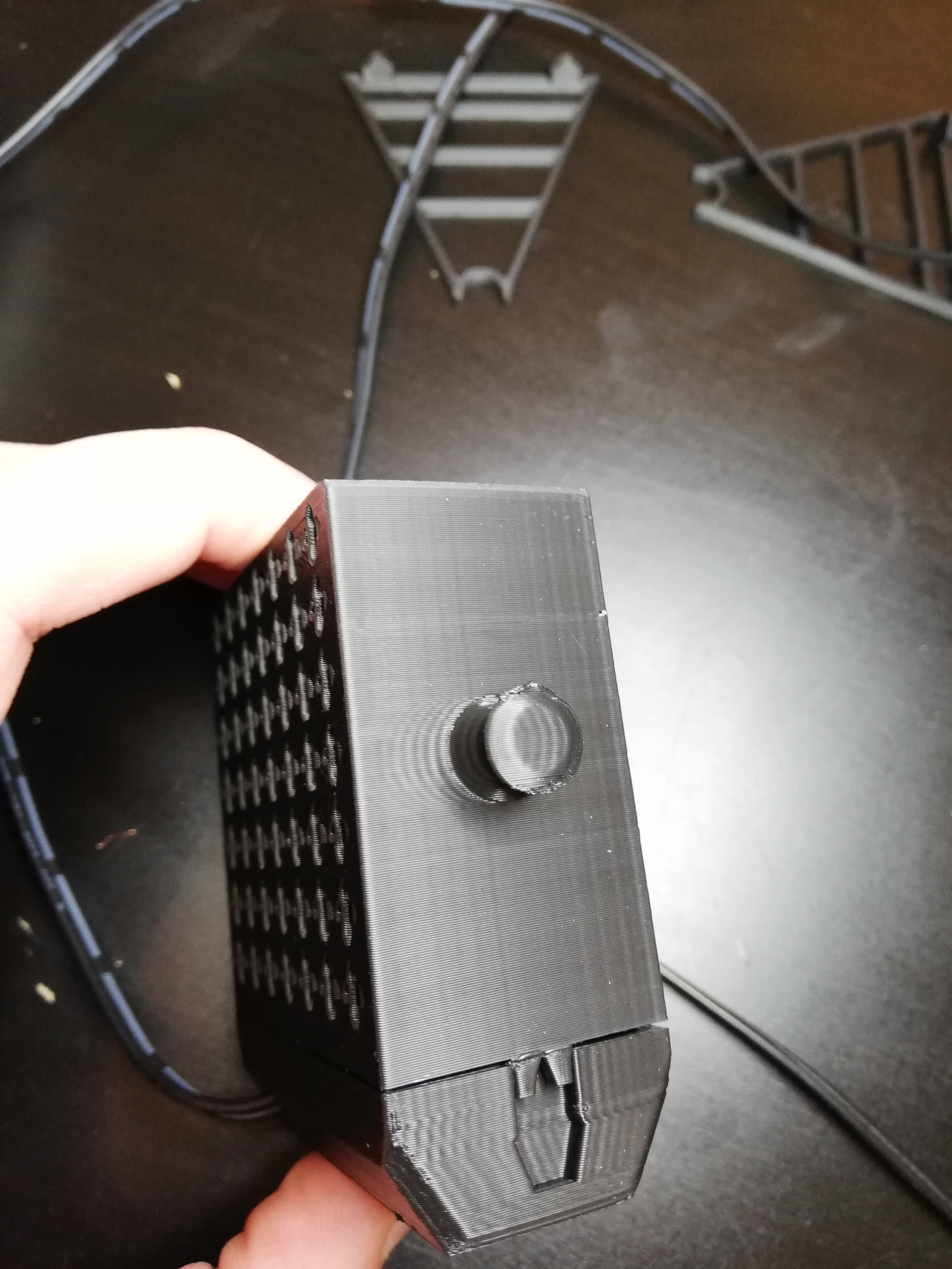
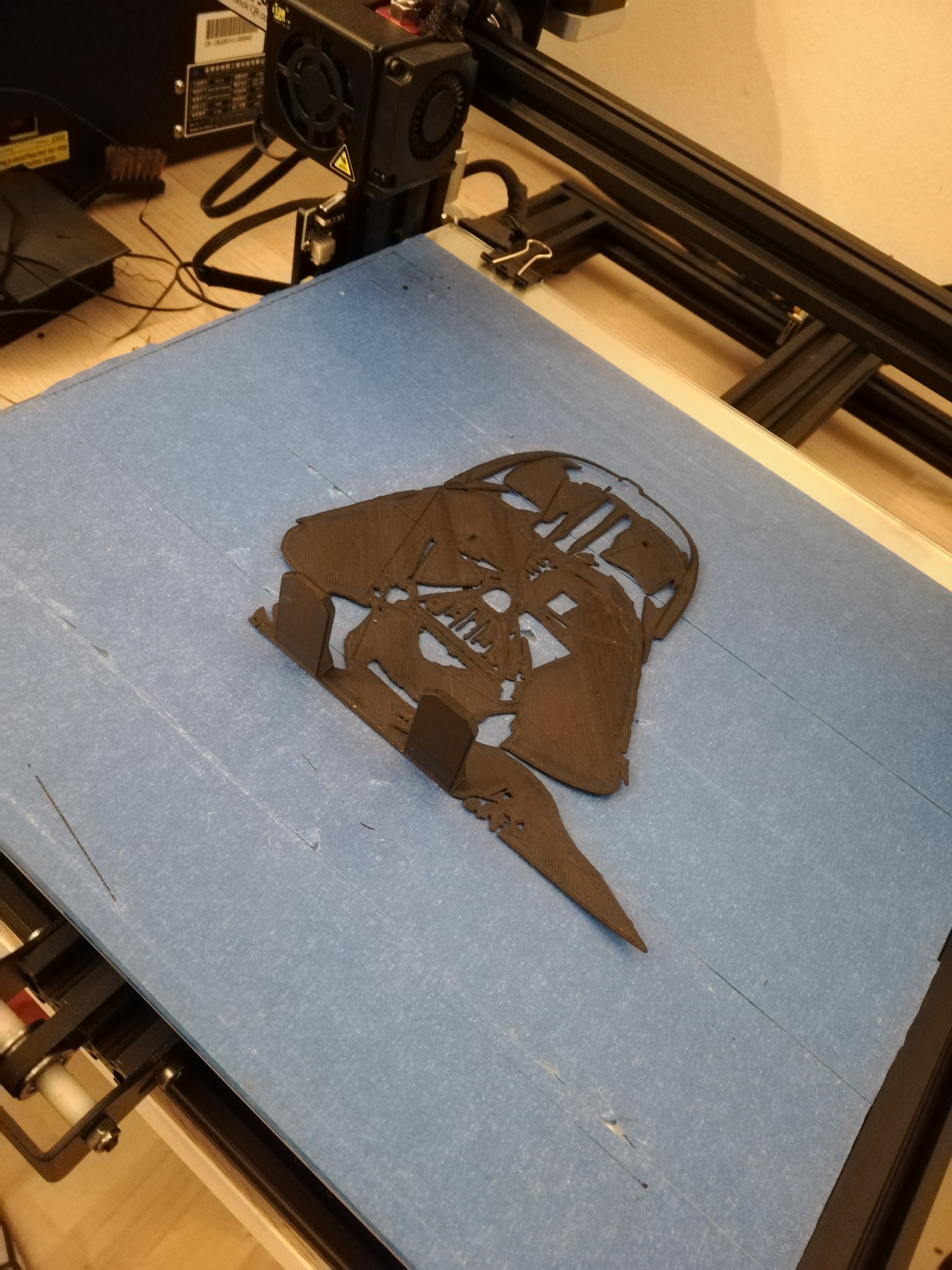
All files can be found on my Thingiverse, as well as other patterns to 3D print and cast.
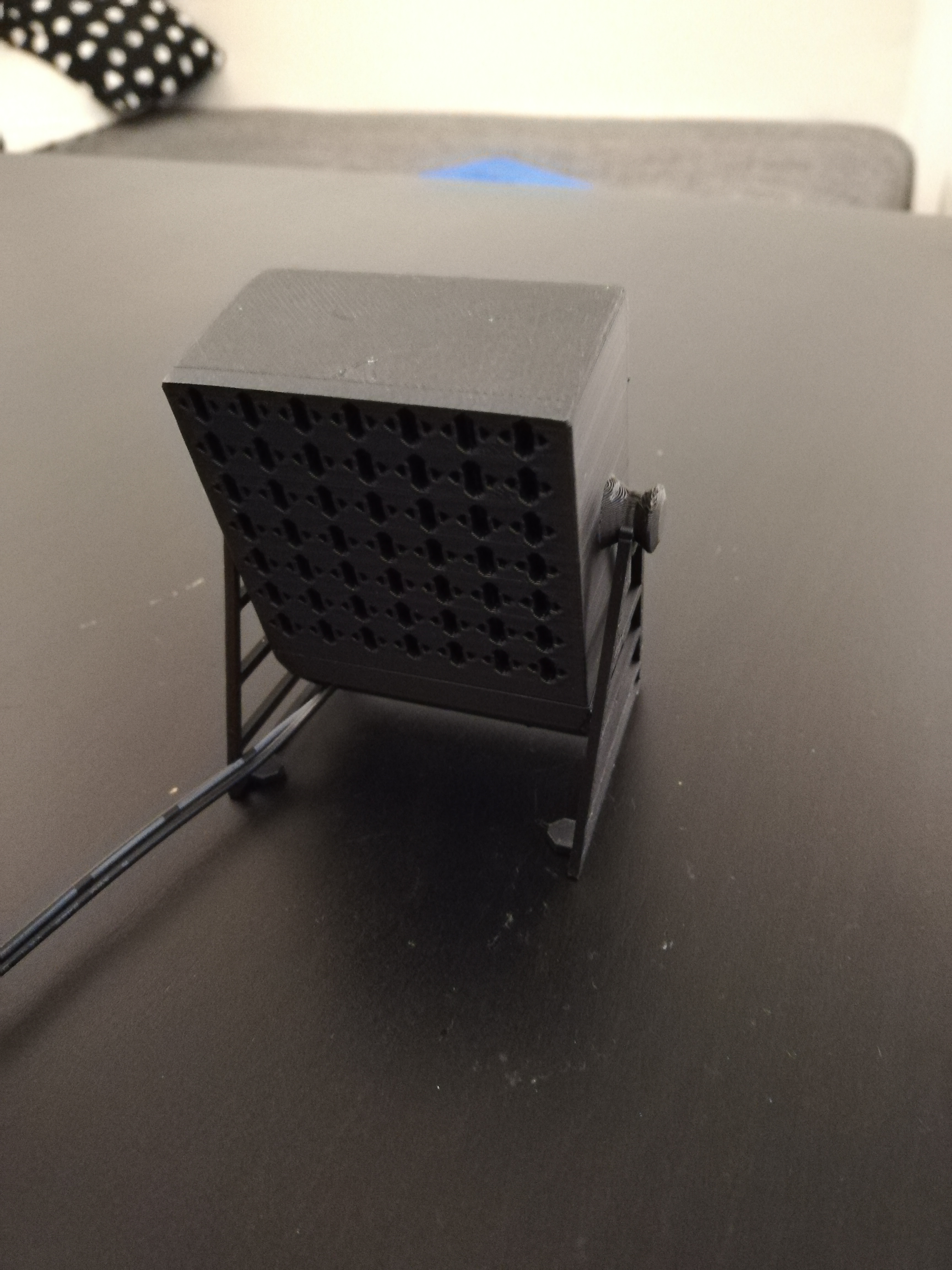
You will have several parts to print. The most important one is of the course the darth vader mask, casting the shadow. The other parts I designed, are meant to make the light source more adaptable and more discrete/beautiful. They are however not absolutely necessary.
- Vader
- Top light box
- Bottom light box
- Right foot
- Left foot
All parts are built for print withouth support (except a little for the main box). Watch out to slice the parts in the correct direction (see pictures).
Now concerning the light box, I designed some clips to secure both parts of the box in place. However, the print direction for the top part of the light box is so, that the mechanical constraint is applied between the layers (bending the part), leading to… breaking the part. The clips as they are break with the current print direction. To solve this I have two solutions:
- You either (like me) do not use the clips, since the print tolerances are quite tight, the base of the clips will fit in the gap of the counterpart and maintain enough pressure to keep both parts together quite reliably.
- Or you want some clips, and you change the print direction (leading to more support and general slightly worse print quality).
I recommend option 1. Print the parts as they are and try to fit them in (once everything is in place). If the clips break take them off the part, and put the parts together (they should hold unless your printer gives bad tolerances).
Building the Box
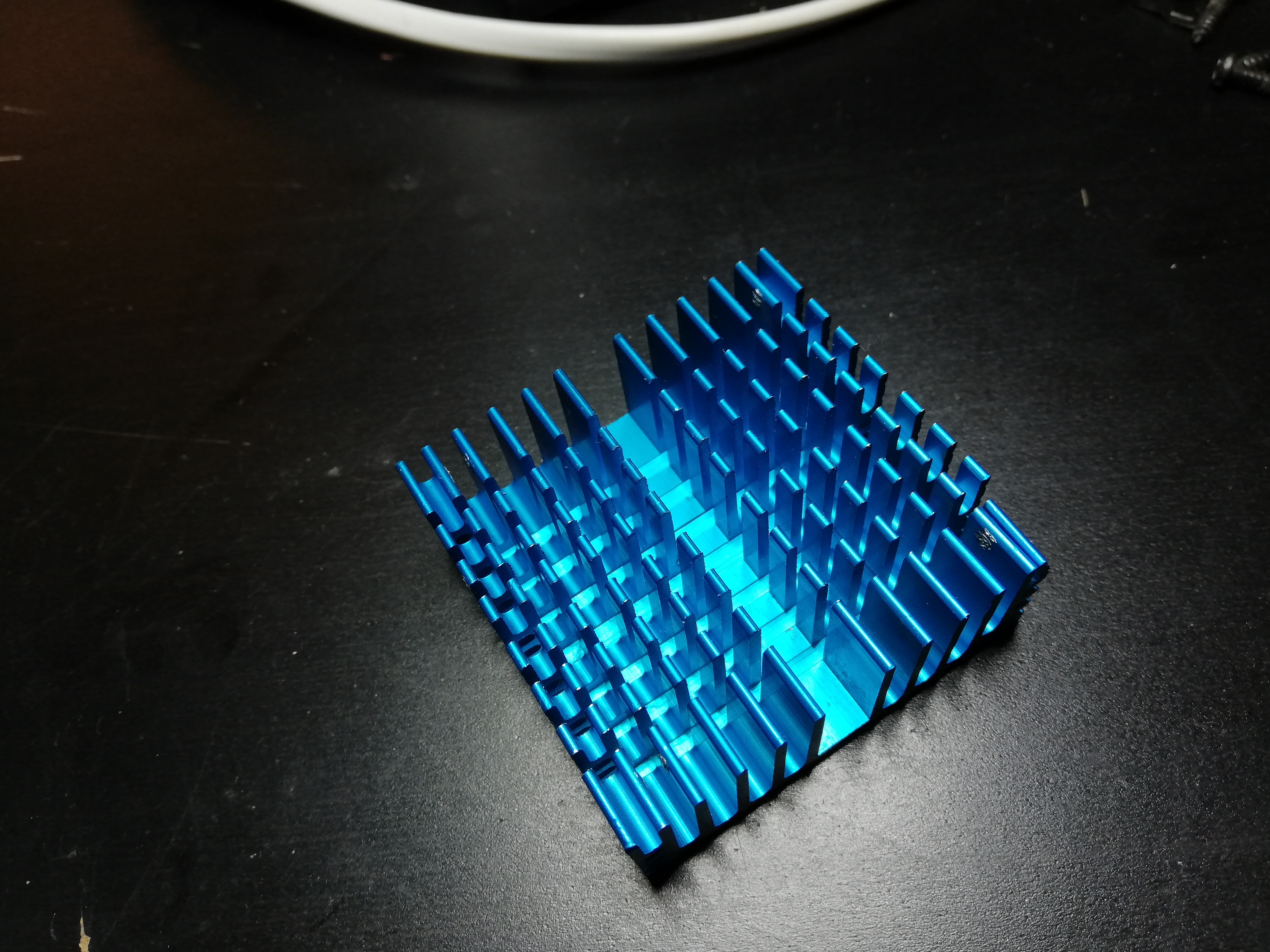
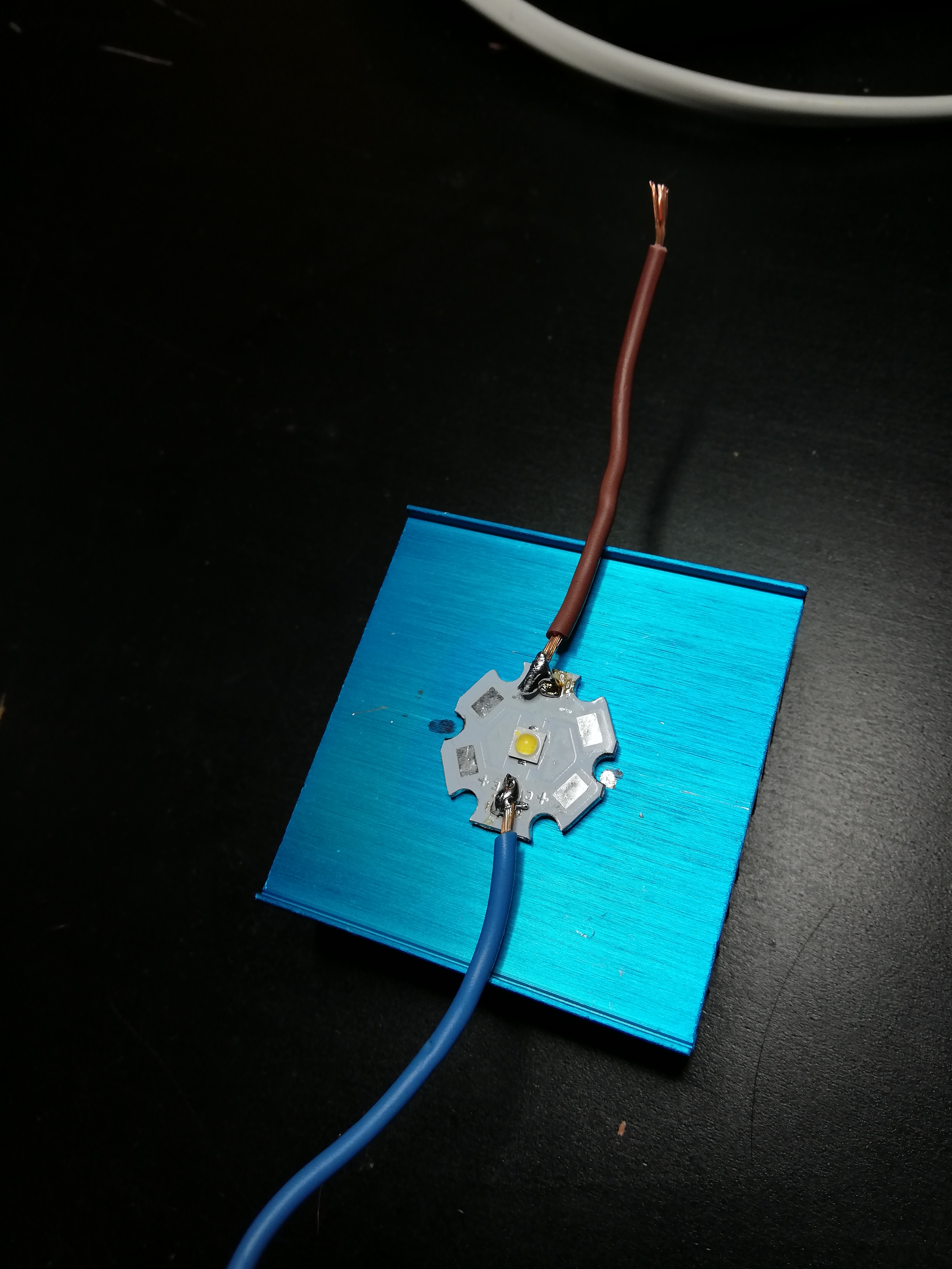
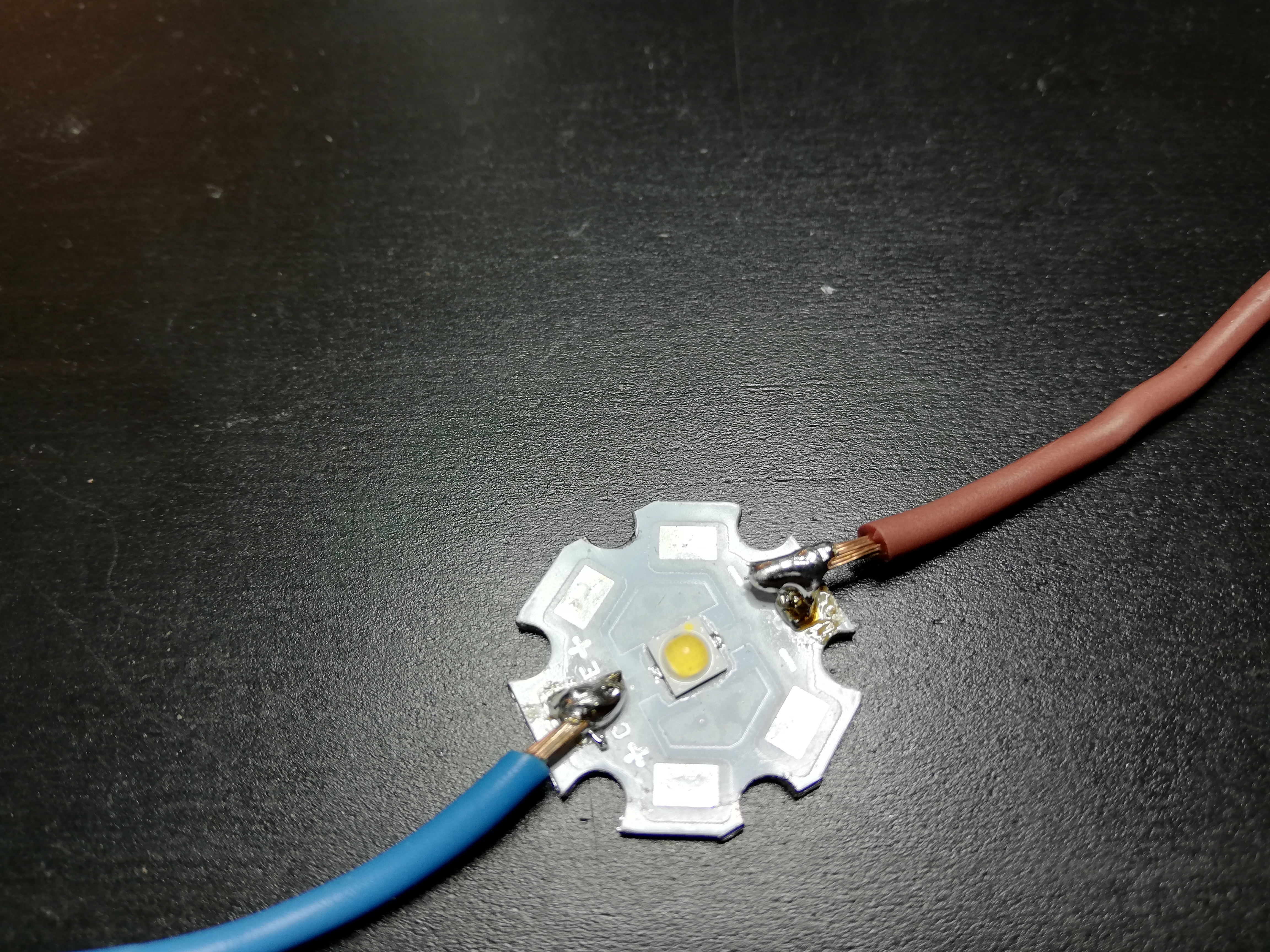
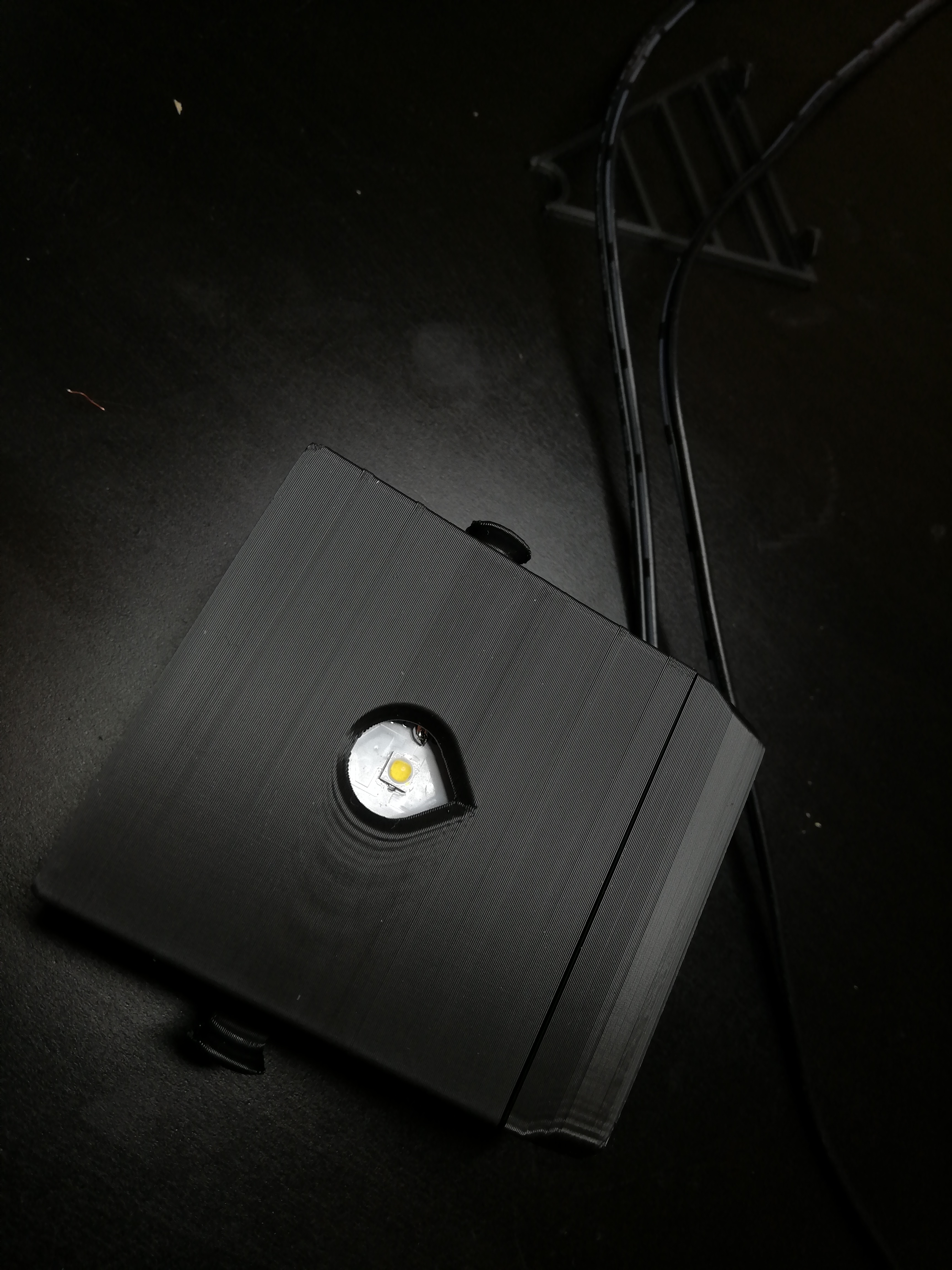
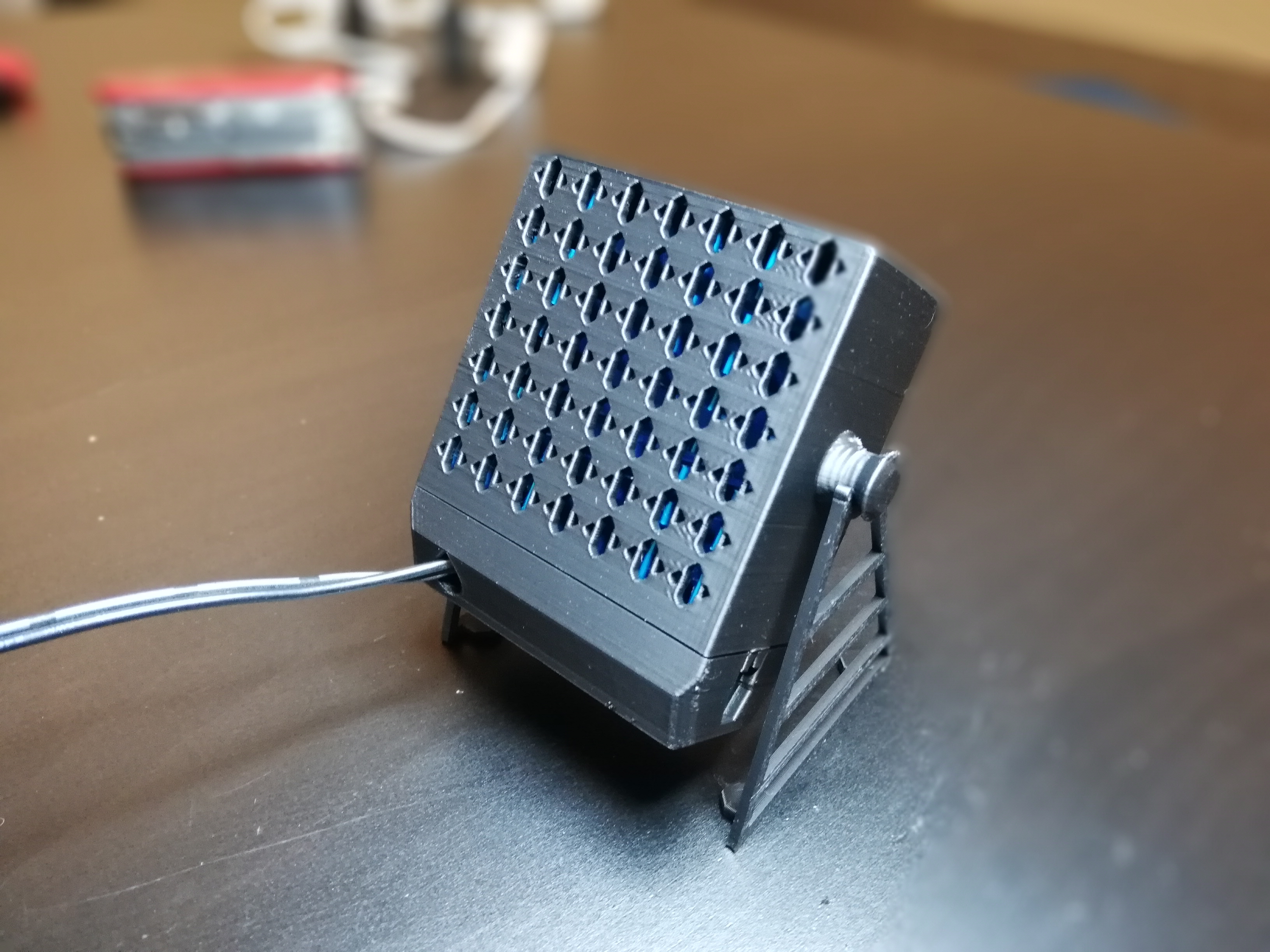
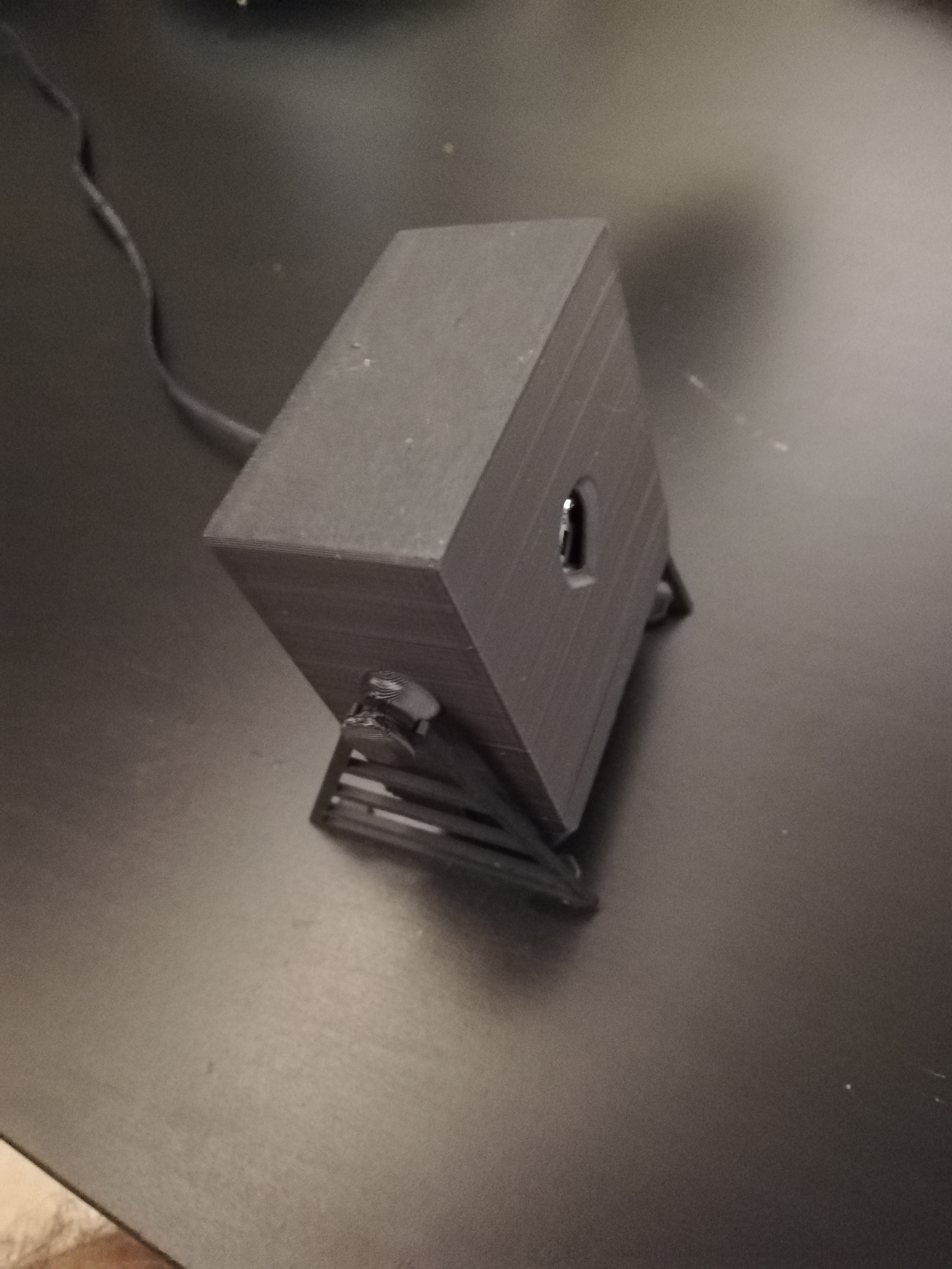
Now that you have everything, you are ready to build the light box. First, you will need to solder some wires to the LED.
WARNING!!! Do not secure the LED to the heat sink before soldering. If you do so you could have problem soldering on the LED, since the heat gets dragged in to the heat sink. So solder the LED first, then secure it on to the heat sink.
Depending on the LED you chose, choose your cable wisely. Do not have more than 4 Amps per square mm of cable. In my case the LED announces 700 mA, so 0,25 mm² should be enough.
Solder + and minus wires on to the pads of the LED (+ and – should be indicated).
Once this is done, you can secure the LED on to the heat sink. It is important to center the LED on the heat sink , or at least in front of the hole from the light box (in my case both light box and heat sink are centered, but if you have a slightly different heat sink, choose wisely the position of the LED).
Once you found the position of the holes, just draw them on the flat surface of the heat sink, and drill them (diameter depends on your bolts).
Then secure the LED on the heat sink with bolts and nuts.
Build in the electric switch if you have one.
Put the heat sink into the top part of the light box, making sure the LED faces the hole. Pass the naked cables from the power supply in the hole at the back of the bottom part of the light box, then connect them with for example domino electrical connector. You have a bit of spare space in the bottom part of the light box for hiding connectors/cables.
Close the box and put it on its feets.
Result
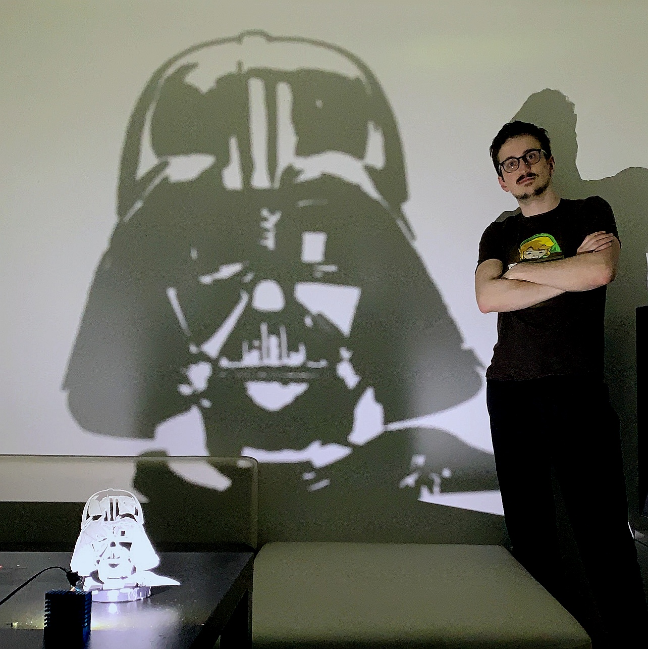
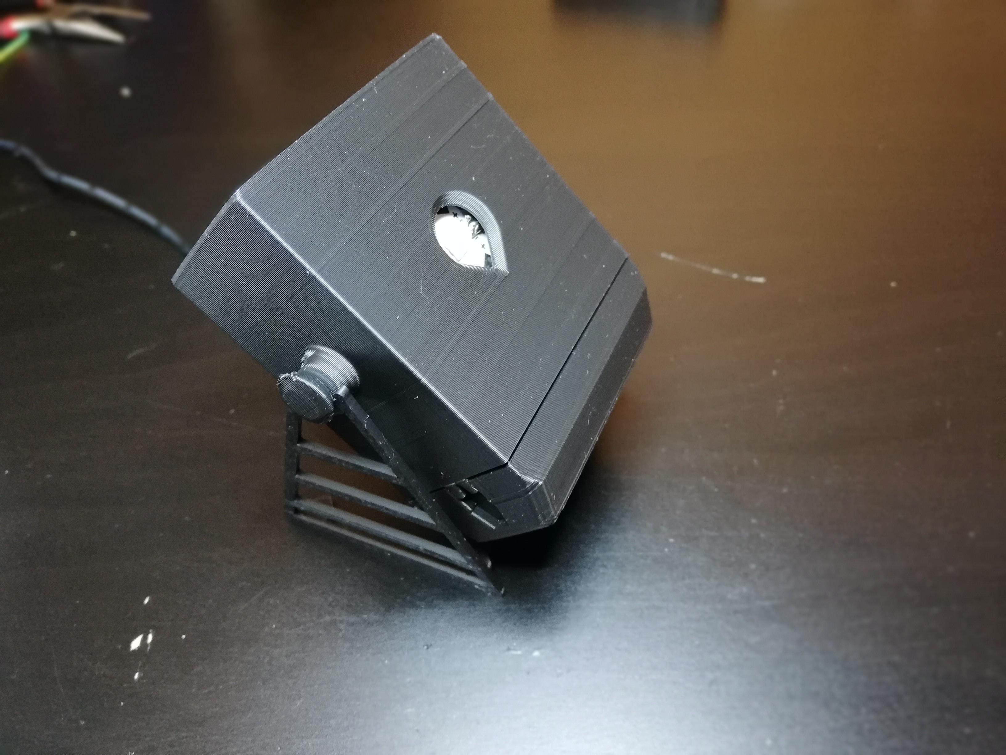
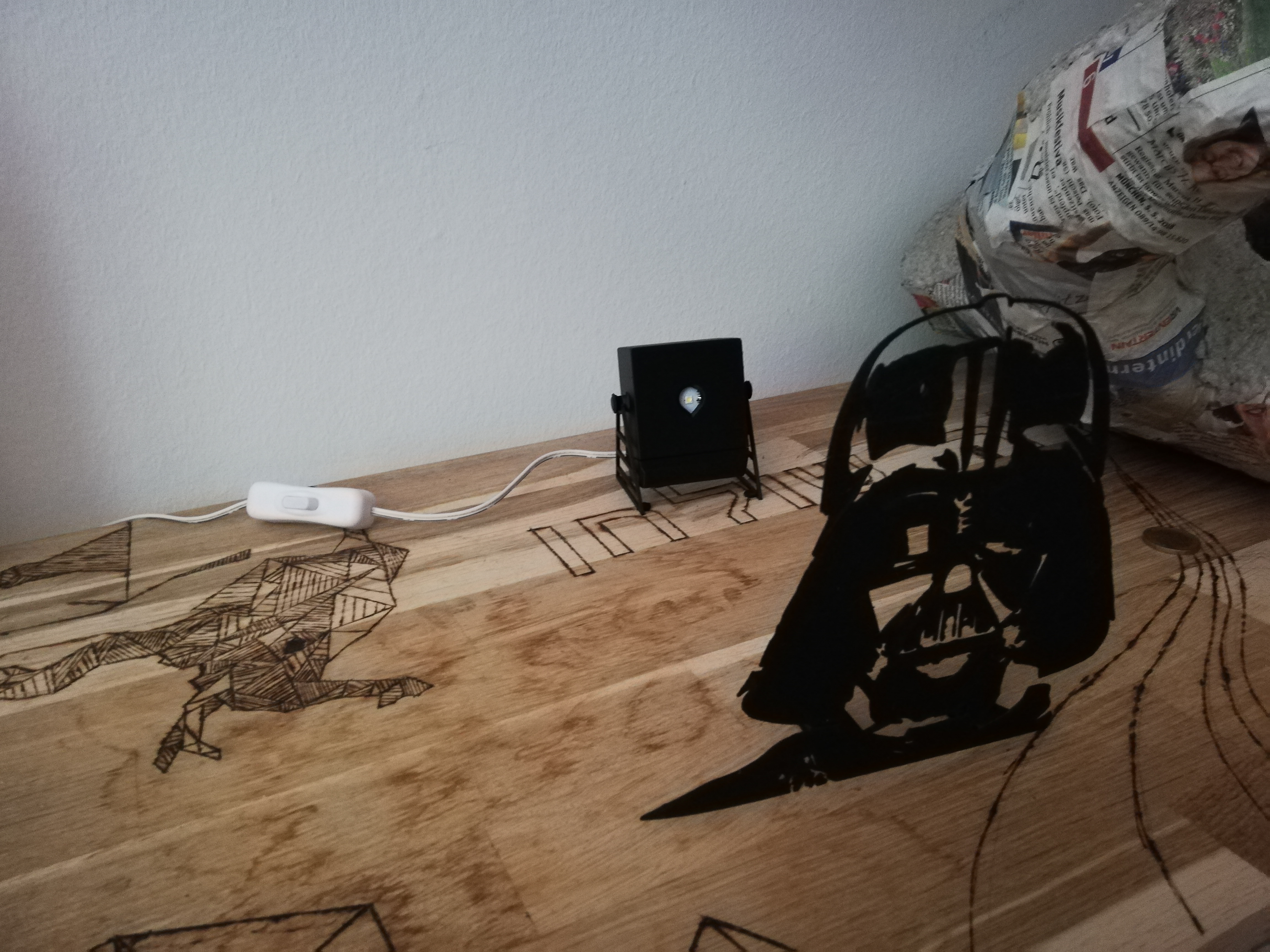
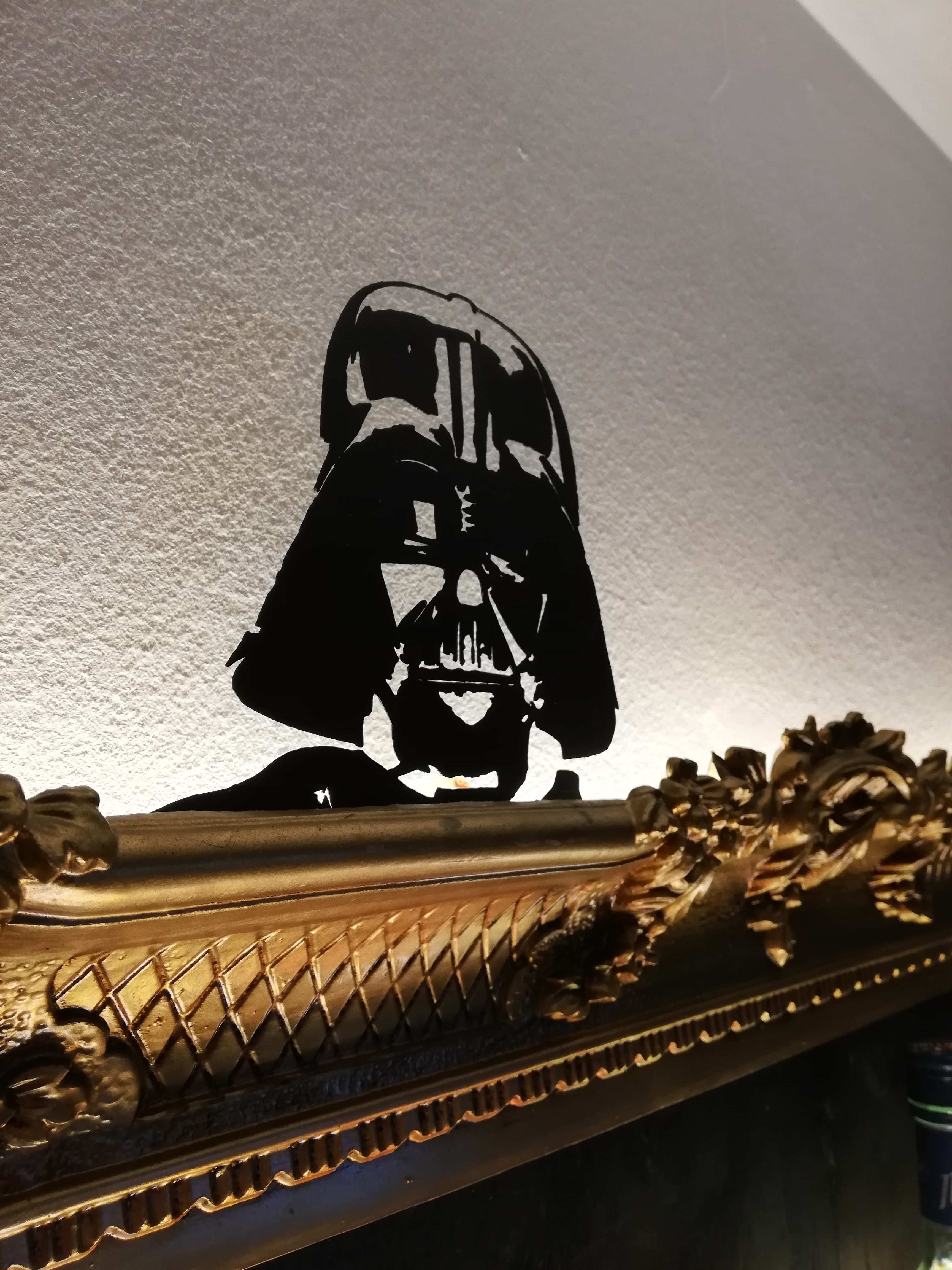
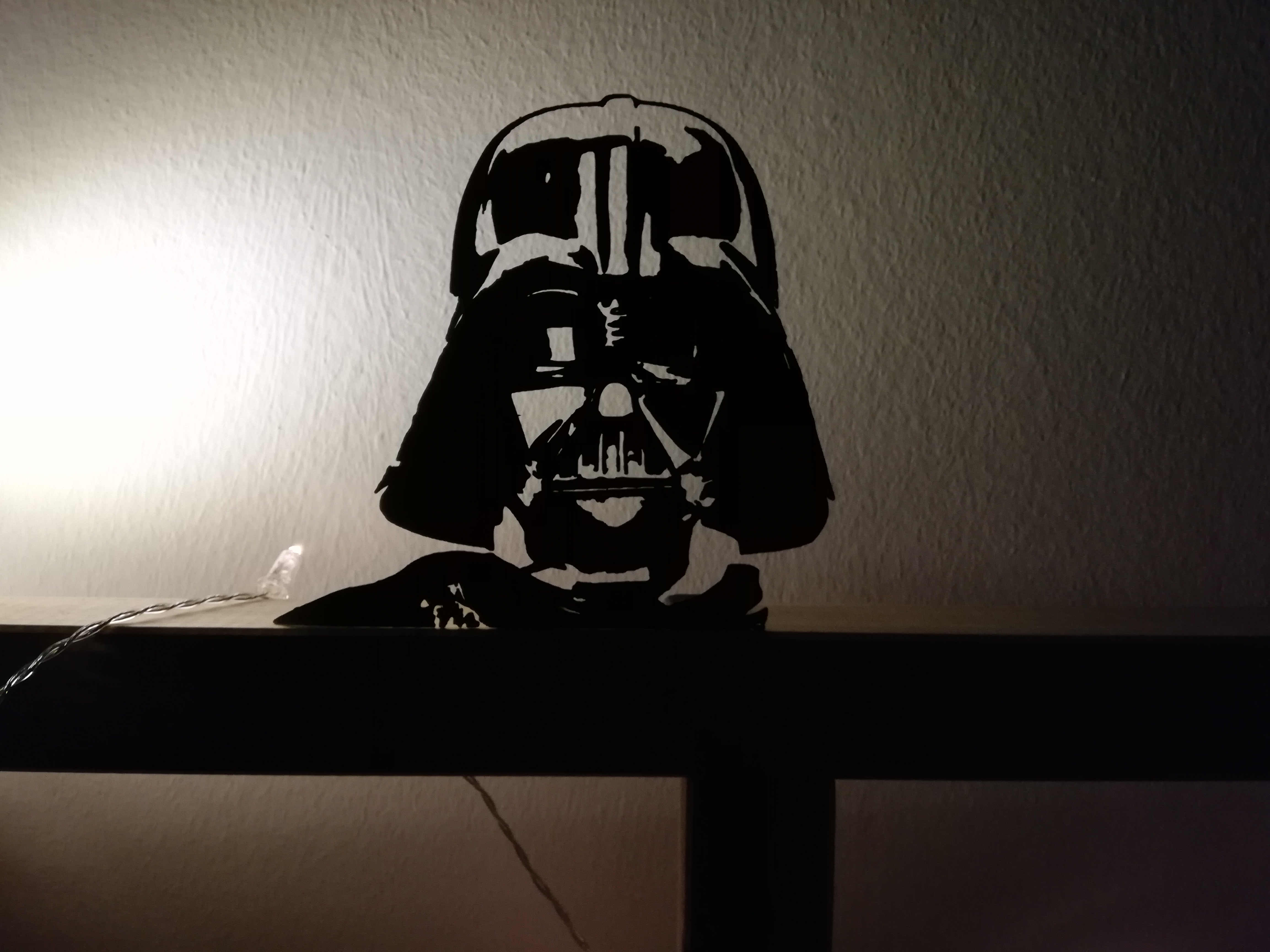
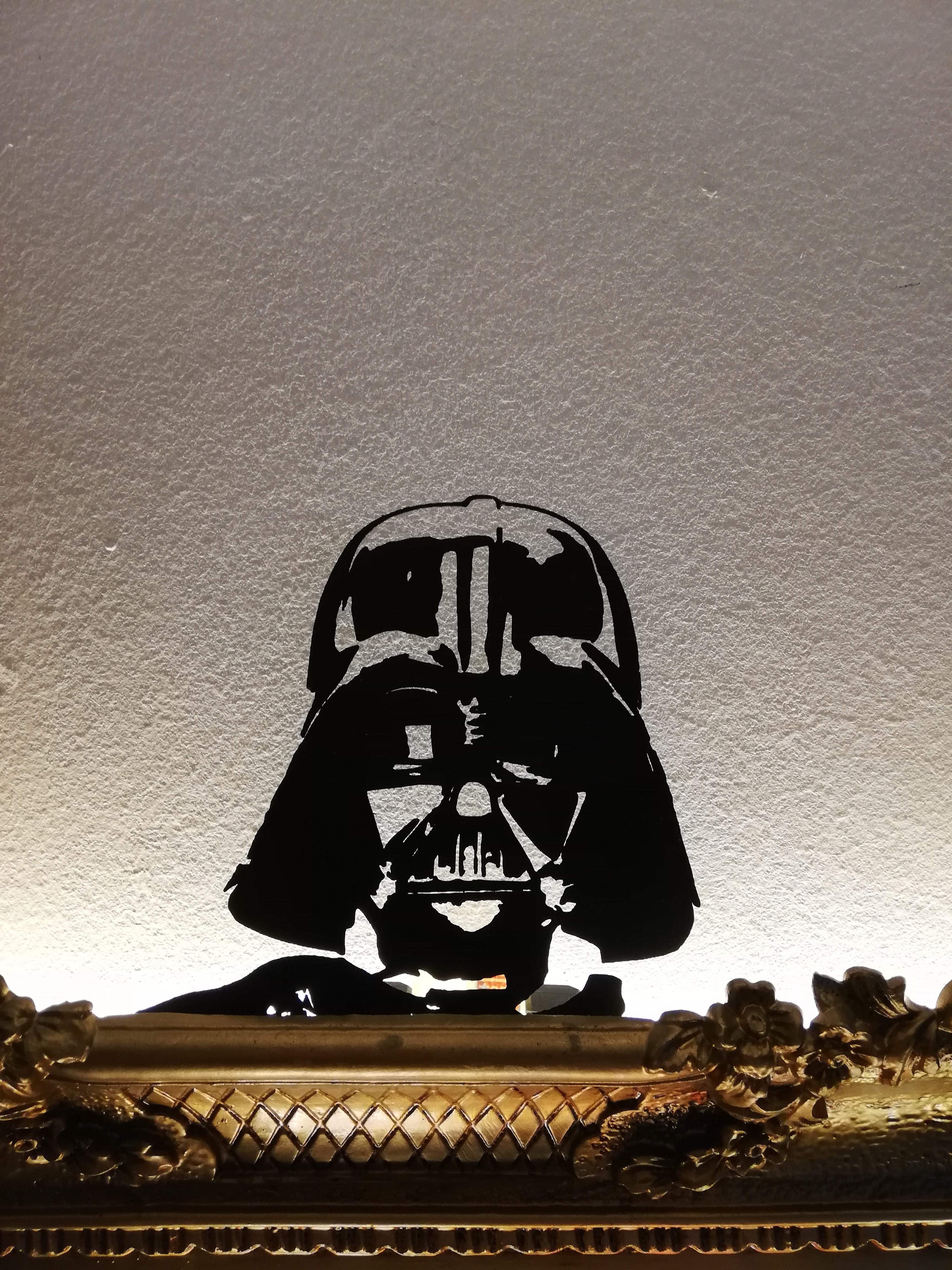
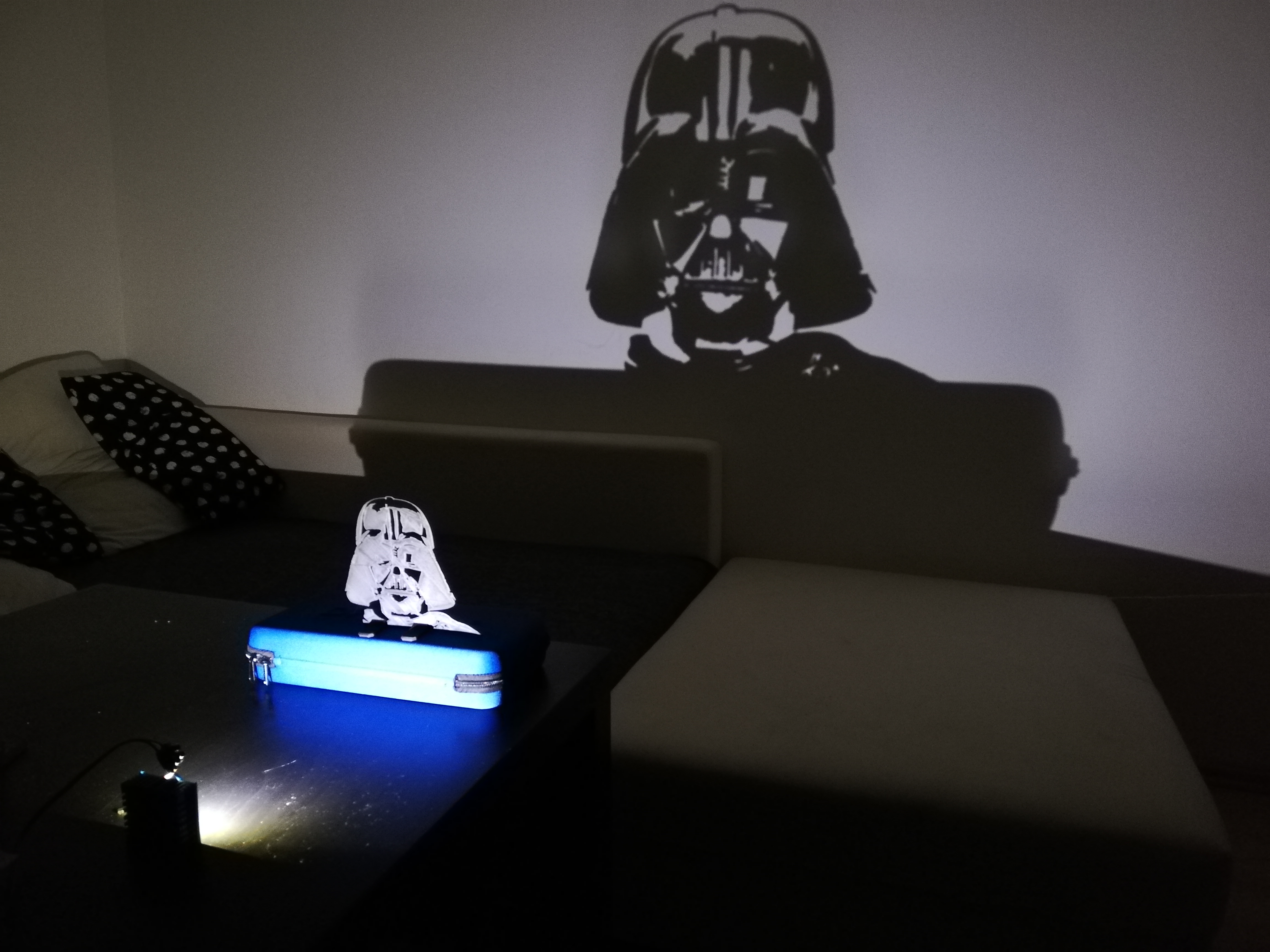
And Voila! Now you can cast the iconic shadow of darth vader everywhere you wish to.
You can also put the print in front of an illuminated surface (for example a wall with LEDs backlights) to put the vader in value (see pictures)