Dark Sensor -Arduino for Beginners
by Flameling01 in Circuits > Arduino
4705 Views, 37 Favorites, 0 Comments
Dark Sensor -Arduino for Beginners
Hi Guys,
This is my first instructable. It's something anyone can do and is a great first project.Please tell me how I could improve by commenting in the comments section. If you have any doubts Email me(Email ID:greatassassin123@gmail.com).
Please vote if you liked it.
This is my first instructable. It's something anyone can do and is a great first project.Please tell me how I could improve by commenting in the comments section. If you have any doubts Email me(Email ID:greatassassin123@gmail.com).
Please vote if you liked it.
Materials Required
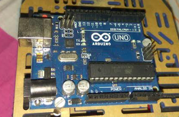

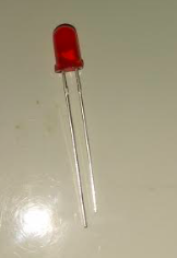
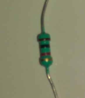
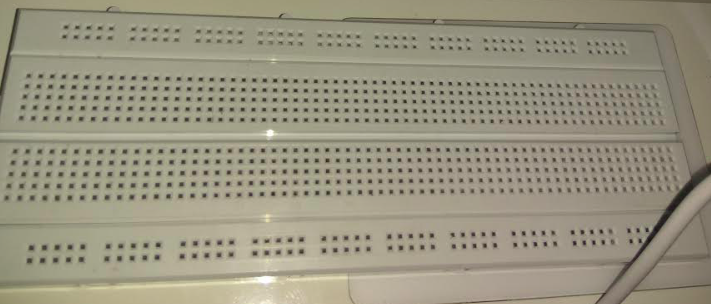

i)1*Arduino UNO
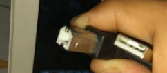
ii)1*USB A to B(Normally comes with Arduino board)
iii)1*Photoresistor(LDR)
iv)1*LED (Any Color)
v)1*1K ohm resistor
vi)1*Breadboard
vii)3*Male to Male Jumper wires or standard wires with both ends stripped
(Everything is available on amazon)
viii)A computer running Arduino IDE
ii)1*USB A to B(Normally comes with Arduino board)
iii)1*Photoresistor(LDR)
iv)1*LED (Any Color)
v)1*1K ohm resistor
vi)1*Breadboard
vii)3*Male to Male Jumper wires or standard wires with both ends stripped
(Everything is available on amazon)
viii)A computer running Arduino IDE
Building the Circuit
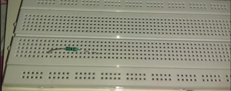
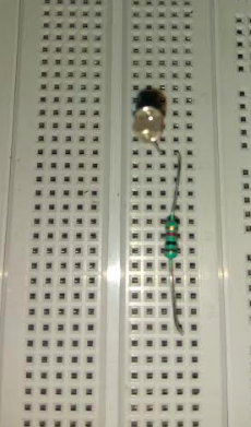
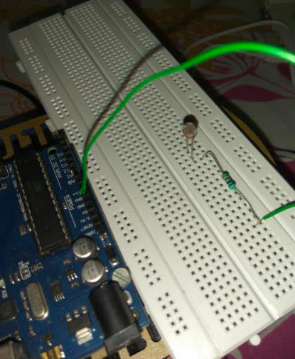
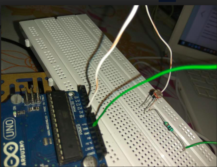
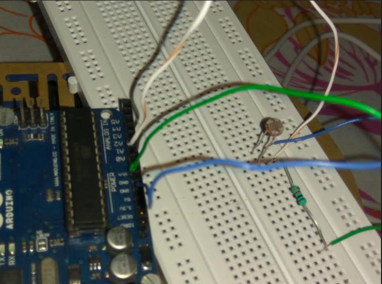
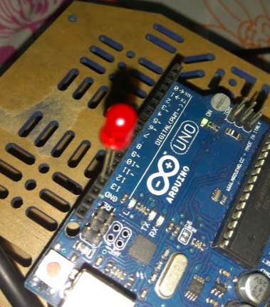
Lets get started for real!
1)Connect a resistor anywhere on one of the middle rows.
2)Connect the photoresistor in such a way that its one leg is in the same column as that of the resistor.
3)Connect a wire in the column of the lone resistor leg and put the loose end into the 'GND' port of the arduino board.
4)Connect a wire in the column which is common to both, the photoresistor and the 1K resistor and put the loose end into the analogue port 'A0'.
5)Connect another wire in the column of the lone photoresistor leg and put the loose end into the '5V' port.
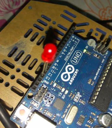
6)Put the longer leg of the LED into the '13' digital port and the short leg into the 'GND' port besides it.
Code
i)Connect the arduino board to your computer.
ii)Open Arduino IDE
iii)Choose the right port
iv)Copy and paste the contents of .txt file in the IDE.
ii)Open Arduino IDE
iii)Choose the right port
iv)Copy and paste the contents of .txt file in the IDE.
Downloads
Done!!!
