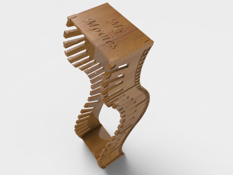
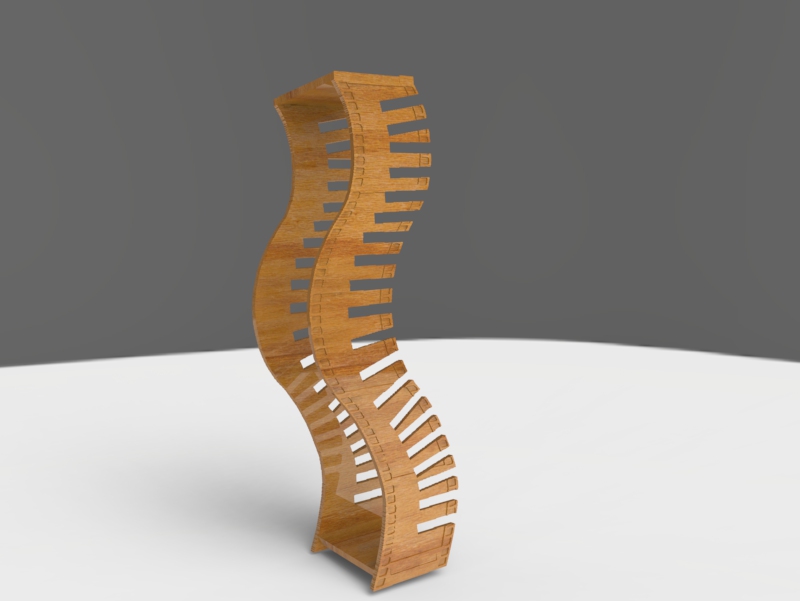
DVD Rack
Watch the Video
Creating the Side Panels Using an Image
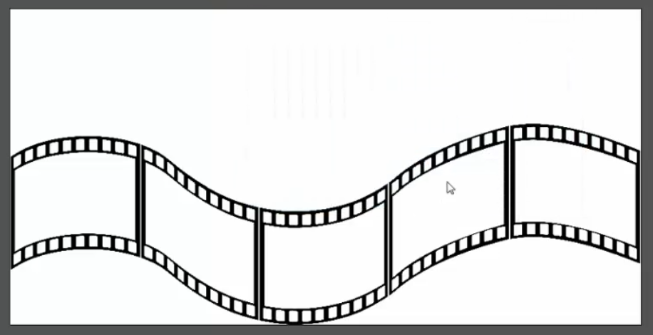
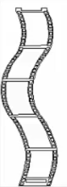
In order to get the movie reel pattern and shape for my design, I saved a clipart image found on the internet to my computer before starting.
If you are not using a saved image then select open New Model and create your own shape using the vector creation tools down the left sidebar and then skip to the Editing the Design section of these instructions.
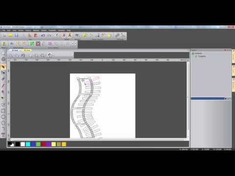
1. Open ArtCAM Express.
2. Click Open model in the left sidebar and select the saved image.
3. Set image size to have a length of around 700 mm. This will become the rough height of the DVD rack.
4. Use the Reduce Colours tool and input a maximum of 2 colours into the text box. This makes the bitmap easier to use. Set black as the primary colour by selecting it from the bottom toolbar.
5. Open the Bitmap to Vector tool and click Create Vectors. This will create boundaries around the bitmap outline which can be edited later.
6. Reduce the contrast of the bitmap using the slide bar above the model to see the created vectors more clearly and then with these vectors highlighted, press Ctrl + C on the keyboard to copy the vectors.
7. Close the model and open a new model with the following dimensions: 700 x 875 x 10 mm. Press Ctrl + V to paste the vectors into the new model.
Editing the Design
These vectors are going to become the side panel for the DVD rack and so need to be edited to allow assembly with the other parts.
1. Select the Node Editing tool and hover the cursor over the corner node of one of the segments. Press C on the
keyboard to cut the vector here. Do the same on the other corner of the vector and delete the line between the segments. Repeat this process for all the vectors separating the segments.
2. Select two of the outer vectors, right click and select Join Vectors then With a smooth curve. Repeat this until
all of the outer vectors are joined and then select Close vectors then With a smooth curve.
3. To create room for a slot into which the bottom panel will fit, use the Node Editing tool to cut a small portion of the sides of the large inside vector from the bottom segment, move the bottom line up and reattach it.
4. Create a rectangle with a height of 10 mm and width of 80 mm and reposition at the centre of the gap which was just created.
5. Create a new rectangle with height 10mm and width 22 mm and position it just above the left corner of the outer vector. Holding Ctrl and Alt, click and drag the rectangle to create a copy above the top right corner of the outer vector. Check the size of the gap is just above 80 mm by creating a rectangle, then delete this
rectangle.
6. Use Node Editing again to join these two rectangles to the outer vector and close the vector by moving end points.
7. Click and drag the cursor to highlight all of the vectors and then holding Shift on the keyboard, deselect the outer vector and the new slot vector and Group the rest together.
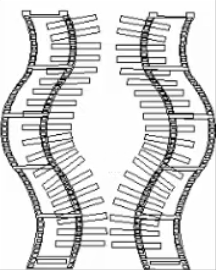
8. Create a rectangle with height 15 mm and width 135 mm, this is just larger than a typical DVD casing. Cut the right side of the outer vector near the top and bottom. Select first the rectangle, then the side vector and open the Paste Along a Curve tool. Input 20 copies and click Paste.
If necessary, undo and alter the orientation of the rectangle and the number of copies until the paste looks right.
9. Delete the rectangle used to create the paste, reattach the side of the outer vector and Ungroup the slot vectors created. Use the Transform tool to rotate each of the slots that is pointing downwards to be horizontal. This is to stop the DVDs from slipping out of the slots.
10. Group these slot vectors together by clicking and dragging the cursor and selecting Group.
11. With all the vectors highlighted, open the Mirror tool. Ensure that only the Copy original objects tick box is selected and then click Right. Adjust the positioning of the mirrored vectors to create a gap between the two
panels.
Top and Bottom
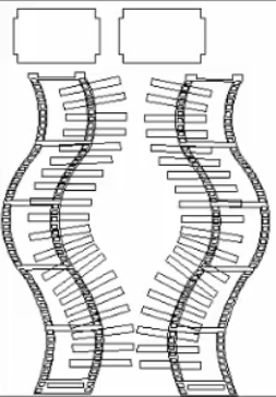
1. Create a rectangle with height 120 mm and width 190 mm and then another rectangle over the top with height 140 mm and width 210 mm and snap the centre points of each together.
2. Use the Trim tool within the Vector Creation ribbon and trim each of the inside vectors leaving just an outline
vector.
3. As before, highlight two of the vectors, right click and join them together. Repeat this until the vector is closed.
4. Copy this vector into an empty space in the material.
5. If desired, text can also be added to the top part using the Text tool.
Toolpaths
1. Select Toolpaths from the Project tree.
2. Select Create Profile Toolpath and highlight the outer vectors of the side panels and the top and bottom parts. Ensure that the toolpath is set to machine Outside the Selected Vectors. Select a tool (12 mm end mill) and click Calculate Now. This should generate a red line around the outside of each of the outer vectors which shows toolpath. This can be hidden using the light bulb icons in the Toolpath branch of the Project tree.
3. Again select Create Profile Toolpath and select the slot vectors including the ones near the bottom of each side panel. Change the profile to Inside, select a smaller tool (5 mm end mill) and press Calculate Now.
4. Select the inner pattern vectors which were grouped earlier and select the Create Area Clearance Toolpath. Set a start depth of 0 mm and end depth of 2 mm and select a tool to machine with (5 mm end mill). Choose a machining strategy and click Calculate Now.
5. If you create text on the top part, highlight this vector and select Create V-Bit Carving Toolpath. Select a start depth of 0 mm and select one of the small v-bit carving tools. Click Calculate Now.
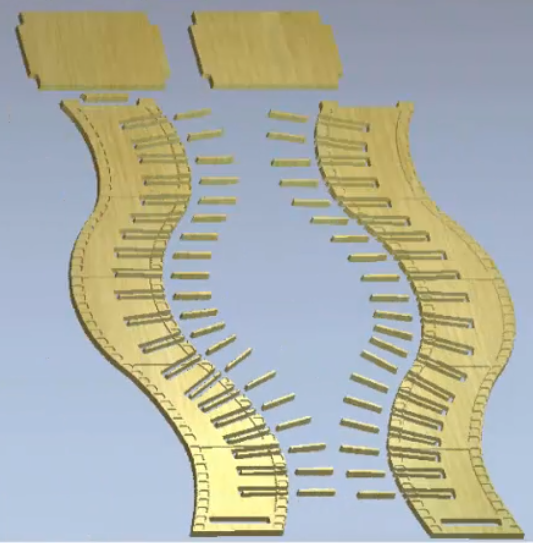
6. Right click on Toolpaths in the project tree and select Simulate All Toolpaths. This will run a simulation of the toolpaths created, showing a preview of the machined material. The waste material can be automatically or manually deleted within the simulation toolbar and the material of the simulation can be changed.
7. When satisfied with the simulation, select Save Toolpaths in the Toolpath toolbar and select a file format suitable for the CNC machine that you intend to use. The toolpaths can be saved separately by selecting the tick box on the left.
8. These toolpaths can now be imported to the machine and the parts can be machined. A little sanding, varnishing and gluing could be applied if necessary and then the rack can be easily assembled
together.