DOSX Portable: Learn, Emulate, and Explore X86 on ESP32 Hardware
by czwienczek in Circuits > Computers
2017 Views, 13 Favorites, 0 Comments
DOSX Portable: Learn, Emulate, and Explore X86 on ESP32 Hardware


As an electrical engineer specializing in hardware and with a strong background in physical systems, I've always been fascinated by what goes on behind the scenes in computing. But my journey into the software world has been entirely self-taught: a path driven by curiosity, persistence, and a desire to truly understand how things work at the most basic level.
For years, I wanted to understand how an operating system actually works: how to simulate it, how to build its kernel from scratch, and how technologies like VirtualBox or VMware manage to virtualize entire machines. I imagined being able to modify interrupts, create custom commands, or even design a high-speed control interface compatible with OT systems. What if I could tweak FreeDOS or WinMOS to access independent memory blocks through hardware and run legacy SCADA, RTU, or Siemens PLC software from the 1980s and 1990s—software that once powered industrial systems seamlessly? What if I could create a graphical user interface to visualize and control that data in real time?
Books gave me a lot of theory, but it was often too abstract and overwhelming. So I took a different path: I immersed myself in real-world code. I started reading C and C++ libraries that were meant to emulate hardware, analyzing their operation and, little by little, building a mental map of how these systems were structured. That's when it all started to make sense.
At some point in all this research, I realized that to create a truly backwards compatible environment, I needed to emulate not only the CPU, but also the chips that made those systems work (it was logical!!!) yes it was logical but "Wiring components in software" creating libraries of these chips is what really got the idea in me, probably a software engineer will know it in his training, but understanding it and "touching" it was what modified my design paradigm and understanding the FABGL, prebri86, fake86, spectrum libraries... The key: it involves replicating the behavior of components such as the PIC8259A (programmable interrupt controller), the PIT8253 (programmable interval timer), the 8042 keyboard controller, the RTC (MC146818), the serial ports (COM1/COM2), the CGA/Hercules video adapters and even GPIO expanders like the MCP23S17, understanding how to create a "bus" like create the "FAT16" base on an emulated SD card. Once I understood all of this, how these libraries worked, I had those elements ready—ta-da!—I had a fully emulated hardware environment capable of running real DOS-based software like FreeDOS, WinMOS, and even early versions of Windows. It wasn't just a simulation anymore; it was a functional, software-defined retro machine.
I explored platforms like the ESP32, Raspberry Pi Pico, and others, but the ESP32 stood out: powerful, flexible, affordable, and with a dynamic ecosystem. I began experimenting with libraries like FabGL, TVC-ESP32, and ESP32-8Bit—excellent starting points, although their internal documentation was limited. That limitation prompted me to delve deeper into the source code, where I began to understand how to modify and extend its functionality.
From there, I discovered other fascinating projects: pebri86, ESPectrum, ESP32TinyGalaksija, ODROID, and more. Each one opened a new window into retro computing and embedded emulation. This project was born from that journey: not just from the desire to make things work, but to understand why and how they work. And yes, perhaps also to indulge in a bit of retro hobbyism along the way.
Hardware/Components and Architecture
Emulated CPU: ESP32 (Xtensa LX6 dual-core, 240 MHz, 520 KB SRAM) with x86 emulation via adapted FabGL project, optimized for FreeDOS.
Operating System: FreeDOS with support for multiple retro applications and DOS-based development tools. Supports multiple FAT16 partitions on a microSD card.
Input Interface (Keyboard/Mouse): RP2040 as USB HID controller for keyboard and mouse, acting as a virtual USB Hub. Communication between RP2040 and ESP32 via adapted PS2 interface configured for FreeDOS (https://github.com/No0ne/ps2x2pico).
Video Output: 7’’ HDMI screen with a cost-effective video controller (AD9983AK by Analog Devices). Supported resolution: up to 640x480 for the first version.
Storage: microSD with FAT16 file system, mounted as the main drive for FreeDOS and Windows 3.0. Supports multiple disk images and swap.
Expansion Ports: RS-232 TTL serial port for compatibility with retro hardware and embedded projects. Expandable with I2C/SPI modules for sensors or actuators.
Printing: Serial printer connected via Chinese Bluetooth SPP (Serial Port Profile). Supports ESC/P and PCL commands for direct printing from DOS. Currently working on a freedos driver that sends data to a memory block that the ESP32 captures and translates to Bluetoothd (a COM1/freedos printer --> Bluetooth output).
Supplies


To avoid creating empty links or unique shopping lists, I'll clearly state the specifications so you can find them on AliExpress, Badui, Mouser, Farnell, or Amazon.
- ESP32x38 WROOM Espressif ESP32-WROOM-32 WiFi + BT, Dual-core Xtensa LX6, 240 MHz, 520 KB SRAM ESP32 3.25
- Adaptador VGA a HDMI FOINNEX VGA macho a HDMI hembra, 1080p, con audio Conversor integrado (no especificado) 9.70
- Adaptador HDMI macho-macho Elecrow HDMI tipo A doble macho, 1080p - 1.59
- Pantalla táctil 7" HDMI Genérica / LESOWN 1024x600, IPS, táctil capacitiva 5 puntos, HDMI Controlador táctil GT911 o similar 17.00
- Cargador 3.7V 18650 TP4056 (genérico) Entrada 5V, salida 4.2V, protección sobrecarga TP4056 1.53
- Amplificador 2x3W PAM8403 Clase D, 2.5–5V, eficiencia >90% PAM8403 0.89
- Baterías 18650 (x3) Genéricas 3.7V, 2600–3500 mAh, Li-ion - 4.50 (1.5 x 3)
- Caja porta baterías (x3) Genérica Para 1 batería 18650, con cable - 4.62 (1.54 x 3)
- Teclado USB mini Genérico USB, compacto, 83–88 teclas - 6.00
- Raspberry Pi Pico W Raspberry Pi Dual-core ARM Cortex-M0+, 133 MHz, 264 KB SRAM, WiFi RP2040 1.79
- HUB USB 4 puertos Genérico USB 2.0, 4 puertos, alimentación por USB Chip GL850G o similar 1.39
- Conversor de nivel lógico I2C Genérico 4 canales, bidireccional, 3.3V ↔ 5V BSS138 + resistencias pull-up 0.45
- Módulo lector microSD SPI Genérico Interfaz SPI, 5V/3.3V compatible AMS1117 + adaptador SPI 0.80
Costo total 53,11€
What Is FabGL?

FabGL (http://www.fabglib.org) is a graphics and emulation library developed specifically for the ESP32. Its main purpose is to allow this microcontroller to behave like a complete retro computer, including video output, keyboard input, sound, file system access, and more. While it was initially designed to emulate terminals like the VT100 or run retro games, it has since evolved to include a functional x86 emulator, capable of running FreeDOS and similar platforms. There is some information about this library, but I couldn't find much that tells me how it was conceived. Remember, this was the goal, to understand how things work. Just as it served me a lot as a guide to other designs and assemblies in the following links:
https://land-boards.com/blwiki/index.php?title=RetroComputers
Provide a very basic idea of how this library works on the ESP32.
User (FreeDOS running apps)
- The user interacts with the system as if it were a real PC.
- They can run DOS programs, games, utilities, etc.
- Input is handled via keyboard (PS/2 or USB), and output is displayed on a VGA or HDMI screen.
i8086 Emulator (C++ Virtual CPU)
- FabGL includes a 16-bit x86 CPU emulator, written in C++.
- This emulator interprets x86 instructions (like MOV, INT, JMP, etc.).
- It supports real mode, allowing systems like FreeDOS to run.
- It handles interrupts (INT 10h, INT 13h, etc.) and BIOS calls.
This is where FabGL shines by emulating the essential components of a classic PC:
Emulated Subcomponents:
- BIOS:
- Implemented in C++, it handles basic interrupts like video (INT 10h), disk (INT 13h), keyboard (INT 16h), etc.
- Allows FreeDOS to function as if it were running on real hardware.
- RAM (s_memory):
- FabGL reserves memory blocks to simulate system RAM.
- The emulator accesses this memory just like a real CPU would.
- I/O Ports:
- Input/output ports (in, out) are emulated to interact with virtual peripherals.
Emulated Peripheral Chips:
- PIT8253 (Timer):
- Emulates the programmable interval timer to generate periodic interrupts (e.g., for system clock or speaker tones).
- PIC8259 (IRQ Controller):
- Handles simulated hardware interrupts (keyboard, timer, etc.).
- CGA/HGC (Video):
- Emulates classic video adapters.
- FabGL generates real VGA signals using the ESP32’s DAC, allowing output to physical monitors.
- 8042 (Keyboard Controller):
- Emulates the PS/2 keyboard controller.
- Can receive input from a physical keyboard connected to the ESP32 or from a USB HID device via RP2040.
- COM1/COM2 (Serial Ports):
- Emulates serial ports for communication with external devices or debugging.
- RTC (MC146818):
- Emulates the real-time clock, allowing FreeDOS to keep system time.
- MCP23S17 (GPIO Expander):
- While not part of FabGL directly, it can be integrated to expand I/O ports for custom projects.
ESP32 (Real Hardware + FabGL)
- The ESP32 runs the entire system:
- Xtensa LX6 dual-core CPU at 240 MHz.
- Uses PSRAM and internal SRAM to handle video, sound, and emulation.
- Generates VGA signals, handles keyboard input, PWM audio output, microSD access, and more.
- FabGL leverages the ESP32’s peripherals to simulate a complete PC without needing additional hardware.
Key Library:
- fabgl::VGAController: generates VGA signals.
- fabgl::PS2Controller: manages keyboard and mouse input.
- fabgl::SoundGenerator: produces basic audio (beeper, tones).
- fabgl::Terminal: emulates terminals like VT100.
- fabgl::x86emu: the core x86 emulator (based on adapted open-source emulators).
- fabgl::FileBrowser and fabgl::FileSystem: enable file access from microSD.
Hardware


Below, I'll try to explain the hardware and summarize all the information I gathered, including the most interesting and important information. The first uses Uses the ESP32 DevKit ESP32-WROOM The following page uses ESP32-DevKitC-Vxx (ESP32-WROVER). The difference between Wroom and Wrover is simply the existence or not of PSRAM..The information was obtained from several links, but the most interesting were a Japanese one and this wiki:
The first link explains the hardware at the utility level and how simulations work, as well as how to adjust resistors using LTSPICE, which I found to be excellent and a very useful contribution.
https://land-boards.com/blwiki/index.php?title=ESP32-VGA
(I have taken some images from this page because I found them interesting and very educational.)
The second page, in Japanese, was the "holy grail" of solutions to problems using a wroom ESP chip. I'll try to summarize the page, but above all, I appreciate all the accurate and specific information, especially regarding updating certain libraries and how FABGL can work on a wroom (without PSRAM, as in the commercial FABGL ITT module).
https://ht-deko.com/arduino/fabgl.html
Summary and overview of the DOX project (DOScitoX).
ESP32 DevKit with ESP32-WROOM
- Main module: ESP32-WROOM-32
- RAM: ~520 KB internal SRAM
- Flash: Typically 4 MB
- PSRAM: No external PSRAM
- Typical use: General IoT projects, sensors, automation, etc.
- Advantage: Low cost, widely available, ideal for lightweight applications.
ESP32-DevKitC-Vxx with ESP32-WROVER
- Main module: ESP32-WROVER
- RAM: 520 KB internal SRAM + 4 MB (or more) external PSRAM
- Flash: 4 MB or 8 MB (depending on the version)
- PSRAM: Includes external PSRAM (great for graphics, emulation, large buffers)
- Typical use: More demanding applications like emulation, image processing, audio, etc.
- Advantage: Much more memory for running complex systems like FabGL, FreeDOS, etc.
Which one should you choose for your DOSX project?
For x86 emulation with FabGL, FreeDOS, and VGA graphics, the ESP32-WROVER (with PSRAM) is highly recommended. The extra PSRAM allows you to:
- Load larger disk images
- Run more complex DOS programs
- Use higher video resolutions
- Handle multiple video/audio buffers efficiently
Why I Used the ESP32-WROOM in This Project
Although the ESP32-WROVER offers more memory thanks to its external PSRAM, I deliberately chose the ESP32-WROOM for this project to demonstrate that a functional x86 emulation environment can be built even on limited hardware—and to keep the platform accessible, affordable, and replicable.
The WROOM module is widely available, cost-effective, and supported by a massive ecosystem. By optimizing memory usage and carefully managing resources, I was able to run FreeDOS, emulate key hardware components, and interact with peripherals—all within the constraints of the WROOM’s internal SRAM.
This choice reflects one of the core goals of the project:To show that retro computing and system-level learning can be achieved with minimal hardware, encouraging experimentation and deeper understanding.
Additionally, using WROOM:
- Keeps the hardware footprint small and power-efficient.
- Makes the project more approachable for students, hobbyists, and educators.
- Challenges the developer (me!) to write more efficient, modular, and optimized code.
Of course, the project is scalable—those who want to run heavier applications or higher-resolution graphics can easily port it to a WROVER module. But starting with WROOM proves that you don’t need maximum specs to build something meaningful and educational.
Main Controller: ESP32 WROOM-32
- Dual-core Xtensa LX6 microcontroller @ 240 MHz
- 520 KB SRAM, WiFi + Bluetooth
- Powered by 5V via TP4056 module
Video Output (VGA to HDMI)
See pictures about selecction:
- VGA GPIOs:
- HSync: GPIO23
- VSync: GPIO15
- R0: GPIO22, R1: GPIO21
- G0: GPIO19, G1: GPIO18
- B0: GPIO5, B1: GPIO4
- Conversion Path:
- VGA output → DAC via resistors (422Ω and 845Ω) → FOINNEX VGA to HDMI adapter → 7" HDMI display
- Display: 1024x600 resolution, non-touch
Audio
- Output Pin: GPIO25
- Path: Low-pass filter → PAM8403 amplifier → Speaker
User Input (USB Keyboard and Mouse)
- USB HUB connects keyboard and mouse
- Raspberry Pi Pico converts USB to PS/2
- PS/2 Inputs to ESP32:
- Keyboard: KBDAT (GPIO32), KBCLK (GPIO33)
- Mouse: MSEDAT (GPIO27), MSECLK (GPIO26)
Storage
- MicroSD via SPI:
- MOSI: GPIO17
- MISO: GPIO16
- CLK: GPIO14
- CS: GPIO13
Serial Communication
- COM1: RX (GPIO3), TX (GPIO1)
- COM2: RX2 (GPIO34), TX2 (GPIO2)
- Both connected to FTDI modules for RS232 output
Power System
- 3x 18650 Batteries (3.7V, 3300mAh each) in parallel → 9900mAh total
- TP4056 Module:
- Input: 5V USB
- Output: Regulated 4.2V
- Includes overcharge and discharge protection
- Power Distribution: Feeds ESP32, display, amplifier, USB hub, and peripherals
Estimated System Runtime
- Total Capacity: 3300 mAh (3.3 Ah)
- Estimated Consumption:
- ESP32: 80 mA
- HDMI Display: 400 mA
- Audio (PAM8403): 150 mA
- USB HUB: 100 mA
- Peripherals (keyboard, mouse, SD): 200 mA
- Total aprox: 930 mA
- Estimated Runtime: 3.3Ah/ 1A = 1.3 hours.
Main Controller: ESP32 WROOM-32 (38 pins)
This microcontroller is the core of the system. It features a dual-core Xtensa LX6 processor at 240 MHz, 520 KB of SRAM, and WiFi + Bluetooth connectivity. It runs the FabGL firmware, which enables VGA signal generation, PS/2 input handling, PWM audio output, and communication with peripherals like SD cards and serial modules.
Key GPIOs used:
- VGA: GPIO23, 15, 22, 21, 19, 18, 5, 4
- Audio: GPIO25
- PS/2: GPIO27, 26 (mouse), GPIO32, 33 (keyboard)
- SPI SD: GPIO17, 16, 14, 13
- UART: GPIO3, 1 (COM1), GPIO34, 2 (COM2)
By the way, if your ESP32 chip model, like ESP32-WROOM-32 (rev. 1), is ESP32D0WDQ6 , the wiring will be as follows. Only two SD card wires are different. Since GPIO 16 and 17 cannot be used with ESP32-WROVER (they are used for PSRAM), this wiring cannot be done with an ESP32-DevKitC that has ESP32-WROVER installed, but in fact there is no ESP32-DevKitC with ESP32-WROVER that has an ESP32D0WDQ6 SoC.
Generic Circuit Diagram (FabGL)
This shows the overall wiring and component layout for a typical FabGL-based system:
VGA Output Schematic
Details on how to wire VGA output using resistors for DAC conversion:
🔗 FabGL README – VGA Output Info
Look for the section:
“VGA output requires an external digital to analog converter (DAC)...”
PS/2 Ports Schematic
Pin configuration and usage for PS/2 keyboard and mouse:
🔗 FabGL Boards Wiki – PS/2 Ports
Scroll to boards like ESP32-VGA TTGO VGA32 1.2 or ESP32-SBC-FabGL for PS/2 wiring examples.
Audio Output Configuration
Information on DAC-based audio output and filtering:
MORE INFORMATION:
Schematic
- ESP32 VGA Rev 1 Schematic
- ESP32 VGA Rev 2 Schematic
- ESP32 VGA Rev 3 Schematic
- ESP32-WROOM-32 Datasheet
- ESP32 Module schematic
Interconnection Diagram

I show an interconnection diagram of the entire hardware list.
SOFTWARE


I include here lisk that I used in the software part:
FabGL Libraries
- FabGL - ESP32 Display Controller and Graphics Library
- FabGL Github repo
- ESP32 ALTAIR EMULATOR GETS SPLIT PERSONALITY - Hackaday page
- FabGL derived build
Using the Latest FabGL Builds from GitHub
While Fabrizio (the creator of FabGL) does a great job keeping the Arduino Library Manager version updated, you might want to try the latest development version directly from GitHub for the newest features and fixes. Just keep in mind that the project is under active development, so things may change frequently.
Here’s how to update to the latest version:
Install FabGL via Arduino Library Manager
- This gives you the stable version, but it may not include the latest features (e.g., Space Invaders might run but without sound).
Backup the Installed Library
- Go to your Arduino libraries folder and move the existing FabGL folder to your desktop (or somewhere safe).
Download the Latest FabGL from GitHub
- Visit FabGL GitHub Repository and download the latest version as a ZIP file.
- Extract it and copy the new FabGL folder into your Arduino libraries directory (replacing the old one).
Access the Latest Examples
- Open the Arduino IDE. You should now see updated examples under File > Examples > FabGL.
- Compile and Upload
- Try compiling and uploading one of the updated examples (e.g., Space Invaders). If you hear sound, you’re running the latest version successfully.
- Save Your Sketches Normally
- Continue saving your Arduino sketches in your usual sketch folder.
Arduino Programming with ESP32
Installing the ESP32 Board in Arduino IDE (Windows, macOS, Linux)
To get started, install the ESP32 board support in the Arduino IDE using the Board Manager. Once installed, select the following board:
- Board: DOIT ESP32 DEVKIT V1
- Alternative Used: ESP32 Dev Module
- Go to Tools > Partition Scheme > Huge APP
- This setting is required to run larger applications like the VIC-20 emulator (tested with 2022-09 build)
- Note: The DOIT ESP32 DevKit does not include PSRAM, which is essential for running more demanding applications like the PC emulator. Without PSRAM, these won't function properly.
Uploading Sketches – Common Issue
If you encounter the following error when uploading a sketch:
“A fatal error occurred: Failed to connect to ESP32: Timed out… Connecting…”
This means your ESP32 is not in flashing/upload mode.
Solution:
- Press the Upload button in the Arduino IDE.
- When you see the message “Connecting…”,
- press and hold the “BOOT” button on your ESP32.
- Once the upload begins, release the BOOT button.
This manual step helps the ESP32 enter the correct mode for uploading code.
Details of Operation


I took the following information from several websites, but the most interesting one in Japanese was from the links mentioned above. I used the ORANGE-ESP project to find out why I was having certain performance and compilation issues: https://ht-deko.com/arduino/fabgl.html.
ORANGE-ESPer (by Picosoft)
ORANGE-ESPer is a modular ESP32-based kit designed for retro computing and emulation. It supports PCEmulator with some hardware modifications and is available in two versions:
Kit Versions:
- With CPU: Includes an ESP32-DevKitC (WROOM32) – not compatible with PCEmulator due to lack of PSRAM.
- Without CPU: Requires a separate ESP32-DevKitC (WROVER) – recommended for PCEmulator support.As of revision 06, the “with CPU” version may include a WROVER-E, making it compatible.
Modifications for PCEmulator Compatibility
To run PCEmulator on ORANGE-ESPer, minor hardware tweaks are needed:
- Use jumper wires to reassign:
- IO35 → MISO
- IO12 → MOSI
- Remove the pull-up resistor on IO12, as it affects boot mode.
- Solder pin headers for the SD card module (except MOSI/MISO).
- These changes make the board behave like a typical breadboard setup.
- Rev.06 simplifies this with configurable jumpers (JP2, JP3), reducing the need for manual rewiring.
Keyboard Compatibility
ORANGE-ESPer uses a PS/2 interface via USB connector, so only the following keyboards are supported:
- PS/2-only keyboards (with USB-to-PS/2 adapter)
- Dual-mode PS/2/USB keyboards
- USB-only keyboards are not supported --> Some dual-mode keyboards may require proper internal wiring or a standard USB-to-PS/2 adapter.
Why Use USB/OTG to PS/2 Translation?
One of the most fascinating aspects of this project is its ability to bridge modern USB peripherals with retro PS/2 interfaces—a crucial step for achieving full compatibility with systems like FabGL running on ESP32.
The Technical Reason: USB Keyboards Need a Host
Modern USB keyboards and mice are not passive devices. They require a USB host controller to initiate communication. This is where USB OTG (On-The-Go) comes in:
- USB/OTG mode allows a microcontroller (like the Raspberry Pi Pico) to act as a USB host, initiating and managing communication with USB devices.
- Without OTG or host capability, the keyboard won’t even power up or respond—it’s waiting for a host to “ask” for data.
Why Translate to PS/2?
The ESP32 with FabGL expects PS/2 signals for keyboard and mouse input. PS/2 is a clocked serial protocol, much simpler than USB, and doesn’t require a host controller. It’s ideal for microcontrollers with limited USB support.
So, the translation process looks like this:
- USB/OTG Host (RP2040) talks to the USB keyboard/mouse.
- It converts USB HID reports into PS/2-compatible signals.
- These signals are sent to the ESP32, which interprets them as native PS/2 input.
Why This Matters
- It allows you to use modern USB peripherals with retro-style systems.
- It avoids the need for rare or outdated PS/2 keyboards.
- It keeps the system modular and flexible, especially for portable or embedded builds.
- It’s a great example of protocol bridging—a valuable concept in embedded systems and hardware integration.
PS/2 to USB/OTG Wiring Reference (https://github.com/No0ne/ps2x2pico)
At first, I began developing a USB/OTG-to-PS/2 translator using a Raspberry Pi Pico. My goal was to create a bridge that would allow modern USB keyboards and mice to communicate with retro systems via PS/2. I envisioned it as a key part of a fully compatible ecosystem I had in mind.
However, as I dove deeper into the process—dealing with compilation, low-level USB handling, and MicroPython limitations—I realized it was a much more time-consuming task than expected. That’s when I discovered an existing project that aligned perfectly with what I had envisioned. It felt like a missing puzzle piece falling into place—something I had wanted to build myself, now ready to be integrated into my broader idea of universal compatibility.
USB (keyboard+Mouse) --> PS2 (Keyboard+Mouse) (https://github.com/No0ne/ps2x2pico) --> FABGL
Why It Doesn't Work the First Time.


As previously mentioned, the PCEmulator included in the latest version of FabGL doesn’t work properly when using a breadboard setup. This issue is caused by a conflict with the I/O expander (integrated into the 3.3V FabGL ESP32 board), which is enabled by default and, unfortunately, cannot be easily disabled through configuration. After reviewing a lot of information I found out why the circuit doesn't work the first time and it explains it clearly. Tan from the page ht-deco.com and Tan (@SiVps4J3XrbQi2P https://x.com/SiVps4J3XrbQi2P) shared a solution to this problem, and I’d like to present it here so others can benefit from it as well:
Why PCEmulator Doesn’t Work on Breadboard and How to Fix It
The Issue:
The latest version of PCEmulator in FabGL doesn’t run properly when used on a breadboard setup. This is because the code attempts to initialize the MCP23S17 I/O expander by default—hardware that is present on official FabGL boards (like the 3.3V ESP32 VGA board), but not connected in a typical breadboard configuration.
Since the code doesn’t check whether the SPI device is actually available, it tries to communicate with non-existent hardware, which can cause crashes or unexpected behavior.
The Fix
- Disable MCP23S17 Initialization
- In machine.cpp, comment out the line m_MCP23S17.begin(); to prevent the system from trying to use the I/O expander.
- Add Safety Checks in MCP23S17.cpp
- Modify each method in the MCP23S17 driver to check if the SPI device handle is initialized. If not, the method exits early. This prevents any SPI communication attempts when the chip is not present.
- (Optional) Reduce Serial Output in bios.cpp
- Add a condition to suppress unnecessary serial messages when invalid BIOS disk services (like INT 13h, function 41h) are called. This helps keep the serial monitor clean.
Result
With these changes, PCEmulator runs smoothly on a minimal hardware setup (like a breadboard) without requiring the MCP23S17 chip. This makes the emulator more accessible and easier to integrate into custom or DIY builds.
Modifying machine.cpp
In your PCEmulator sketch project, edit the file machine.cpp and comment out the line that initializes the I/O expander: see image.
Modifying MCP23S17.cpp
In the FabGL library folder, locate MCP23S17.cpp. On Windows, this is typically found at:
Add the following line at the beginning of each method to prevent execution if the SPI device is not initialized: see image.
Modifying bios.cpp
This change is optional and only affects serial output when invalid disk services are called (e.g., INT 13h, service 41h). It helps reduce unnecessary serial logs.
In your PCEmulator sketch, edit bios.cpp and add the following block just before the default: case inside BIOS::diskHandler_HD(): see image.
First Time It Works!!!

I show you the steps of the first time it is turned on, find the img of your freedos program and then create a first disk etc.
PCEmulator Setup & Behavior Summary
SD Card Requirement
- The emulator will fail to start if the microSD module is not connected properly or if no microSD card is inserted.
Wi-Fi Setup
- Wi-Fi must be configured on first use (unless the image file has already been downloaded).
- If the “Configure Wi-Fi?” dialog keeps appearing after pressing [Yes], it may be due to insufficient power. Use a stable USB power source.
- If the serial monitor shows “Brownout detector was triggered,” the power supply is too weak.
Emulator Launch
- After Wi-Fi setup, go to Machine Settings, select a configuration, and press Enter or Run to start the emulator.
- If the image file is missing, it will be downloaded automatically.
File & Machine Management
- The [Files] button allows you to manage folders and files on the SD card (create, rename, copy, delete).
- The [Machine] button lets you edit, create, or delete boot configurations and generate blank FD/HD images.
Persistent Settings
- Wi-Fi setup will not appear again on future launches.
Tips & Limitations
What Doesn’t Work
PCEmulator is based on 8086/80186 architecture, so it only supports real-mode operating systems and applications. The following are not supported:
- Protected mode OS (80286+)
- VGA-based applications (only CGA is emulated)
- MS-DOS HMA (HIMEM.SYS), EMM386
- DOS/V
- Windows 3.0 (Standard/Enhanced mode), Windows 3.1+
- Windows 95–ME, MS-DOS 7.x/8.0
- Boot disks created with Windows XP or later
You can run MS-DOS 6.2x and Windows 3.0 in real mode, but Windows is very limited and not practically usable.
Power Stability Note
If the device resets when connecting to Wi-Fi, it’s likely due to a brownout (voltage drop). This can be resolved by:
- Using a better power supply, or
- Disabling the brownout detector by modifying PCEmulator.ino.
With Free Software, We Own Our Future.


Hardware Design and Fabrication
A key value-added component of the project is the design of a portable, rugged enclosure optimized for outdoor use. The device features:
- A color display
- A rechargeable power system
- Serial connectivity
These features make it ideal for fieldwork and hands-on learning environments. The enclosure was designed using FreeCAD, a powerful open-source parametric modeling tool that allowed for precise customization and mechanical integrity.
From Tinkercad to FreeCAD: A Collaborative Journey
The design journey began with Tinkercad, chosen for its intuitive interface and ease of use. My wife and son played a vital role in this phase, contributing creative ideas and helping shape the initial concept. Their enthusiasm and proactive involvement added a modern and personal touch to the project.
I’m deeply grateful to my wife Mailliw Gomez, my Son José G and Juan and Santos and moments of sharing, especially on connectors and types of library encapsulation, they will understand me for their incredible contributions and insights throughout the development process.
As the design requirements grew more complex, it became clear that the simplicity of Tinkercad, as my son had explained it, was no longer sufficient. I then switched to FreeCAD, which offered the advanced modeling capabilities needed to fully realize the vision. Although FreeCAD has a steeper learning curve, I relied on tutorials and documentation to gradually master its tools. Step by step, we overcame the challenges and successfully built a robust enclosure tailored to the technical and environmental needs of the project.
Empowering Learning Through Open Source and AI
True to the project's philosophy, every component—from software to hardware—was built using free and open-source tools. This not only ensures accessibility but also encourages learning and innovation.
With the integration of AI tools, the platform can now generate optimized software for specific tasks, making it a powerful educational resource. It empowers young learners to explore technology from the ground up—starting with retro systems and evolving into modern embedded applications:
- DOSBox – DOS Emulator
- FreeDOS – Open Source DOS OS
- Turbo C 2.01 – Borland Compiler
- QBasic 1.1 – Microsoft IDE
- Norton Commander – File Manager
- WordPerfect 5.1 – Word Processor
- Lotus 1-2-3 – Spreadsheet Software
- XTree Gold – File Management Tool
- PKZIP – File Compression Utility
- Microsoft Works – Office Suite
- GW-BASIC – BASIC Interpreter
- Borland Pascal – Pascal Compiler
- AutoCAD R12 – CAD for DOS (in progress)
- Chessmaster 2000 – Chess Game
- Commander Keen – Educational Game
- SimCity Classic – Simulation Game (OK)
- PC Tools – System Utilities
- BASICA – IBM BASIC Interpreter
- Zork I – Interactive Fiction Game
- Turbo Assembler (TASM) – Assembly Compiler
- ORCAD (in progress)
Tips for Learning to Read C/C++ in Embedded Projects

1. Start with the setup() Function
In Arduino-style projects (like those using ESP32), the setup() function is your entry point. It’s where:
- Hardware is initialized
- Libraries are configured
- Constructors are often implicitly called
Tip: Trace each function call inside setup() and look up where it's defined. This helps you understand the flow of initialization.
2. Understand Constructors and Object Instantiation
In C++, constructors are special functions that run when an object is created. For example:
VGAController vga;
This line calls the constructor of the VGAController class. To understand what it does:
- Look at the class definition (.h file)
- Then check the implementation (.cpp file)
Tip: Search for the class name followed by :: to find its constructor, e.g., VGAController::VGAController().
3. Use the Source Code as Documentation
If official docs are scarce, the source code is your best teacher. FABGL is open source, so you can:
- Explore the GitHub repo
- Read through the .h and .cpp files
- Follow how objects are created and used
Look for files like fabgl.h, vgaController.cpp, or machine.cpp.
4. Learn to Recognize Common Patterns
Embedded C++ often uses patterns like:
- Singletons (e.g., PS2Controller::instance())
- Callbacks (functions passed as arguments)
- Pointers and references (e.g., Machine* machine = new Machine();)
Tip: Practice reading small examples and identifying these patterns.
5. Use Tools to Navigate Code
If you're using VS Code or another IDE:
- Enable IntelliSense or code navigation
- Use "Go to Definition" to jump to function or class declarations
- Use "Find All References" to see where something is used
6. Experiment with Minimal Examples
Try writing or modifying small sketches that:
- Initialize just one FABGL component (like VGA or PS/2)
- Print debug info to the serial monitor
- Use constructors explicitly
This helps you isolate and understand each part of the system.
7. Ask the Right Questions
When reading code, ask:
- What is this object/class responsible for?
- When is it created and destroyed?
- What resources (memory, I/O) does it use?
- How does it interact with other components?
8. Use Community Resources
Even if documentation is limited:
- Check GitHub Issues and Discussions on the FABGL repo
- Visit forums like ESP32.com, Stack Overflow, or Reddit r/embedded
- Look for similar projects on GitHub and study their code.
9. Create a useful mind map
One of the most effective ways to make progress in a technical or creative project is to eliminate unused or unnecessary components. Clutter—whether in code, design, or ideas—can obscure the core purpose of your work. By stripping away what doesn’t serve your goal, you create space for clarity and focus. Instead of trying to build everything at once, concentrate on small, targeted experiments that validate your initial concept. These micro-tests not only save time but also help refine your understanding of what truly matters. Each successful iteration becomes a stepping stone toward a more coherent and purposeful system.
Example Setup (FABGL)

Understanding FABGL and x86 Emulation on ESP32: Start with the Setup
When diving into retrocomputing on the ESP32, one of the most powerful tools at your disposal is the FABGL library. It provides essential components such as VGA output, PS/2 keyboard and mouse support, and even emulation frameworks that make it possible to run MS-DOS/FreeDOS environments on a microcontroller.
However, the real key to unlocking FABGL’s potential—and to understanding how x86 emulation works on such constrained hardware—lies in carefully studying the initial setup routines and the constructors of the library’s core classes.
The setup phase is not just boilerplate; it defines how memory is allocated, how graphical and input systems are initialized, and how the emulated machine is configured. By reading and analyzing this part of the code, you gain insight into:
- How the VGA controller is instantiated and configured
- How event queues and input devices are managed
- How PSRAM is utilized for performance
- How the emulated machine is constructed and launched
Understanding these constructors and initialization flows is essential for customizing the system, optimizing performance, and even extending the emulator to support new features or peripherals.
If you're just getting started, begin by exploring the setup() function in the main sketch and tracing how each FABGL component is initialized. From there, dive into the constructors of classes like VGAController, PS2Controller, and Machine to see how they interact under the hood.
System Initialization and Setup Using FABGL on ESP32
This structured initialization sequence outlines how to prepare an ESP32-based retrocomputing system using the FABGL library, which provides VGA output, PS/2 keyboard/mouse support, and emulation capabilities. The goal is to create a robust environment for running MS-DOS/FreeDOS applications with graphical and serial interfaces.
Basic System Initialization
- Start Serial Port: Initializes the serial port for debugging and logging.
- Disable Watchdogs: Turns off core watchdog timers to prevent unwanted resets during long operations.
- Initialize Preferences Storage: Sets up non-volatile storage for saving user configurations and system states.
FABGL Configuration
- Optimize Event Queue: Reduces the size of the graphical event queue to improve performance and memory usage.
- Initialize GUI Interface (ibox): Launches the graphical interface using VGA resolution, leveraging FABGL’s built-in GUI components.
- Set Background and Drawing Functions: Customizes the visual appearance and defines rendering behavior for the interface.
FABGL provides a rich set of GUI widgets, bitmap fonts, and drawing primitives. You can use Canvas and VGAController to create custom UIs or emulate classic interfaces.
PSRAM Management
- Check PSRAM Availability: Verifies if external PSRAM is present.
- Manual PSRAM Initialization: Initializes PSRAM manually for better control and performance, especially useful for large buffers or emulation states.
SD Card Mounting
- Mount SD Card: Integrates the SD card into the file system for loading disk images and configurations.
- Optional Formatting: Formats the SD card if needed, ensuring compatibility and clean storage.
Shutdown and Date-Time Configuration
- Register Clean Shutdown Function: Ensures proper resource release and state saving on power-off.
- Update System Clock: Synchronizes date and time, useful for logging and time-sensitive applications.
Machine Configuration Management
- Load Saved Configurations: Retrieves previously stored machine profiles.
- Display Configuration Menu: Allows users to select, edit, or create new configurations via graphical interface.
- Save Selected Configuration: Stores the chosen setup for future sessions.
Disk Image Loading
- Retrieve Disk Filenames: Loads disk image paths from the selected configuration.
- Validate Disk Files: Ensures at least one valid disk image is present.
- Restart if WiFi Downloads Occurred: Frees memory and resets system if disk images were downloaded via WiFi.
Finalize Graphical Interface
- Close ibox GUI: Shuts down the graphical selection interface to prepare for emulation.
Configure and Launch Emulated Machine
- Create Machine Instance: Initializes the emulation engine.
- Set Base Directory (SD): Points to the SD card as the root for file access.
- Assign Disk Images to Drives: Maps disk images to virtual drives (A:, B:, etc.).
- Define Boot Drive: Specifies which drive to boot from.
- Configure COM1 Serial Port: Sets up serial communication for external device control.
- Set System Interrupt Callback: Defines a function to handle system-level interrupts.
- Run the Machine: Starts the emulated environment using machine->run().
Retro Astronomy

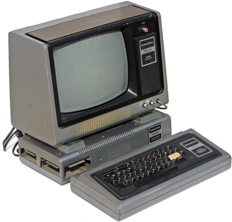
I love this project: That’s what we do at least some of the time, ain't it, muchachos? Take our pretty PCs out into the sticks in the service of our observing? I can’t lay claim to the title, though. It’s homage to a magazine column I read back at the very dawn of personal computing, the early 1980s. I’d just returned to Possum Swamp bearing my first PC, a RadioShack TRS-80 Model 1, aka “Trash 80.” It wasn’t a perfect computer, not e’en close, but I loved it very much and it was an exciting time to be into PCs whether you had a fancy Apple II or a proletarian machine from the 'Shack. At first blush, my TRS-80, whose graphics, if you could call them that, consisted of blocky ascii characters, didn't seem of much use for astronomy. That didn't matter; it sure played a mean game of Star Trek. When I could get the freaking tape to load off the cassette player that served at the Trash 80's storage medium, anyway. It was also obvious it would be usueful in amateur radio, at least for logging, and maybe even for sending and receiving radioteletype. But astronomy? Didn't seem like it...
https://uncle-rods.blogspot.com/2009/12/computin-in-country.html