DIY a Laser Rangefinder

If you're looking to learn Arduino&LVGL, you'll find a whole new world of possibilities for creating innovative projects. In this article, we'll explore the exciting realm of laser rangefinder using Arduino&LVGL. By following these steps, you'll not only gain a better understanding of Arduino&LVGL but also have a functional laser rangefinder of your own.
Supplies
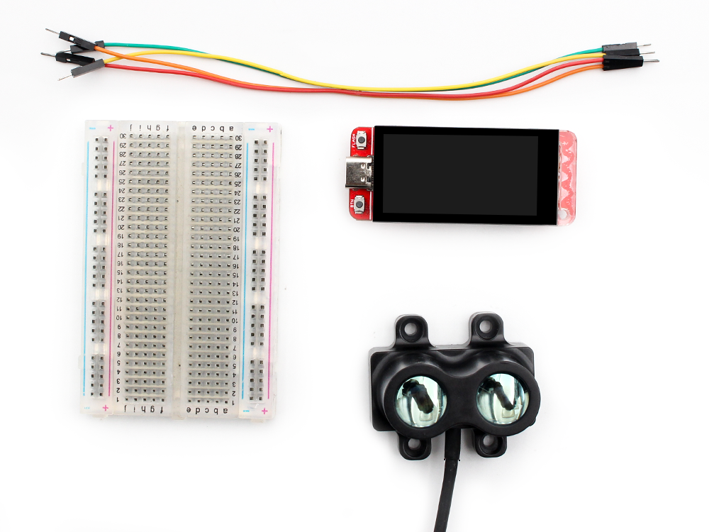

Single-point TOF Laser Ranging Sensor*1
Breadboard*1
Jumper Wires *1
Suitable size carton*1
Paper cutter*1
Hardware
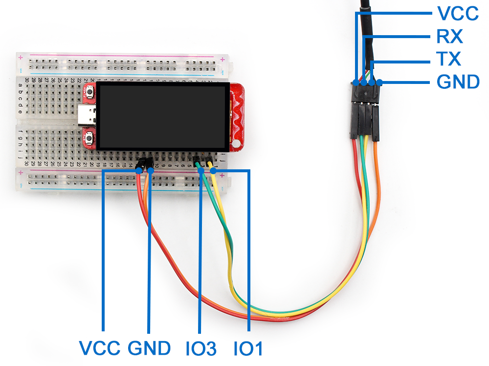
1: Connecting Matouch -1.9’ display to the breadboard;
2:Connect the Laser Ranging Sensor and the Matouch 1.9" display in the breadboard with jumper cables;
Please note:
Red wire:Power,connect to Matouch-1.9’display 5V
Green wire:RX to Matouch-1.9’display IO3
White wire:TX to Matouch-1.9’display IO1
Black wire:GND to Matouch-1.9’display GND
Using SquareLine: Creating Projects, Adding Widgets, Adding Events


- Create a New Project on LVGL;
- Add Buttons and Label on Screen;
- Add Button Event;
- Change the color to your liking;
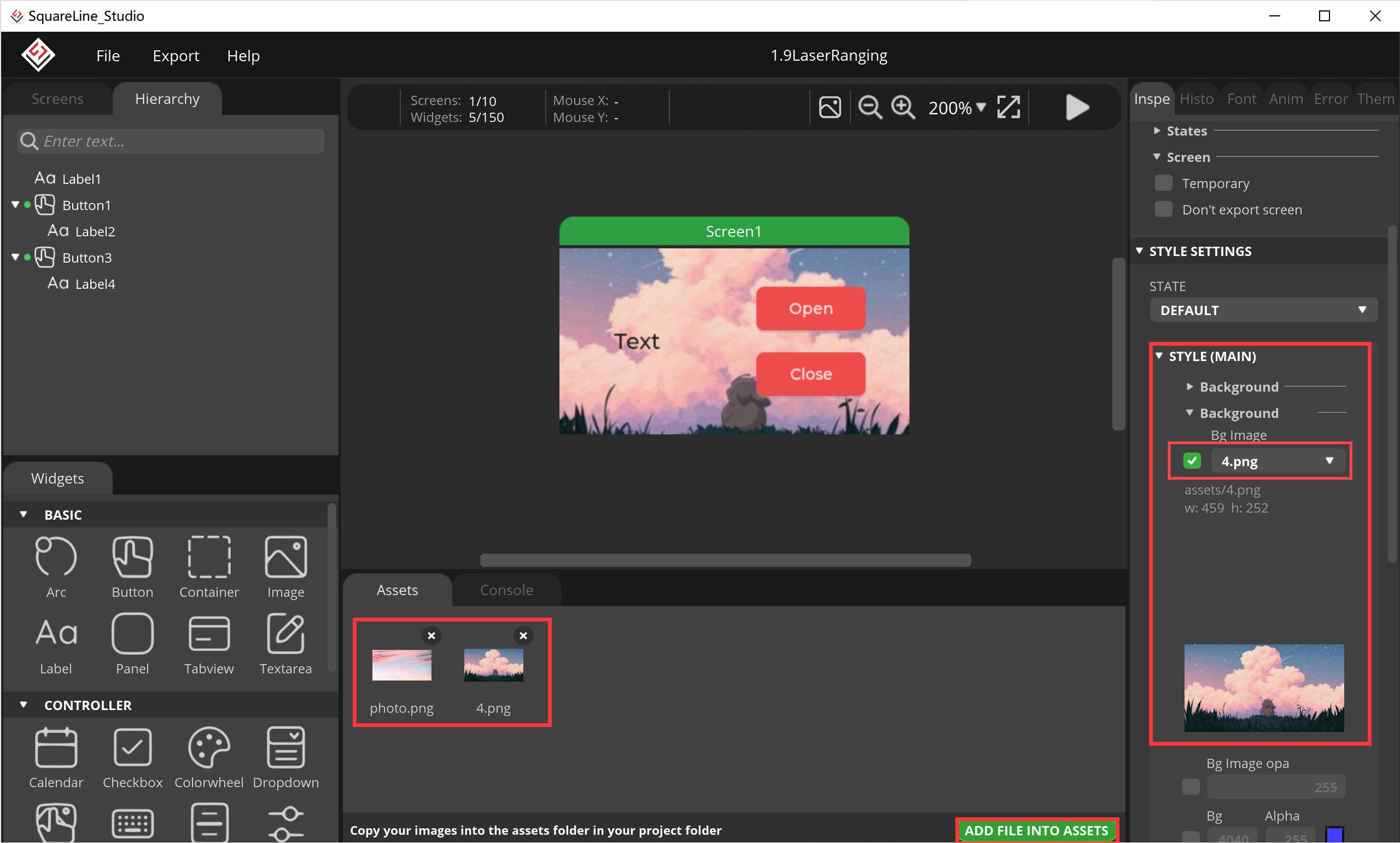
- According to your preferences in the "ADD FILE ASSETS" to add your favorite pictures, set your screen background;
- Set the location of the export code and Export UI files and Create Template Project;
Using Arduino: Adding Peripheral Code, Interface Interaction


- After exporting, copy lvgl_conf.h to the src folder in the lvgl folder;
- Open Ui_event.c in the LaserRanging\libraries\ui\src File of the Exported Project Document, Add the Key Event Code and Save
extern int work_flag;

void open_func(lv_event_t *e)

{

// Your code here

lv_obj_add_state(ui_Button1, LV_STATE_DISABLED);

lv_obj_clear_state(ui_Button3, LV_STATE_DISABLED);

work_flag = 1;

}


void close_func(lv_event_t *e)

{

// Your code here

lv_obj_add_state(ui_Button3, LV_STATE_DISABLED);

lv_obj_clear_state(ui_Button1, LV_STATE_DISABLED);

work_flag = 0;

}
3.Copy the Four Files to the Arduino Libraries, Usually in the Form of (C)/Users/Document/arduino/libraries;
4.Open Ui.ino Through the Arduino IDE to Add Your Code:
The code of leaser range can be refer to our github page;
Note: the Arduino esp32 board should be 2.0.17 and its previous version, we used 2.0.11 version;
5.Modify Your Code:
Use the Type-C USB cable to connect the board to the PC, select the development board "ESP32S3 Dev Module" and its port.
6.Click Upload Code;
Make an Enclosure and Put the Hardware Into


Cut the box to size. Secure the assembled hardware inside the box.
Result

As you can see in the picture above, this device works great.This handy little device can test the distance up to 20m and has an accuracy of 3cm. If you're interested, we've got a great tutorial that'll show you how to make your own laser rangefinder.
Detailed Operation Video

To gain a more comprehensive understanding of the assembly testing process, we invite you to view the accompanying video. We look forward to sharing further DIY projects with you in due course.