DIY Youtube Play Button Subscriber Counter - PCBWAY
by bluino_electronics in Circuits > Arduino
3369 Views, 18 Favorites, 0 Comments
DIY Youtube Play Button Subscriber Counter - PCBWAY
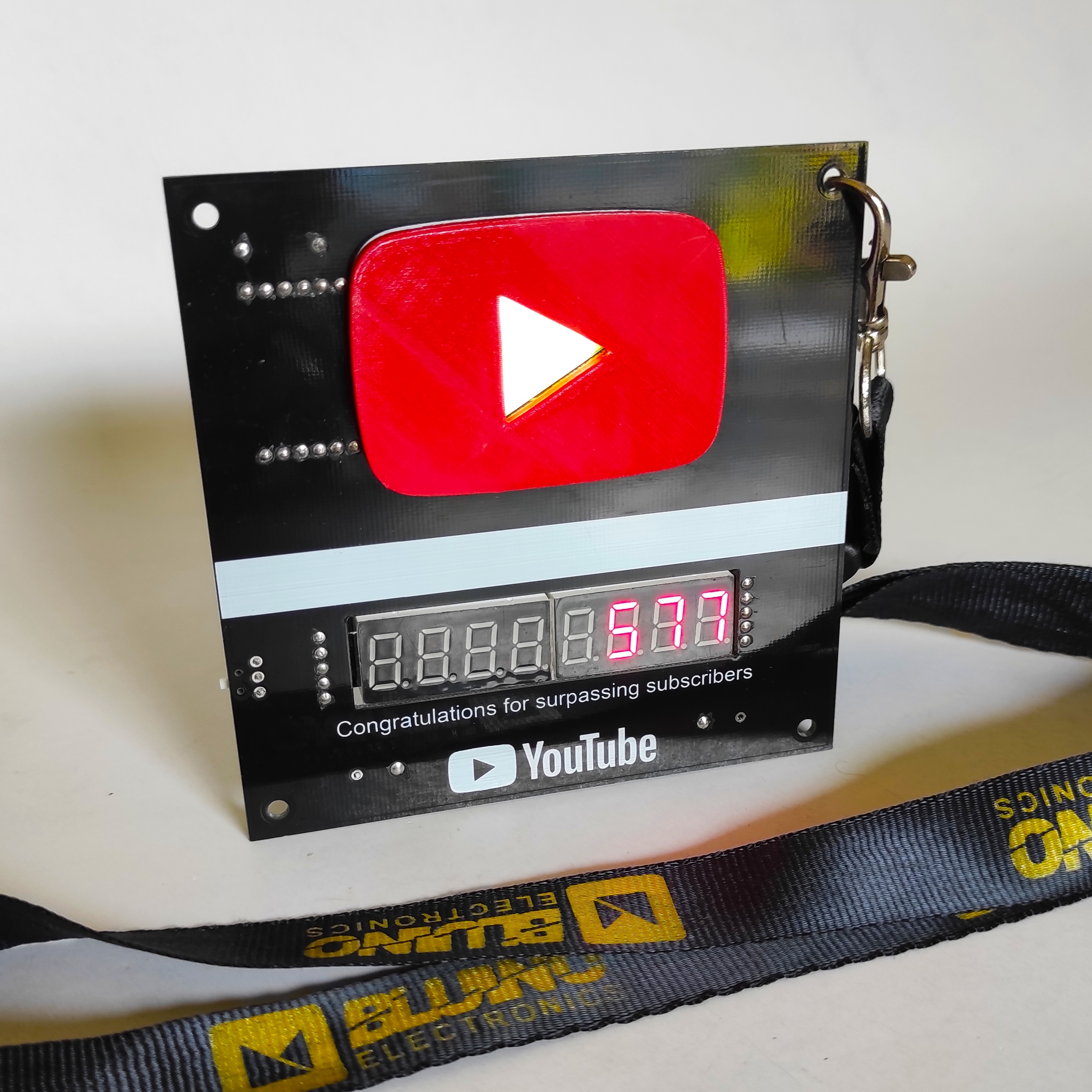
This project is so easy to build. Using the ESP8266 WiFi module can connect to the internet. Once connected, using the YouTube channel ID and the API key we obtain the YouTube subscribers count and then we print that value to a 7 segments screen module.
All we need is a PCB ordered from PCBWAY, WiFi module Wemos ESP8266 and a 7 segment display to print the values. The code refresh it self and it will beep each time the value changes.To make it look nice, I've red 3D printed the youtube icon.
Order PCB on PCBWAY
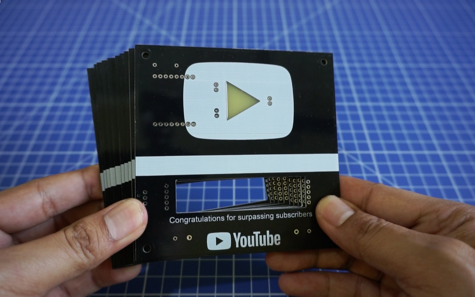
To make this project you need to order a prototype PCB on PCBWAY. How to order is very easy and you will get 10 Pcs PCB for $5 with very great PCB quality.
Step to Order:
1. SignUp/Log in on pcbway.com
2. Open this PCB project link YouTube Subscriber Counter ESP8266
3. Click Add to cart.
4. Wait moment for PCB review, then Click Check Out.
Part List
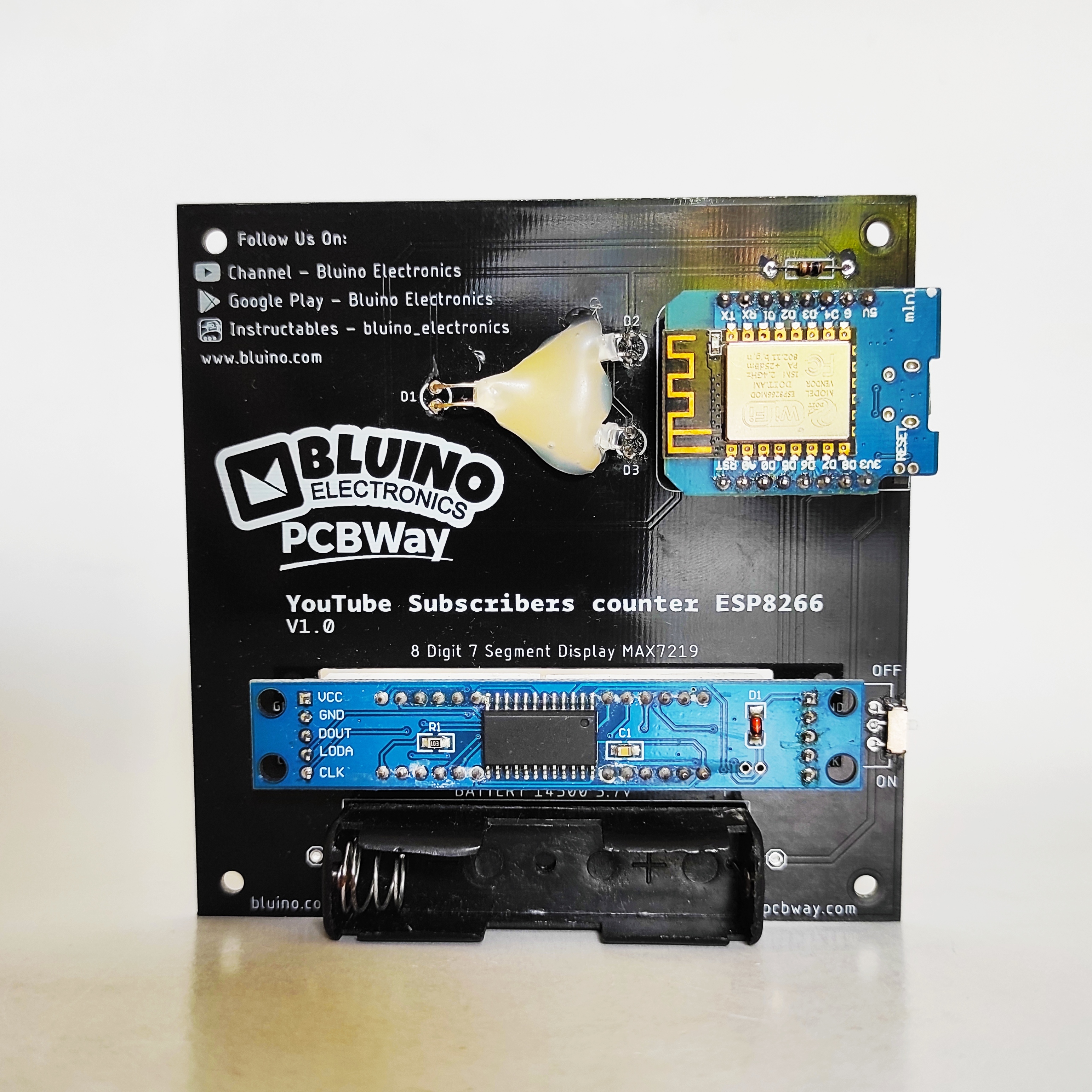
- PCB Youtube Subscriber Counter ESP8266
- Wemos D1 mini ESP8266
- 8 Digit 7segment MAX7219 module
- LED 3mm white diffused (3 pcs)
- R 100 ohm 1/4w
- Active Buzzer 5V
- Slide Switch SPDT SS-12D00G3
- Battery Holder AA
- 3D printed model Play Button
Schematics
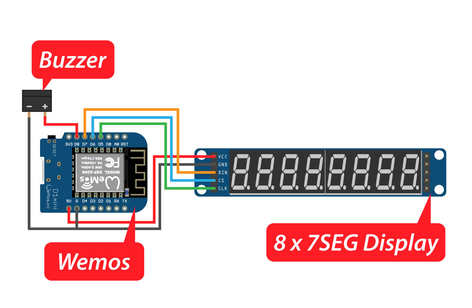
The schematic is very simple. In this instructables you not need to hook up wire, just solder the components to the PCB.
Soldering Components to PCB
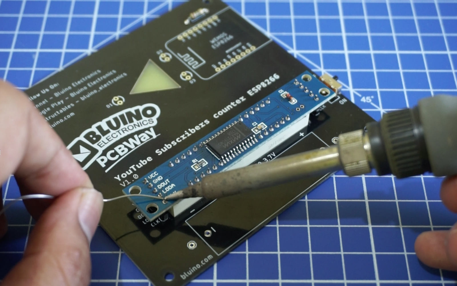
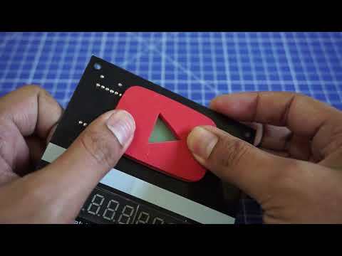
Solder all components on the PCB, for details you can follow step by step in the following video.
Covered LED Icon
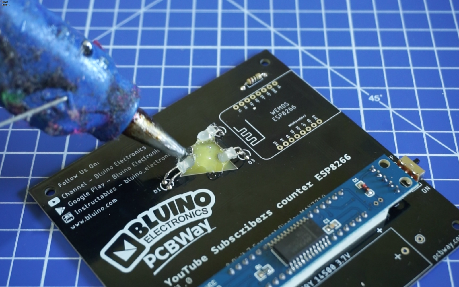
To make a glow on the triangle icon, on the back of the PCB you can cover it with clear glue gun. After that, coated again with a black glue gun to prevent shining on the back.
Attach the 3D Printed Play Button
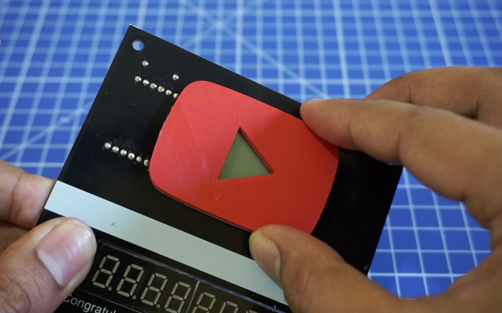
To make it look more charming, add a red 3D printed part play button on top of the pcb.
You can find the 3d file here:
But if you don't have a 3D printer you can replace it with other or even let i.
Get YouTube API Key and Channel ID
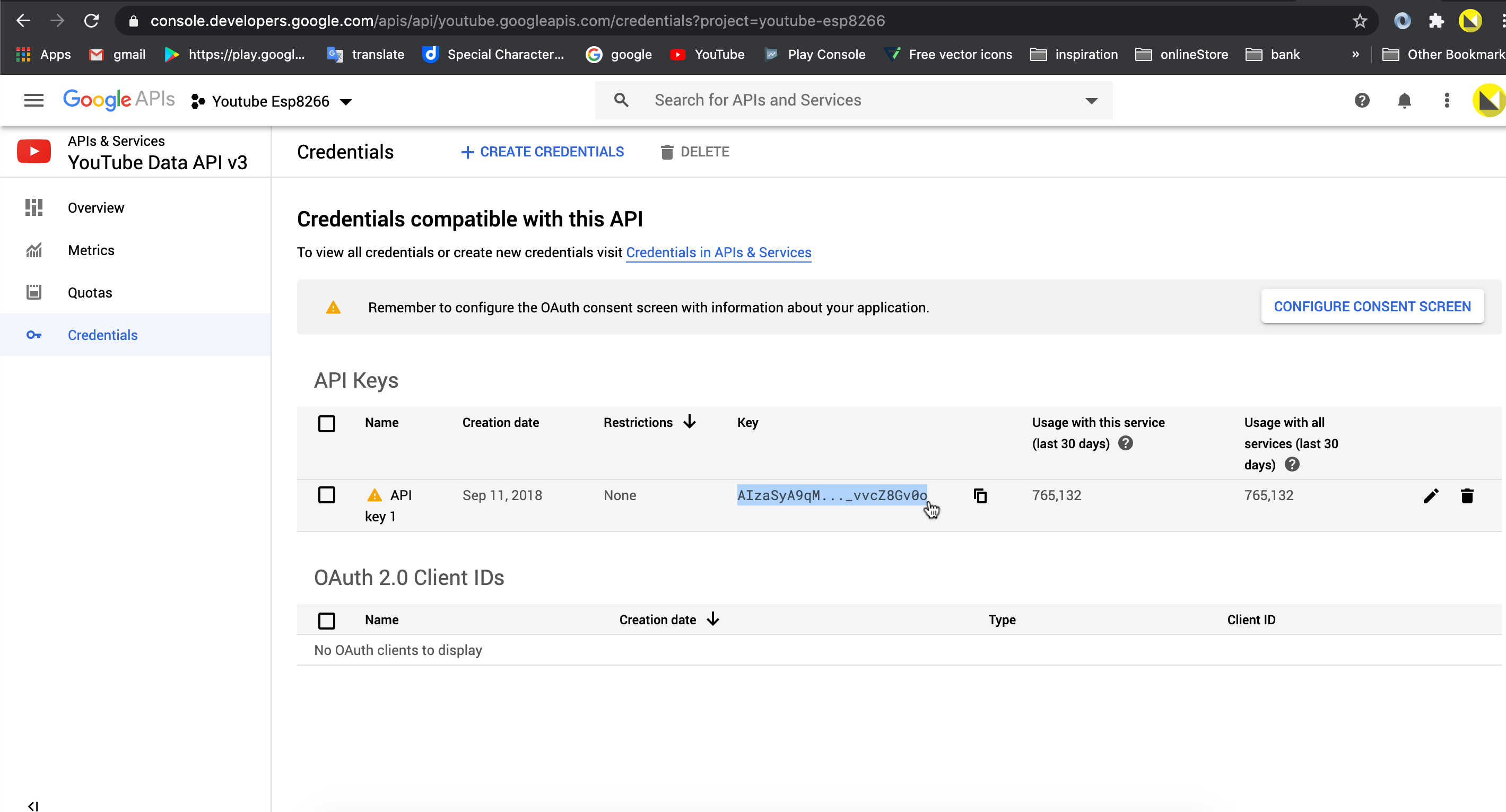
To get value of your subscribers In the Arduino code sketch you need to add the YouTube Channel ID and YouTube API Key, beside the network name and network password.
To get your YouTube Channel API Key, go to the Google API webpage:
https://console.developers.google.com and make sure you are logged in to your gmail account.
In the "Dashboard", click "Create Project". Choose a name for the project and click "Create". You should see "Enable APIS and Services". Click that and then write in the search box for "YouTube Data API v3". Enable it and "Create Credentials". In the page to create credentials you'll see in small letters the link to create a "API key". Then click "API restrictions" and select "YouTube Data API v3". Click create and then you'll see your key, which you need to add on the sketch.
You also need your Channel ID. You can find it in your advanced account settings. In the top right, click your profile picture and then Settings. From the left Menu, select Advanced settings. You'll see your Channel ID.
Test the API is working by going to this address in your browser:
https://www.googleapis.com/youtube/v3/channels?part=statistics&id=your_channel_id&key=your_api_key
Setup Arduino IDE for ESP8266
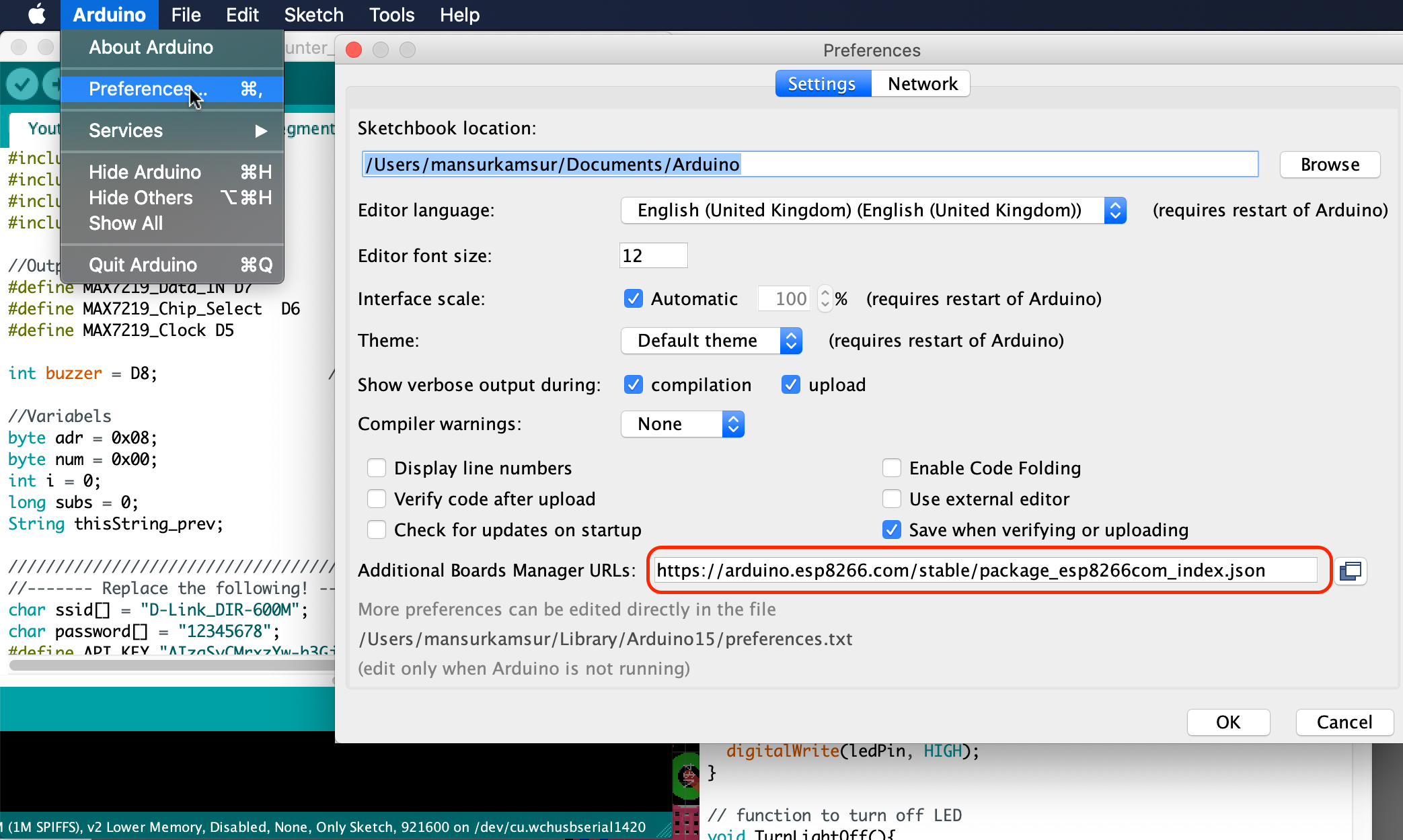
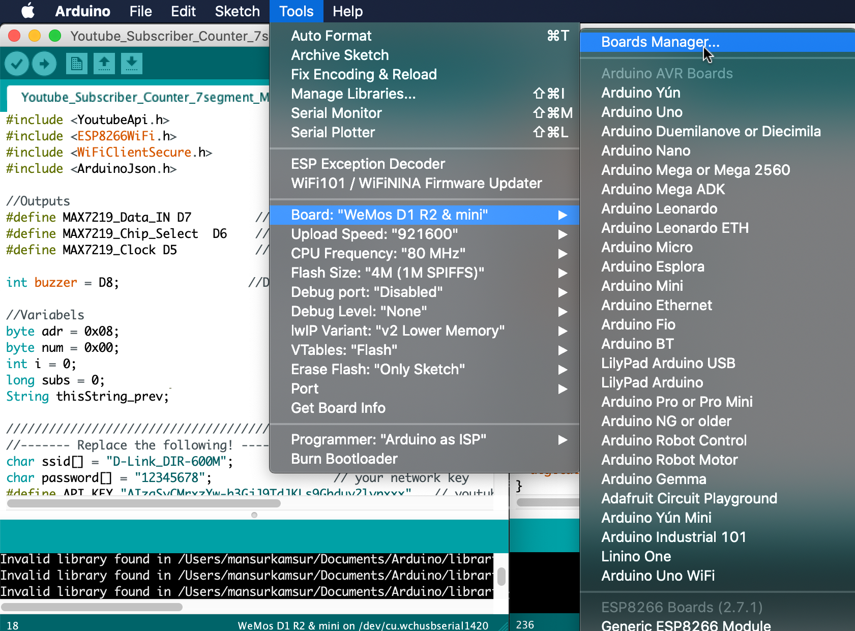
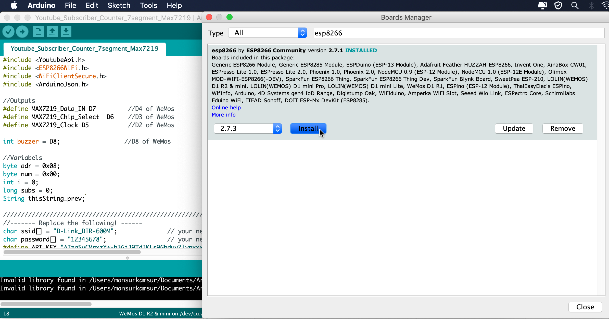
Before we look at the code we have to prepare the Arduino IDE with the libraries and also the core for the WeMos development board.
Firstly open the Arduino IDE
Go to files and click on the preference in the Arduino IDE
copy the below code in the Additional boards Manager
http://arduino.esp8266.com/stable/package_esp8266com_index.json
Click OK to close the preference Tab.
After completing the above steps , go to Tools and board, and then select board Manager.
Navigate to esp8266 by esp8266 community and install the software for Arduino.
Once all the above process been completed we are read to program our esp8266 with Arduino IDE.
Install Youtube API Library
Now let’s see how to get our YouTube data. The first download of Youtube API library here.
https://github.com/witnessmenow/arduino-youtube-api
Now open the Arduino IDE, and go to sketch, include library, add zip library and select the downloaded zip file. And we are done. Now we should have the examples for the YouTube subscriber count. This example is compatible with the ESP8266, it will connect to WIFI and get the subscriber count.
Code
#include <YoutubeApi.h>
#include <ESP8266WiFi.h>
#include <WiFiClientSecure.h>
#include <ArduinoJson.h>

//Outputs
#define MAX7219_Data_IN D7         //D4 of WeMos
#define MAX7219_Chip_Select  D6    //D3 of WeMos
#define MAX7219_Clock D5           //D2 of WeMos

int buzzer = D8;                  //D8 of WeMos

//Variabels
byte adr = 0x08;
byte num = 0x00;
int i = 0;
long subs = 0;
String thisString_prev;

//////////////////////////////////////////////////////////////////////////////////
//------- Fill the following! ------
char ssid[] = "";              // your network SSID (name)
char password[] = "";                 // your network key
#define API_KEY ""   // youtube API key from Google Developer Console
#define CHANNEL_ID ""               // makes up the url of channel

WiFiClientSecure client;
YoutubeApi api(API_KEY, client);
unsigned long api_mtbs = 10000; //mean time between api requests
unsigned long api_lasttime;   //last time api request has been done


void shift(byte send_to_address, byte send_this_data) {
  digitalWrite(MAX7219_Chip_Select, LOW);
  shiftOut(MAX7219_Data_IN, MAX7219_Clock, MSBFIRST, send_to_address);
  shiftOut(MAX7219_Data_IN, MAX7219_Clock, MSBFIRST, send_this_data);
  digitalWrite(MAX7219_Chip_Select, HIGH);
}


void setup() {
  Serial.begin(115200);
  delay(100);
  pinMode(buzzer, OUTPUT);
  digitalWrite(buzzer, LOW);
  delay(100);

  //Define the pins as outputs and disable CS
  pinMode(MAX7219_Data_IN, OUTPUT);
  pinMode(MAX7219_Chip_Select, OUTPUT);
  pinMode(MAX7219_Clock, OUTPUT);
  digitalWrite(MAX7219_Chip_Select, HIGH);
  delay(200);

  //Setup of the 7seg module
  shift(0x0f, 0x00); //display test register - test mode off
  shift(0x0c, 0x01); //shutdown register - normal operation
  shift(0x0b, 0x07); //scan limit register - display digits 0 - 7
  shift(0x0a, 0x0f); //intensity register - max brightness
  shift(0x09, 0xff); //decode mode register - CodeB decode all digits

  // Set WiFi to station mode and disconnect from an AP if it was Previously
  // connected
  WiFi.mode(WIFI_STA);
  WiFi.disconnect();
  delay(100);
  // Attempt to connect to Wifi network:
  Serial.print("Connecting Wifi: ");
  Serial.println(ssid);
  WiFi.begin(ssid, password);
  while (WiFi.status() != WL_CONNECTED) {
    Serial.print(".");
    delay(500);
  }
  Serial.println("");
  Serial.println("WiFi connected");
  Serial.println("IP address: ");
  IPAddress ip = WiFi.localIP();
  Serial.println(ip);
}

void loop() {

  if (millis() - api_lasttime > api_mtbs)  {
    if(api.getChannelStatistics(CHANNEL_ID))
    {
      unsigned long Count = api.channelStats.subscriberCount;
      Serial.println(Count);
      String thisString = String(Count, DEC);

      if(thisString != thisString_prev)
      {
        digitalWrite(buzzer,200);
        delay(1000);
        digitalWrite(buzzer,LOW);
      }

      thisString_prev = thisString;

      i =  thisString.length();//This variable will go character by cahracter and send the value to the 7 segment display
      if(i==8)
        {
          shift(0x0b, 0x07); //scan limit register - display digits 0 thru 7
          adr=0x01;
        }
        if(i==7)
        {
          shift(0x0b, 0x06); //scan limit register - display digits 0 thru 7
          adr=0x01;
        }
        if(i==6)
        {
          shift(0x0b, 0x05); //scan limit register - display digits 0 thru 7
          adr=0x01;
        }
        if(i==5)
        {
          shift(0x0b, 0x04); //scan limit register - display digits 0 thru 7
          adr=0x01;
        }
        if(i==4)
        {
          shift(0x0b, 0x03); //scan limit register - display digits 0 thru 7
          adr=0x01;
        }
        if(i==3)
        {
          shift(0x0b, 0x02); //scan limit register - display digits 0 thru 7
          adr=0x01;
        }
        if(i==2)
        {
          shift(0x0b, 0x01); //scan limit register - display digits 0 thru 7
          adr=0x01;
        }
        if(i==1)
        {
          shift(0x0b, 0x00); //scan limit register - display digits 0 thru 7
          adr=0x01;
        }
        i=i-1;


      while (i >= 0)
      {
        if(thisString[i] == '0')
        {
        num = 0x00;
        }
        if(thisString[i] == '1')
        {
        num = 0x01;
        }
        if(thisString[i] == '2')
        {
        num = 0x02;
        }
        if(thisString[i] == '3')
        {
        num = 0x03;
        }
        if(thisString[i] == '4')
        {
        num = 0x04;
        }
        if(thisString[i] == '5')
        {
        num = 0x05;
        }
        if(thisString[i] == '6')
        {
        num = 0x06;
        }
        if(thisString[i] == '7')
        {
        num = 0x07;
        }
        if(thisString[i] == '8')
        {
        num = 0x08;
        }
        if(thisString[i] == '9')
        {
        num = 0x09;
        }


        shift(adr, num);


        adr=adr+0x01;
        i=i-1;
      }
    }
    api_lasttime = millis();
  }
}
Powered Up
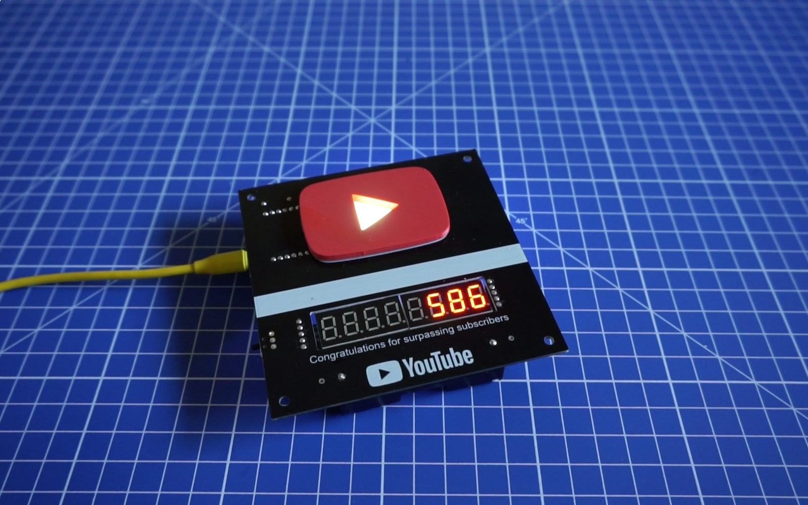
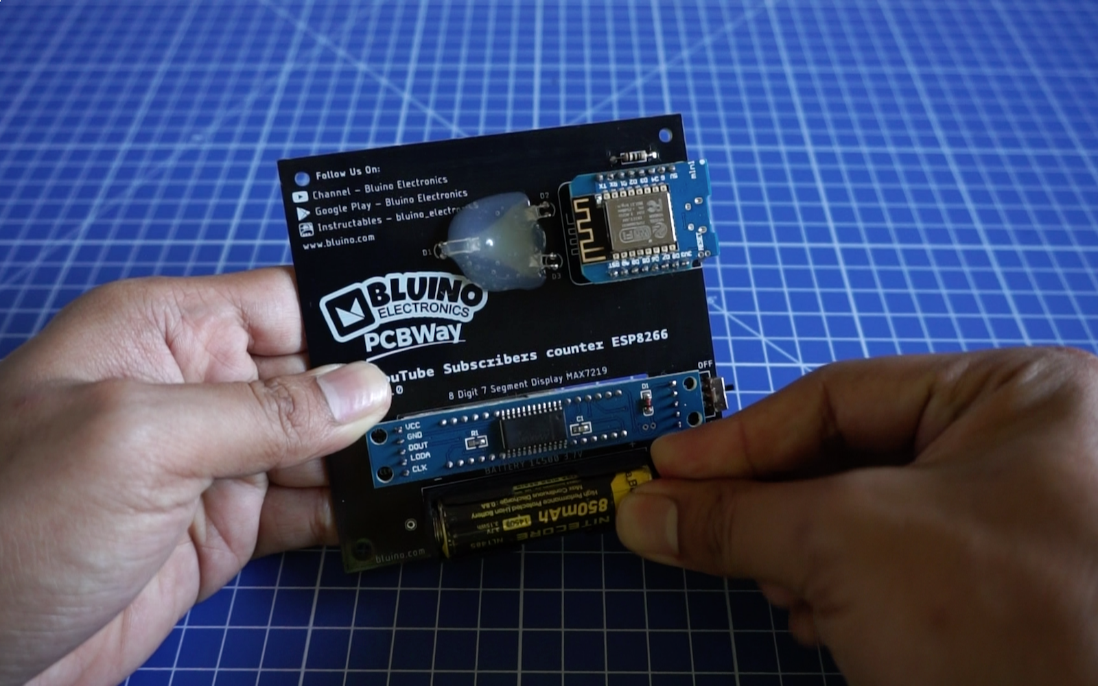
To supply the circuit you can use directly the USB connector with a voltage of 5 volts or you can use single Li-ion battery 14500 (size AA) 3.7V.