DIY Xbox 360 Controller Receiver Using LinkIt ONE
by abdullahsadiq7 in Circuits > Arduino
7473 Views, 70 Favorites, 0 Comments
DIY Xbox 360 Controller Receiver Using LinkIt ONE
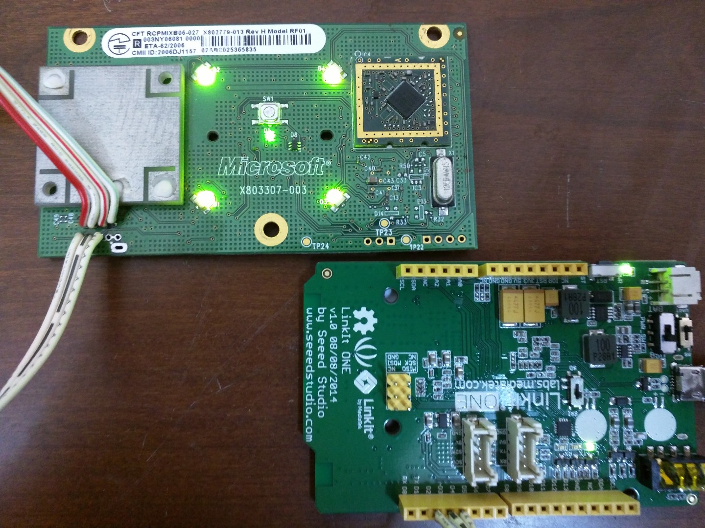
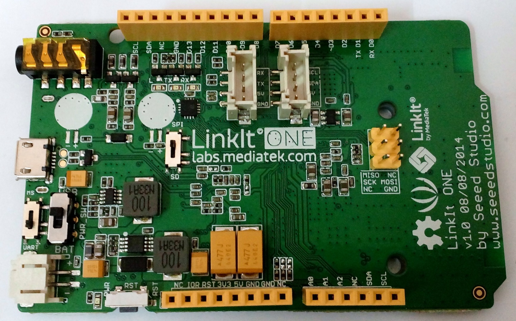
In this Instructable, I will tell you how to make an Xbox 360 controller receiver, to connect your Xbox 360 controller to your PC to play games.
To do this, you will need the following items:
- Xbox 360 fat ROL board
- LinkIt ONE and its cable to connect it to your PC
- Two 1N4001 diodes
- A spare USB cable
I was tired of playing computer games using a keyboard, and so made a receiver using a ROL board, by following Timinator01’s instructable “Diy Xbox wireless controller adapter for Pc”. I made it as described, but sadly, could not get the syncing part to work with the UNO. So I could play a game but not sync my controller using a PC. For that, I had to plug the module in another Xbox 360 motherboard and sync it, which was very inefficient. But then I just tried using the LinkIt ONE and surprisingly, it worked like a charm, with a little modification to the code.
Setting Up the ROL Board and Drivers
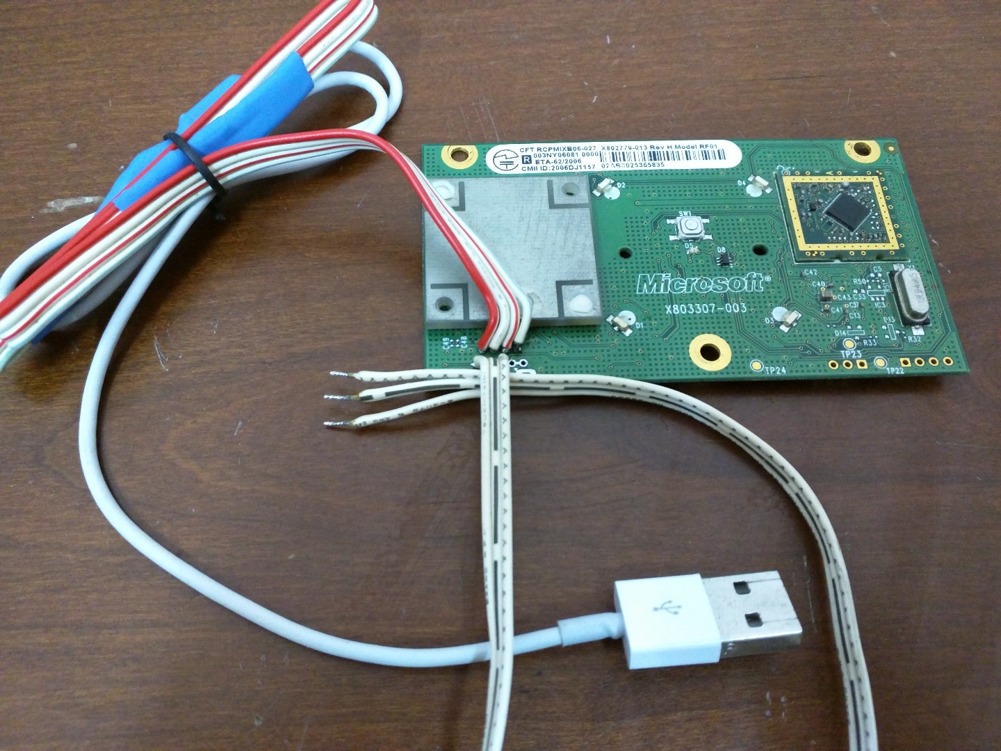
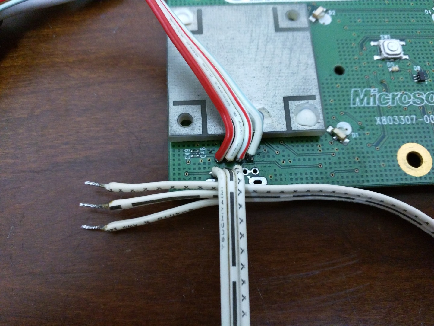
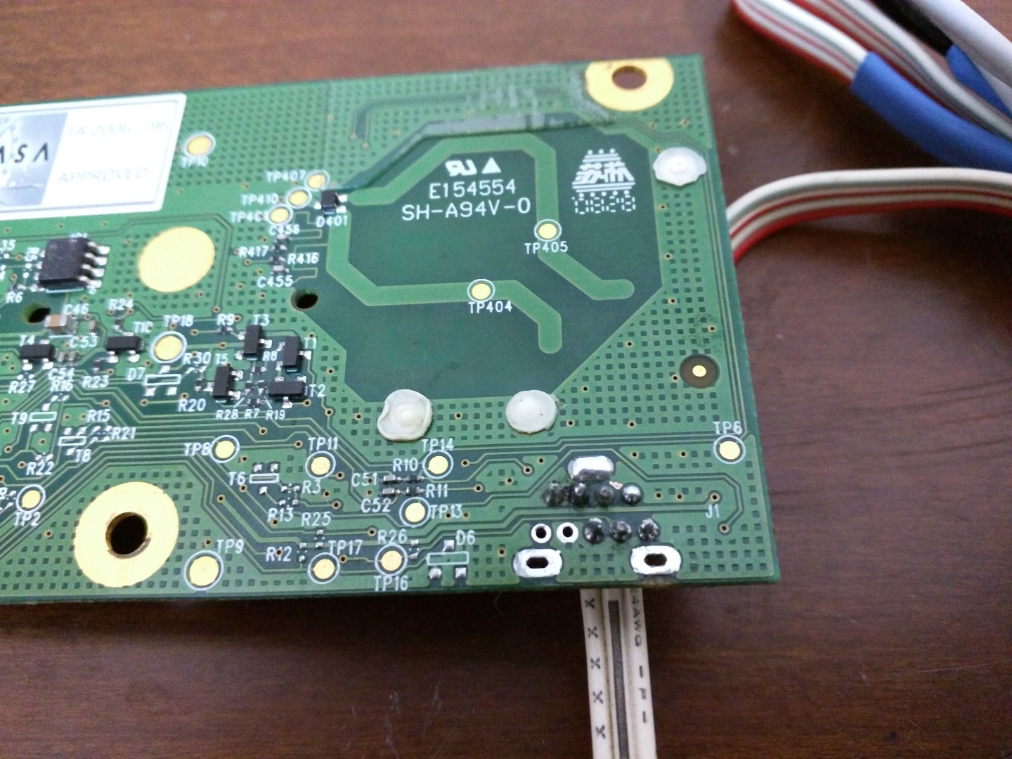
To set-up the module and the drivers, you should read through Timinator01’s instructable here. He has given detailed instruction on how to do that, so it is better if you read through his Instructable. I will just show you pictures of my completed ROL board.
Before proceeding, I expect you to have gotten your ROL board to work with your controller which is already synced to it. In the next step, I will tell you how to use the LinkIt ONE to sync another controller with that module, so that you will not need to plug in the ROL into an Xbox 360 motherboard and then be able sync it.
I would have taken pictures of the diodes, but because I had made this quite a while ago for my own use from Timinator01’s instructable, I did not take any pictures now as I did not want to open it; I had fixed it using heat shrink tubing.
LinkIt ONE Part and the Code
The code given on Timinator01’s Instructable should work for an UNO (I really have no idea why it did not work for me). But because we are using a LinkIt ONE, we will need to modify it. The only problem is the sleep function using the AVR library. Because the LInkIt ONE does not have the AVR library, we can just remove the sleep function in the code and it will work perfectly. Below is the modified code. Copy that into a blank sketch and upload that to your LinkIt ONE.
<p>/* Arduino code to communicate with xbox 360 RF module.<br>Original work by (yaywoop) / additional ideas from Alexander Martinez - modified by dilandou (www.dilandou.com, www.diru.org/wordpress) */</p><p>#define sync_pin 2 //power button repurposed for sync button (pin 5 on the module)
#define data_pin 3 //data line (pin 6 on the module)
#define clock_pin 4 //clock line (pin 7 on module) </p><p>int led_cmd[10] =  {0, 0, 1, 0, 0, 0, 0, 1, 0, 0}; //Activates/initialises the LEDs, leaving the center LED lit.
int anim_cmd[10] = {0, 0, 1, 0, 0, 0, 0, 1, 0, 1}; //Makes the startup animation on the ring of light.
int sync_cmd[10] = {0, 0, 0, 0, 0, 0, 0, 1, 0, 0}; //Initiates the sync process.
volatile boolean sync_enable = 0;</p><p>void sendData(int cmd_do[]) {
  pinMode(data_pin, OUTPUT);
  digitalWrite(data_pin, LOW);    //start sending data.
  int prev = 1;
  for (int i = 0; i < 10; i++) {</p><p>    while (prev == digitalRead(clock_pin)) {} //detects change in clock
    prev = digitalRead(clock_pin);
    // should be after downward edge of clock, so send bit of data now
    digitalWrite(data_pin, cmd_do[i]);</p><p>    while (prev == digitalRead(clock_pin)) {} //detects upward edge of clock
    prev = digitalRead(clock_pin);
  }
  digitalWrite(data_pin, HIGH);
  pinMode(data_pin, INPUT);
}</p><p>void initLEDs() {
  sendData(led_cmd);
  delay(50);
  sendData(anim_cmd);
  delay(50);
}</p><p>void setup() {
  Serial.begin(9600);
  pinMode(sync_pin, INPUT);
  digitalWrite(sync_pin, HIGH);
  pinMode(data_pin, INPUT);
  pinMode(clock_pin, INPUT);
  delay(2000);</p><p>  initLEDs();
}</p><p>void loop() {
  Serial.println("Syncing.");
  sendData(sync_cmd);
  delay(10000);
}</p>
Wire it up as below:
- Pin 5 on the ROL (Sync pin): Pin 2 on the LinkIt ONE
- Pin 6 on the ROL (Data pin): Pin 3 on the LinkIt ONE
- Pin 7 on the ROL (Clock pin): Pin 4 on the LinkIt ONE
Once done, move on to the next step.
Testing and Usage

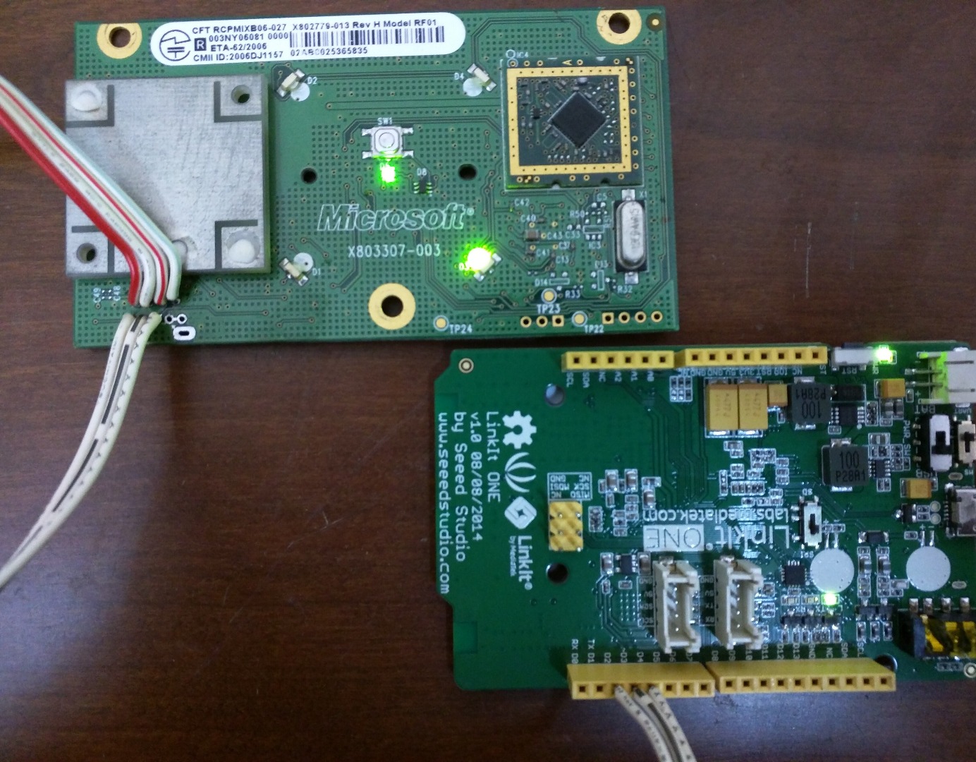
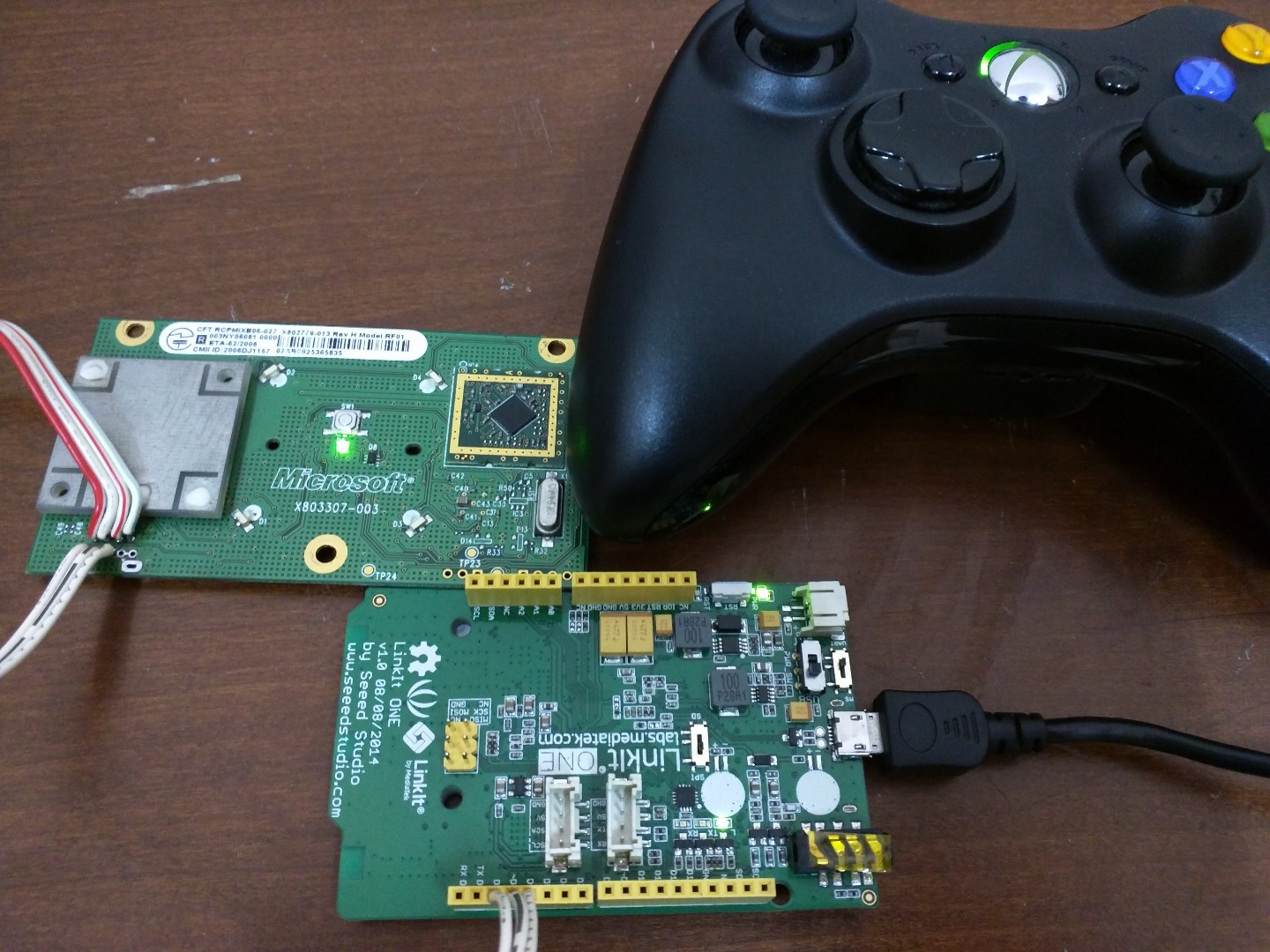
Plug in the USB to power the ROL board, and then plug in the LinkIt ONE’s power cable to your PC too. Once done, you should see the LEDs on the ROL light up, showing the switching on animation. When you see that, just press the sync button on your controller and it will automatically be synced to your controller. Then remove the LinkIt ONE and open your control panel and ‘Game Controllers’ from there you can check that your controller is connected properly and working. The coding on the LinkIt ONE makes it sync every 10 seconds; you can modify that as you wish, but I do not think there is any use for that.
Thanks to Timinator01, for posting a detailed and informative Instructable, and also to Alex Martinez and Dilandou for the original code and project.
If you have any problem, just leave a comment below and I will help you out.