DIY Vernier Scale
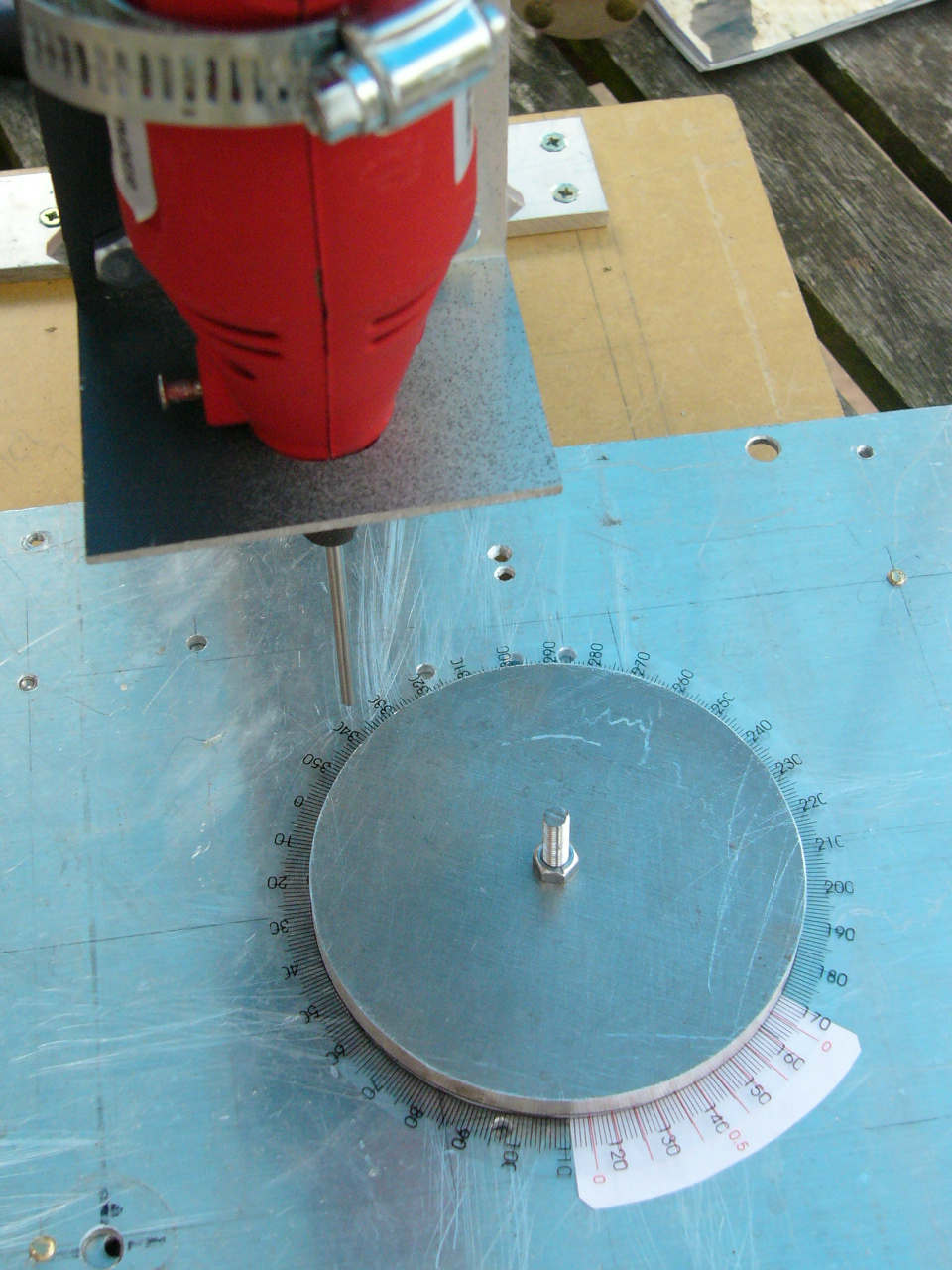

I needed a small but precise rotary table to cut discs and do light radial milling on my mini drill stand. I decided that an accuracy of 0.1 degree was enough, but it obviously called for some form of Vernier measure. This seemed daunting at first, but after playing around a bit with Coreldraw it turned out to be surprisingly simple!
If you have read this far, you probably don't need a tutorial on verniers, but for the curious here is a short review:
Verniers allow the user to make precise fractional measurements of distance.
To do this you need a ruler with two scales. One scale is moveable and marked in the ordinary manner in millimetres, inches or degrees or whatever you fancy. The other ruler is fixed and graduated in a special way, depending on the resolution required.
We'll decide on a linear scale with 0.1mm resolution.
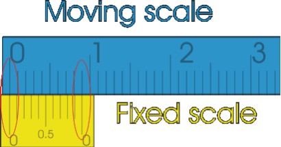
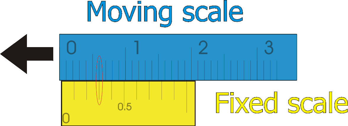
Therefore, as in the first picture, our moveable scale (blue) is graduated in the usual millimetres. (I only work in metric).
If you look closer at the yellow (fixed) scale you'll notice that it also has 10 divisions but spans only 9mm. It follows then that each of the fixed divisions is only 0.9mm in length which in turn means that the difference in length between the fixed and moveable divisions is exactly 0.1mm, which is our required resolution.
Therefore: to get the first divisions in line the moving scale has to travel to the left 0.1mm,
to get the second divisions in line the moving scale has to travel to the left 0.2mm,
to get the third divisions in line the moving scale has to travel to the left 0.3mm,
and so on.
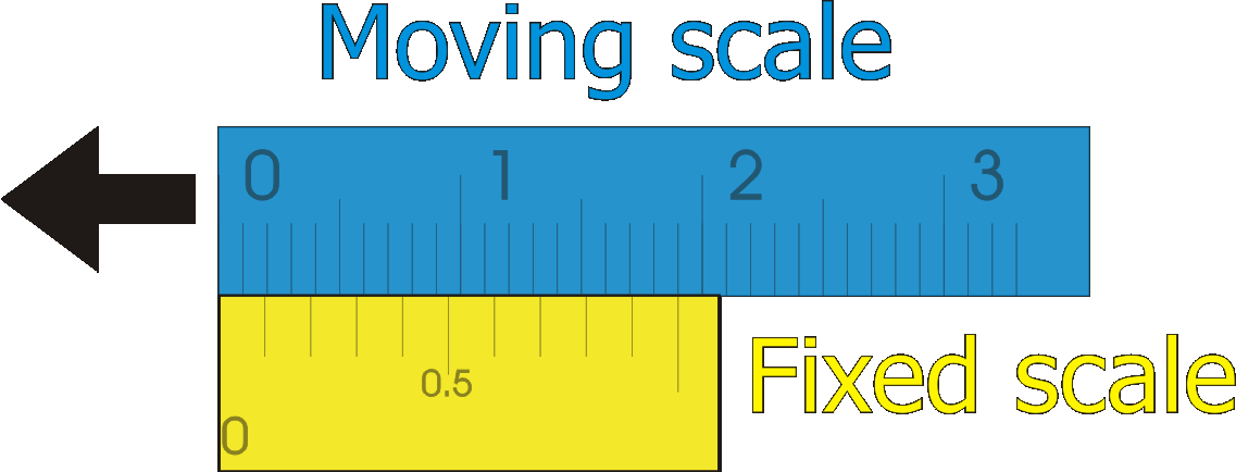
Doing all this in only 10mm of space makes things a bit crowded so we'll expand the fixed scale in 1 + .9 = 1.9 mm increments as in the following picture.
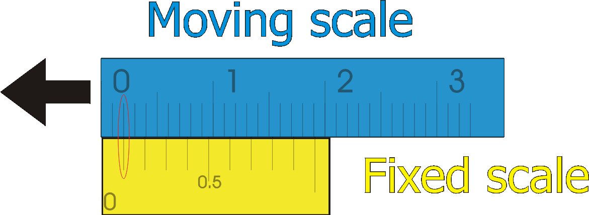
That makes reading the Vernier a lot easier, as in the following images showing 0.1mm, 0.3mm and 20.5mm excursions.
Now that you know how a Vernier works, you can make your own.
All you need is a printer.
This time we'll do a circular scale in degrees with an 0.1 degree resolution, in other words a protractor.
Setting the Stage
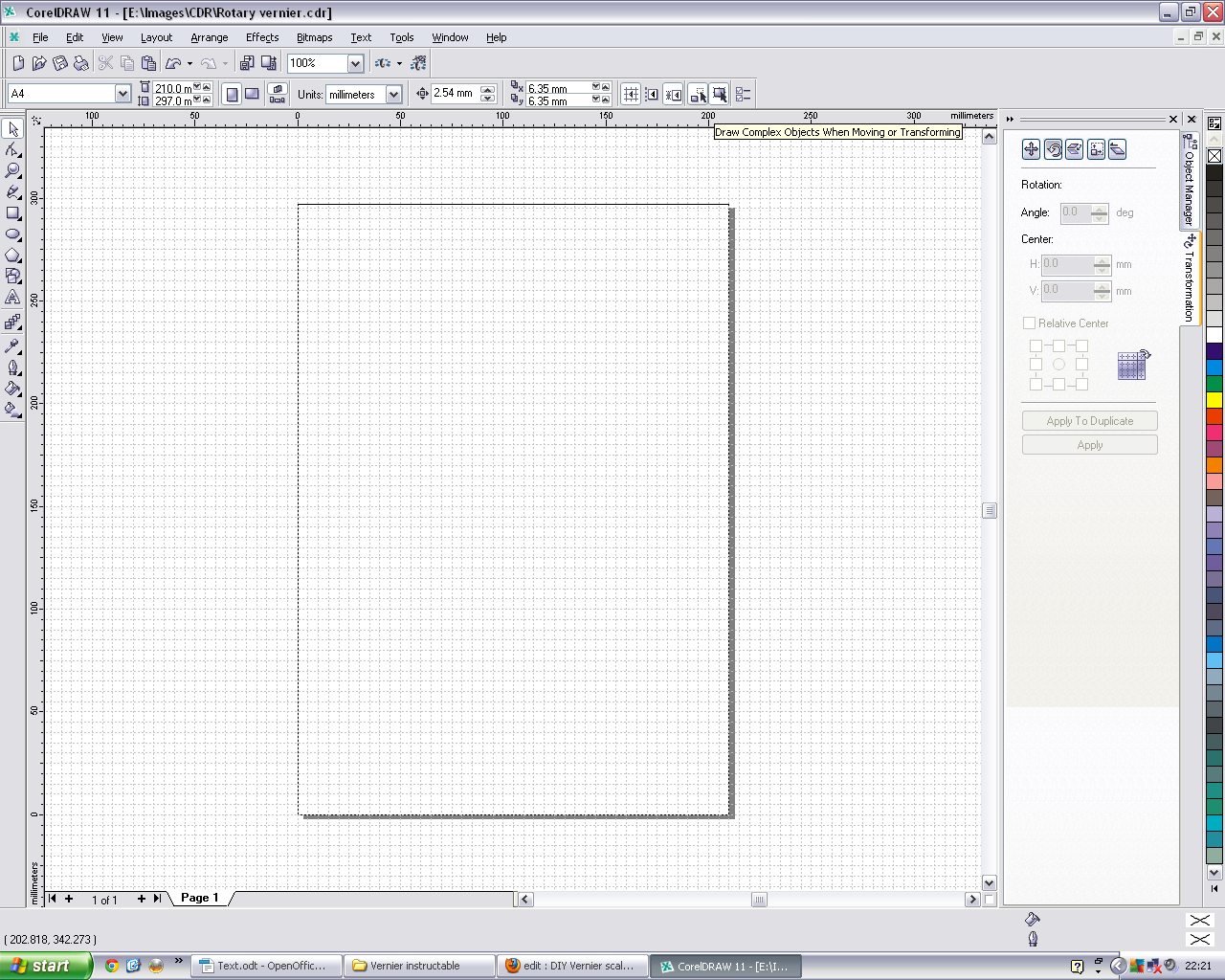
Create layers
Fire up you favourite drawing/CAD program, eg. Coreldraw, Inkscape etc.
I use an ancient version of Coreldraw which works well for me so I'll base the Instructable on this.
So: Ensure that you have the Object Manager and Transformations dockers enabled. Both are found under Window/Dockers on the toolbar. Be sure to put the various parts of your protractor on different layers to make printing easier. For my purpose I created different layers for:
Orientation
Graduations
Numerals
Static scale
Also make sure that “snap to grid ” is enabled (control + y). The grid was set to 1mm.
Zoom in to the origin of the page, ie x = 0, y = 0
Orientation
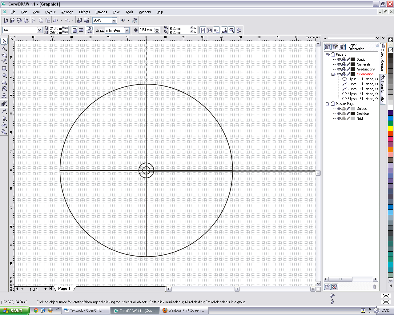
This is where the basic outlay of the protractor lies. I needed to mark the centre with a 3mm circle for a pilot hole and a 8mm circle for a shaft diameter. Another 94mm diameter circle marks the edge of the protractor Therefore, zoom in on the origin and draw the circles, keeping control + shift depressed to centre the circles on the cursor. I also drew a big cross to mark 90 degree increments.
Adding Detail
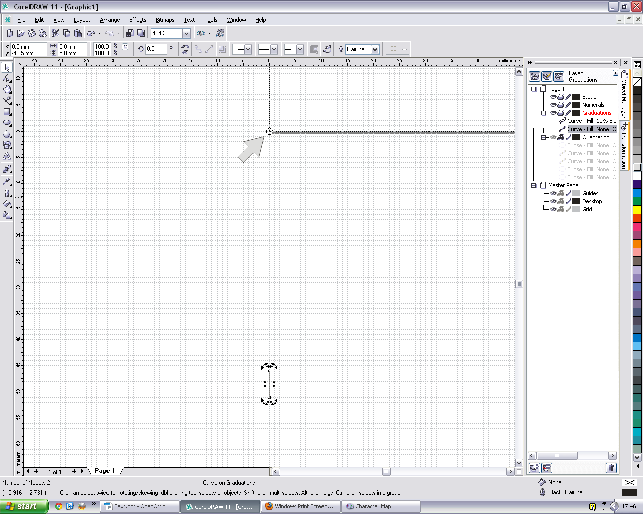
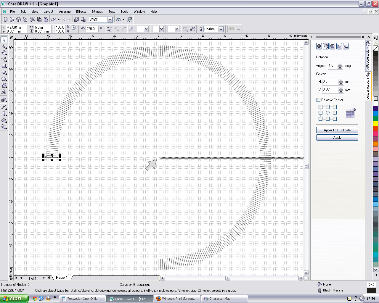
Enable the “Graduations” layer. Choose whatever length you want the lines to be and draw just one at the 270º mark. Reselect it to enable the rotation facility to appear. Now move the centre of rotation to the origin of the page. (x = 0 and y = 0, see the arrow on the screenshot)
Click the line again to enable the ordinary selection frame again, then go to the Transformations docker. Select “rotation” and set the rotation to 1º and perform this action. Hereafter just keep “control + d” depressed to complete a full circle of graduations. I disabled the “Orientation” layer for clarity.
More Detail
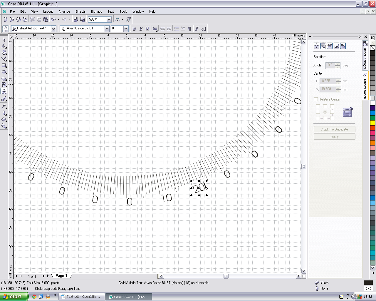
Here is where you add the numbers. Select the vertical graduation at 270º and extend its length a bit. Remember to replace its centre of rotation to the origin then rotate a copy to 5º .
Select the text tool and put any digit exactly where you want it in relation to the 270º mark. You may need to disable “Snap” temporarily for accuracy. Now select and group (control + g) the digit, the 270º line and the 5º line. Replace the centre of rotation to zero again and rotate duplicates by 10º increments for the full circumference of the circle. When this is done you'll need to select each of the digits and change it to the correct value. You use “control + L click” to select within a group. Then switch to the Text tool. Thirty six times.Tedious. Sorry.
Once you've done all this it's a good idea to go to each of the layers and group the contents. Also remember to save frequently!
The Meat
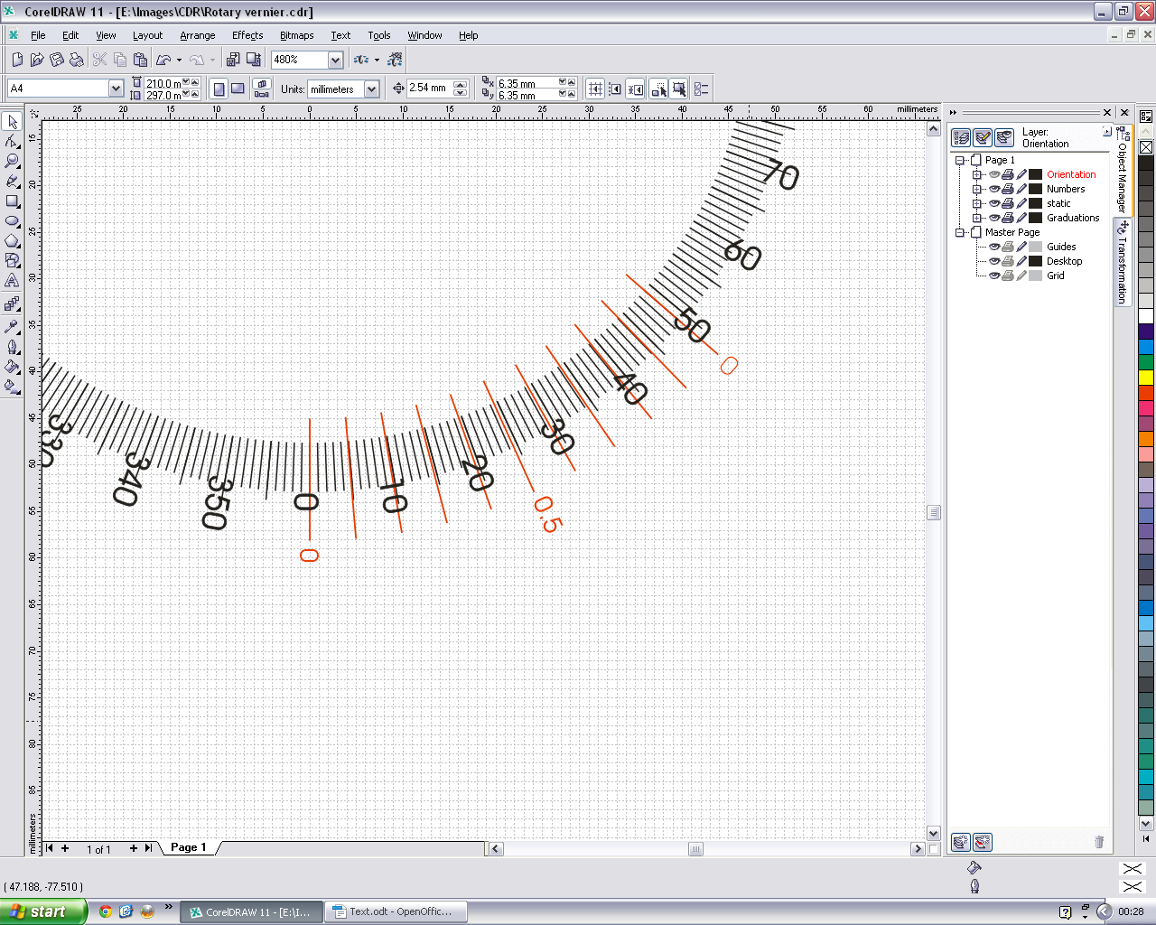
Static scale: The Vernier
Since we need to resolve 0.1º we'll need to space the graduations by 0.9º increments, but to space it more conveniently we'll increase it to 3.9º .
Therefore on a new layer draw a vertical graduation line at the 0º position, move the centre of rotation to the midpoint of the protractor and duplicate the line at 3.9º increments as you had done before.
Add the numerals as shown.
Testing
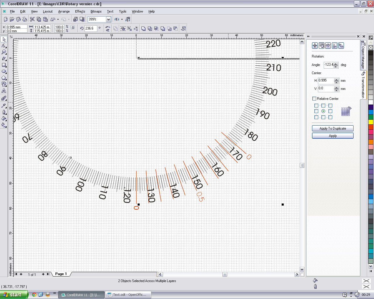
Now we have to test, so make only the Graduation and Numerals layers visible in the Object manager, select “All” (control + a) and move the centre of rotation to the centre of the protractor.
Make the static scale visible now, and check that the zeros of both the static scale and the protractor are superimposed.
Select the protractor graduations and the numerals together and check that the centre of rotation is indeed at the centre of the protractor.
In the transformations panel select “Rotation” and set it to any figure. I chose -123.4 degrees because the protractor is numbered anticlockwise for my application. Click on “Apply” and the Vernier should should indicate this angle. If you get unexpected results check all rotation points.
Printing
Any inkjet or laser printer should do. Laser printing gives more durable results and is probably the best.
In my case I printed all the layers except the Vernier scale on transparent sheet and glued it to the underside of the rotating table (see photo). The Vernier scale was glued to the base with the zero line aligned along the long axis of the drill platform. Viewed from above the scales are superimposed for almost parallax free measurement.
The above is a working example suited to my needs but can be adapted fairly easily to your specifications.
Best of luck!