DIY Stencil for PCBs
When you have been making circuit boards for projects, you will eventually find that through hole components are just too big to fit in a specific location that you want to put your project, whether it be in a case or stuffed behind an existing project. I have switched over to designing mostly surface mount circuit boards for one main reason, holes are a pain to drill by hand. When you are making your own custom circuit boards at home using an etching solution or something similar, then you have to drill all of your through hole component holes by hand unless you are fortunate enough to have access to a router or other CNC type machine. When making board designs that use small pitch, you will eventually want to use a solder paste stencil to allow you to get a nice even coating on solder paste on your pads without having to worry about solder bridges when you cook your board in a reflow oven, or toaster, or on a hot plate.
In this Instructable I will try to show you how you can make a stencil that can be printed and then etched, much in the same that that you can make PCBs at home.
I Am a Thief!
This process for developing solder paste stencils is not something that I randomly came up with one day. I had a need so I did what I always do, I started to Google! I came across some YouTube videos and a blog where a guy had this little scheme to make stencils. This is simply my interpretation of it and what I believe works best. This is also a way for me to share my experience and post information into more places for more people to find and use and abuse!
Let's get making!
Tools/Equipment
There are a few basic "tools" and pieces of equipment and materials that you will need to acquire in order to create one of these stencils.
- Eagle CAD software
- ViewMate gerber viewer, the free version works fine
- laser printer
- photo paper or glossy paper
- Acetone
- Muriatic Acid
- Hydrogen Peroxide
- Drink can(soda/beer)
- regular desk tape, not masking tape
- clothes iron
Preparing Your Eagle File
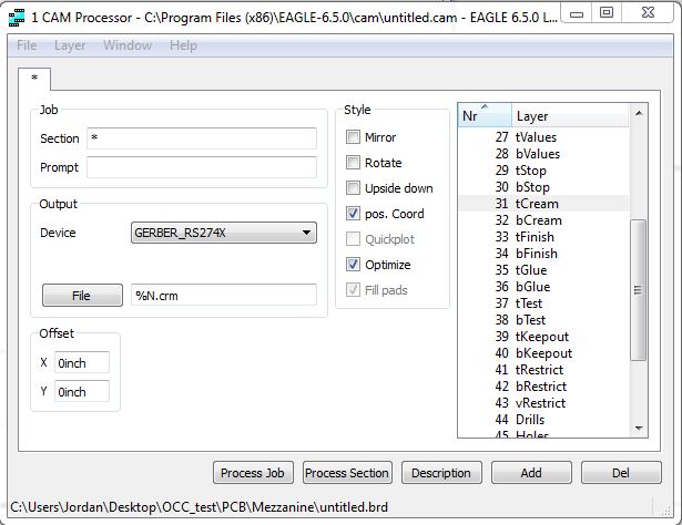
Once you have your completed board layout done in Eagle, you will need to export a Gerber file that contains only the data for the SMD component pads. To do this you will go to the Eagle control panel window and go to File->New->Cam Job. In the new window go to File->Open->Board and navigate to your board location in the explorer and open it. Once your board is open in the cam job we need to make sure that it will give us the proper Gerber format.
To do this, click the drop down for 'Device' and select the option for 'GERBER_RS274X'. In the box next to the File button below 'Device', you can type in the name that you want your Gerber file to have. I chose to use '%N.crm'. The %N takes names it the same as my board file and will save it in the same folder. The .crm is just an arbitrary extension that I chose, crm for cream since we will be using the cream layer, but you can make the extension really whatever you want.
In the list on the right side, you need to make sure that the tCream layer is highlighted and no other layers. This will export the top cream layer of your eagle file, which is just the SMD component pads with no traces. Click the 'Process Job' button, wait for it to finish then you can exit out of Eagle, you have just created the Gerber file that we will edit and print.
Editing Your Gerber File
When using the etching method for making stencils, it is recommended that you make your pads smaller to compensate for possible over etching. To do this we will be using the free version of ViewMate. After you have installed the software, run it and go to File->Import->Gerber and navigate to your Gerber file using the file explorer.
Once your file is open, you should see the pads of your circuit appear in the viewer with no traces or pads for through hole components. To make the pads smaller we need to go to Setup->D Codes. This will open a window that will display all of the D codes for your Gerber file. You do not need to know what the codes actually mean so don't be overwhelmed if it looks like a bunch of numbers.
From the D Codes window, navigate to Operations->Swell. The number that you want to swell may be something that you just need to play around with to find out what works best for your application. I am going to use -0.004 which will shrink the pads 4 mil or 4/1000 of an inch. Make sure that you don't forget the minus sign or it will make your pads bigger. Click 'OK' a few times to get out of all the windows and back to the view of your Gerber. The pads won't actually change size until you click ok on the D Codes window.
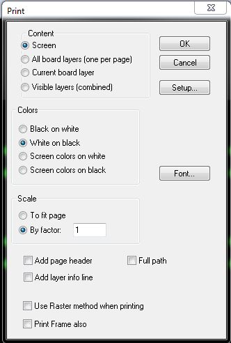
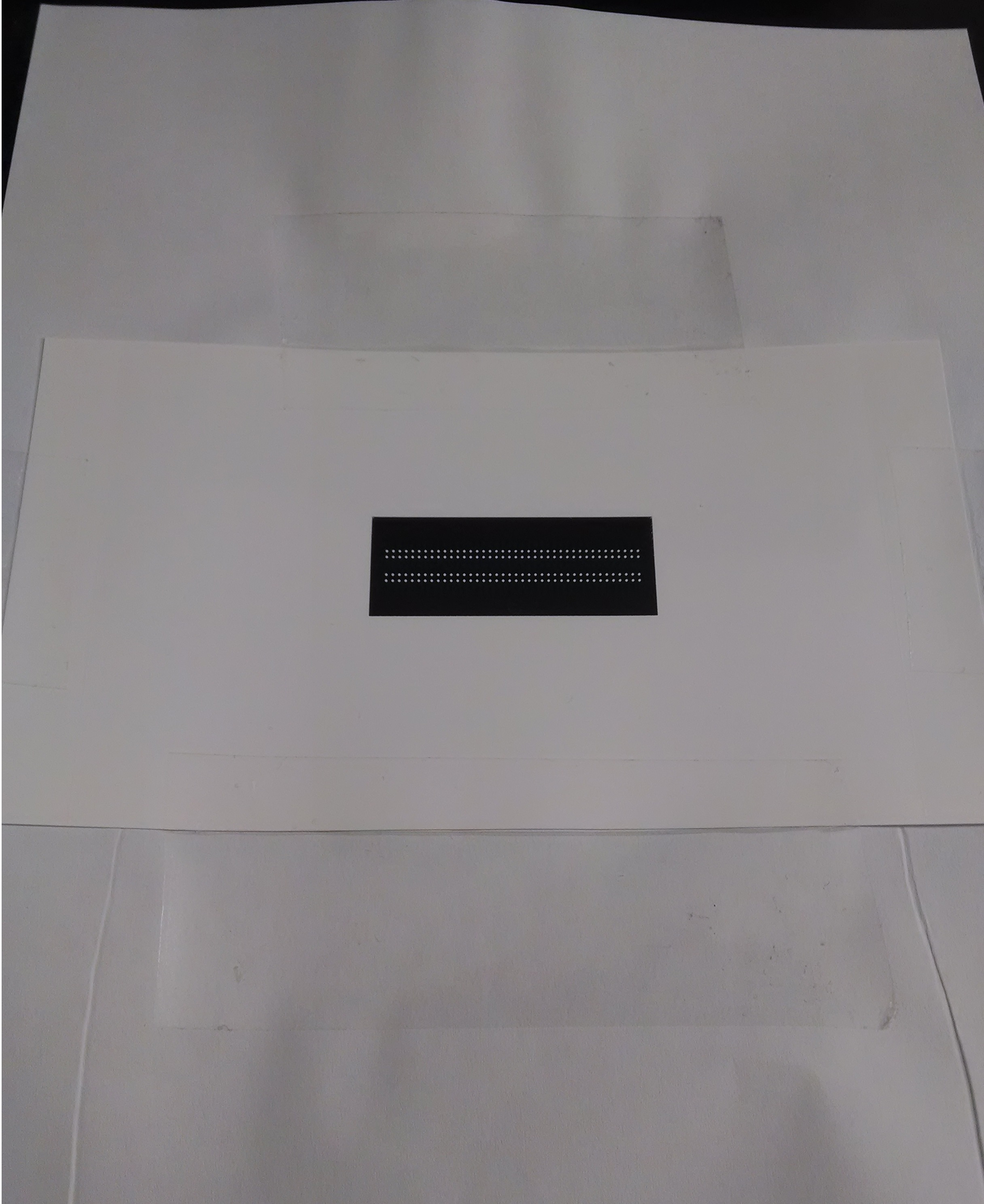
Now that we have edited the pads, we are ready to print out the design. When you hit the print button a dialog box will open with a few options. For the 'Content' selection you can leave it set for 'Screen'. For the 'Colors' section, select the 'White on black' option. This will give us white pads and a black background. In the 'Scale' sectioin select 'By factor:' and put a 1 in the text box. Then you can click ok and print out your design onto photo paper.
Make sure that you are using a laser printer! An inkjet printer will not work for this design!
Preparing Your Stencil Material
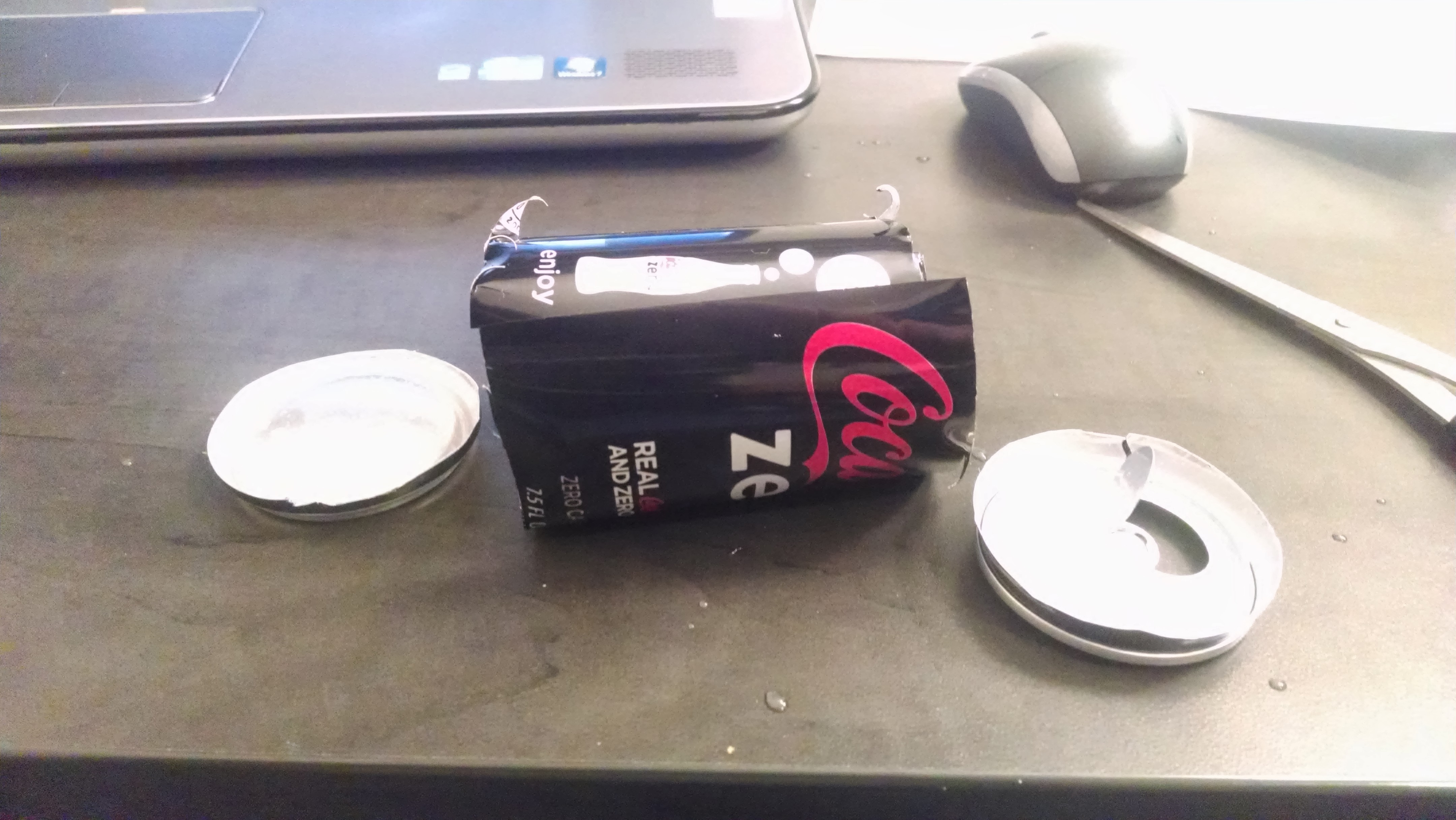
The material that we will be using to make a stencil is a recycled aluminum can that has been cut and flattened. To start off, reward yourself with a refreshing soda out of a can. After you have finished, rinse the can out then destroy it! We need to cut off the top and bottom of the can, do this carefully, using scissors or a knife. After the top and bottom have been cut off, cut down the side so that it can be unrolled.
When you cut the ends off of the can they tend to not cut very smooth. Due to this you will want to be sure and trim the edges after you get it semi unrolled so you do not end up cutting yourself.
Now we need to flatten the material as much as we can. I usually start by curling it in the opposite direction that it wants to bend. This will semi flatten it out, keeping if from curling up all the way how it was to begin with. Try stacking some heavy books on top of it over night or rub it on the edge of a table to get it as flat as you can.
Next we need to clean off the residues and ink that are on the can to allow to better toner transfer. This can be easily done with a little bit of acetone. You really only need to clean whichever side you are going to put your design on, even on the inside of the can, there are residues that need to be cleaned away.
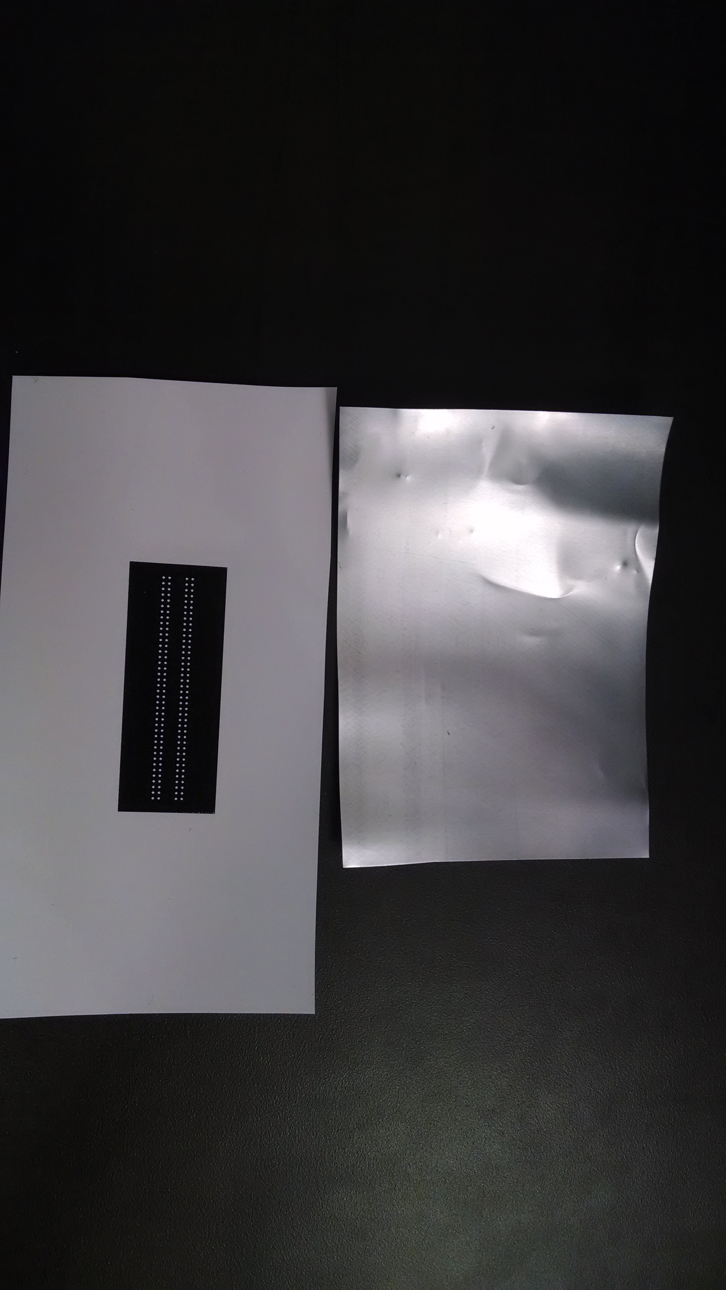
Once you have your can flat and clean, we can do a toner transfer of what was printed in the previous step.
Transferring the Image Onto the Can
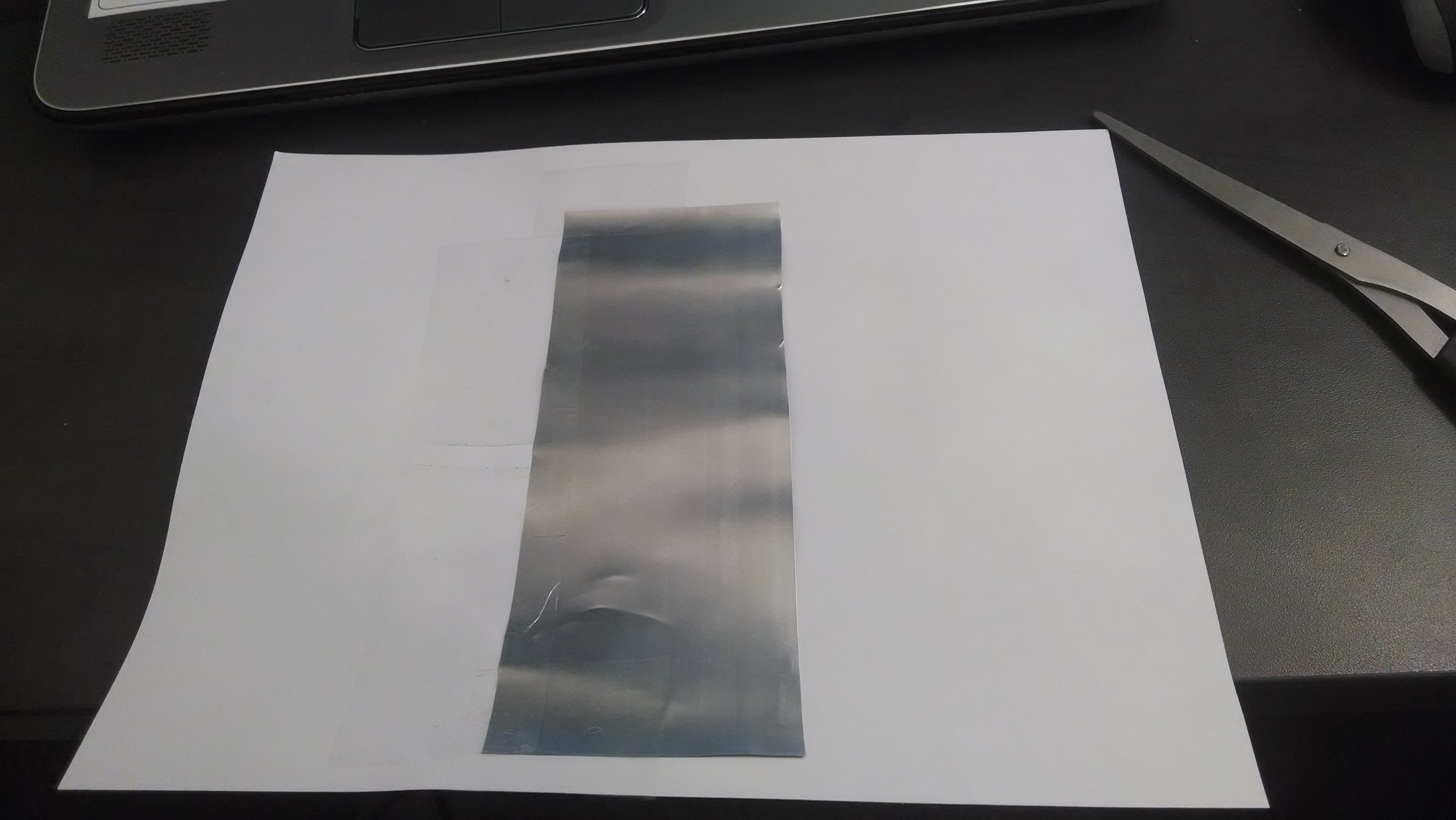
To get the image for your stencil on to the stencil material, you will iron it on the same as you can do for PCBs with copper clad board. Start by trimming the photo paper with your pattern on it so that you are not left with an excess amount of paper which could make it more difficult to align. Take a piece of scrap cardboard, like some from an old cereal box, and place it on an open work surface, this will keep you from scorching your table.
Place your flat can on top of this cardboard with a clean side up. Place your printout face down on the can and hold it in place with a little bit of tape on one side to keep it from moving while you iron it.
Turn your iron on to a high heat WITHOUT steam. Once it has heated up, place it on top of your print on the can and let it sit there for about 30 seconds, then apply force on the stencil for about 30 more seconds and repeat a couple times then check on the progress.
To check the progress, remove the iron and use a sharp knife or razor to gently lift up the photo paper and look at the can to see if all of the toner has transferred. If it has not then apply more pressure and check again. Continue until all of the toner has been transferred onto the can.
Once all of the toner has been transferred, you are ready to start with the etching process.
Etching Your Stencil
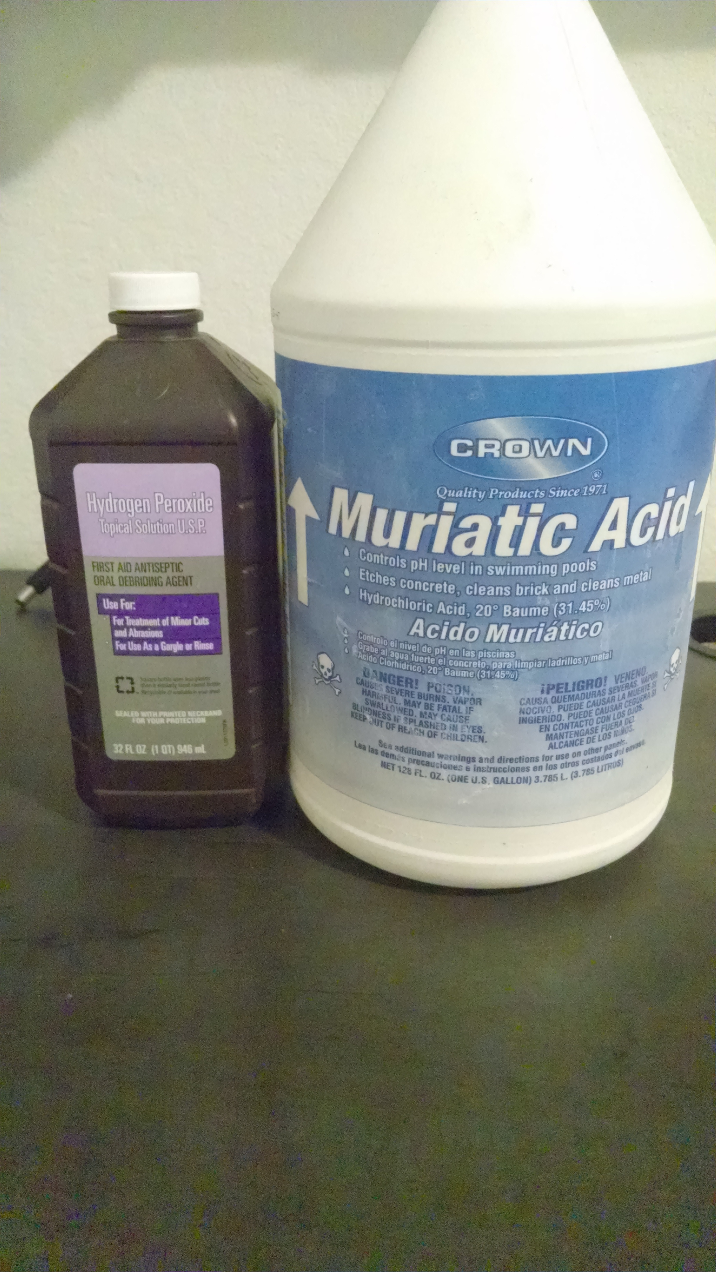
The solution for the etching process requires a mixture of one part muriatic acid and three parts hydrogen peroxide. I recommend wearing gloves while doing this and old clothes to reduce the risk of ruining a good pair or pants or a nice shirt.
Before you etch your stencil, you need to cover up all of the extra part of the can, the part around the toner, with the tape making sure that you don't cover up the pads that will need to be etched.
Once you have your chemical mixture set up in a safe container and your board all prepped, you are ready to etch. Place your stencil into the solution and keep a close eye on it. If you have a glass table and you are using a clear container it may be beneficial to put the container on the clear table so that you can look through the bottom of the table to see the underside of the stencil. This will allow you to know when you have fully etched the stencil and help you avoid over etching.
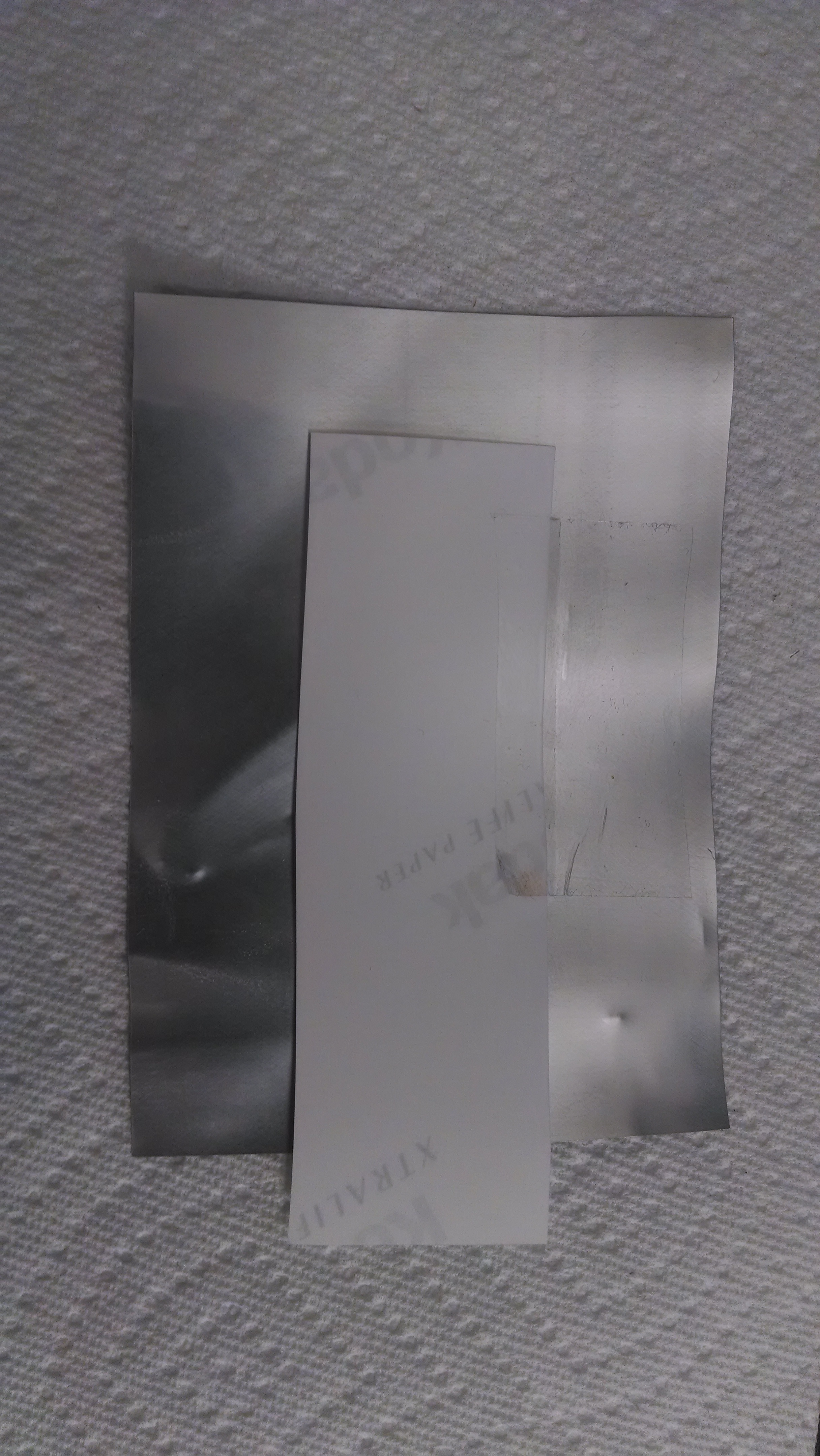
Once the stencil has been etched all the way through, carefully pull it out and rinse it off with cold water in a sink. Using nail polish remover or paint thinner, you should be able to easily remove the toner from the can.
You now have a completed stencil ready for use on your newest circuit board!