DIY Speaker Set & Amplifier: a Gift for Dad
by JavitoBosch in Workshop > Woodworking
7592 Views, 93 Favorites, 0 Comments
DIY Speaker Set & Amplifier: a Gift for Dad


Quick and easy summary of what you may encounter if you keep reading:
What am I doing here? I am building a speaker set with amplifier
Why am I doing it? There are a few reasons:
- This is a gift idea I had in mind for my dad, a tricky candidate if you want to gift him something special.
- DIYcling (Do It Yourself, Recycling), which means the implementation of recycled components/materials within your build. This means to me the fact of providing another life-cycle to 'a thing'. This involves reusing and repurposing.
- I love speaker design (amongst many other things)! This is yet another project that involves creativity, design skills, machining, electronics, problem solving skills and so on...
- I want to serve you as motivation for starting or continuing your (personal) projects. I am not expecting you to copy my project, as this is rather boring and nonsense. I would expect that you use my project as inspiration for yours, because in the end you need to add your 'magic', so the project will become special, unique, yours.
Don't forget to watch the introductory video!
How am I going to do this?
I do not want to show you (once again) how to build a pair of speakers. That is already shown in many other platforms. What I would like to show you instead, is how I managed this project from its concept until the finished product was ready to go.
Note for the reader: I managed to gather a considerable amount of footage. I am doing my best to edit and upload the videos just in time, but for now just pictures. And yes, they are in Spanish. They are especially made for my father, who prefers Spanish amongst other languages (I do not know why...). I managed to add captions in English for some of them, but there is another alternative if you want to read captions in another language. First, enable 'Subtitles/Closed Captions (c)', then go to 'Settings' -- 'Subtitles/CC' and select 'Auto-translate'. Choose the desired language and enjoy! I realised that this saves me a lot of work and you get a general idea of what I am showing here, since the translation is not 100% accurate. Well, sometimes the assistant just "spits" words and the whole thing does not make any sense. This is probably due to many factors (e.g. voice tone, sound artefacts/quality, pronunciation...)
More information about my projects: https://linktr.ee/javitosprojects
Supplies
I think the most important tools can be found within yourself and I consider them as mandatory:
- Will power
- Creativity
- Resilience
- Patience
- Optimism
Apart from the above, here you will find the corresponding project files (BoM, CAD, drawings, measurements, and so on).
Project Overview

I find very important at this stage, the fact of dreaming about a perfect product (everything is possible only if you make it possible). Write everything on a paper, draw diagrams and make nice sketches because you never know how many things you will end up using/doing. It is also good to experience your madness level (you will see mine in a few lines). Trust your judgement.
Project requirements
From the customer side (my dad):
- My dad is a simple guy, so whatever the outcome is, it needs to be functional and simple. Nothing fancy.
- He likes white colour.
- When things are made of real wood, he loves to display them as they are, natural and rustic.
- Sound-wise, I know he likes deep bass and sharp high-frequency sound. He is not an audiophile (me neither). Again, nothing fancy here.
From the designer side (my perspective):
- I do not like screws. If needed, they need to be hidden! The integration of screws in speakers is something that I still cannot comprehend as they produce a great visual impact that deviates your attention from other design features within the finished product.
- I do not want the amplifier enclosure to look like a (boring) box. It needs to have nice (simple) features, encouraging my father to display it.
- I wanted him to use the amplifier with any other sound system, therefore I will require a considerable output power and the possibility of adding a subwoofer.
- Repairability of the device must be good, so if it is modular and accessible, even better!
- We are in the IoT era, so full connectivity (WiFi, Ethernet, Bluetooth, Audio-in/out and USB-in).
- The speaker box must be a balance between performance and size, so they are easy to carry being able to be fitted in many places.
- The woofer should be no more than 4", so the internal box volume will be around 3L (this was a guess, although I used software to fine-tune everything)
- The tweeter must reach 20KHz with a good SPL [Sound Pressure Level]
- Sound equalisation is essential (we all appreciate sound differently) and must be done either by hardware and/or software.
- I would like to use recycled materials/components where possible
- I will start dealing with passive crossovers. Let's leave DSP-modules [Digital Signal Processing] for another project.
Project specifications
We know requirements, so lets define some specifications about the amplifier:
- I will use a Class D amplifier with 2x TPA3116, making a 2.1 system (~200W max). The board must have Bass and Treble adjustment knobs.
- Max power input <200W (10A@24V DC will do). A laptop power-brick could be used here.
- It will have a connectivity module. So far, the Up2Stream from Arylic is the perfect candidate.
- There will be 2 (independent) power supplies with their respective fuses. One for the connectivity board and the other one for the amplifier.
Overall, high efficiency, good audio quality, superb connectivity and modular layout that will allow me to keep a small enclosure size.
Now, the speakers + box. A 3-way system (Woofer - Mid-range - Tweeter) in such a small volume will definitely compromise the audio quality, so I decided to use a full-range driver in a vented enclosure, and a tweeter. I was hoping these two things would make a great combination:
- Woofer [W]: Dayton Audio ND91-4 (3.5") (More information in following sections)
- Tweeter [T]: Dayton Audio ND25TA-4 (1") (More information in following sections)
- The combination of natural wood and white colour must be present
- The frequency response must be rather 'good' at low frequencies [LF] and high frequencies [HF]
At this point, I had a little bit of an internal discussion (with my brain). Since I do not like (showing) screws, the drivers will have to be placed from the inside. How am I supposed to fit the drivers (W diameter is ~ 10cm) from inside, in such a little box (e.g. 3L = 14cm x 14cm x 14cm) that will be mainly glued? And what about the internal filling, the volume of the filter components and the vent size and location? Let's leave this for later sections...
Project timeline
This is not an easy part. You must consider delays, unexpected issues/challenges and a learning curve in some of the steps. Having this kind of overview helps you to foresee these things and to think ahead.
When am I planning to start/finish? I officially started on the 22nd October 2020 and had to finish by the 26th December 2020 (~ 2 months). I was expecting to spend and average of 2h on weekdays and 10h on weekends (~ 300h).
I had in mind that the amplifier would take most of the time and the speakers the least, but I decided to set a month for each sub-project (November for the amplifier and December for the speakers).
Since in my case I was a one-man-band, I expected to work on many things at the same time. They key point here is that time is crucial, so stay busy. These two sub-modules will definitely overlap.
Pre-work


This Step describes all the work needed in order to verify that I could start my project, being confident that it can be finished:
Brainstorming
At this point, you know what is going to be inside the 'boxes', but what remains unknown is how the product is going to look like, its reliability and if there are any possible upcoming challenges. Here I was looking for a feasible project outcome. You do not want dead ends. Questions I had in mind for a long time before even drawing a single line:
How are the enclosures and amplifier going to look like? What about manufacturability an assembly? Can I make them at home with available tools? What kind of innovative features am I adding in order to make a unique project outcome? What materials am I planning to use?
DIYcling
There are many things (let's talk in general terms) that we (the human kind) discard everyday because they have been qualified as old fashioned or waste (you do not want them within your premises anymore). These things still work most of the times and can serve for longer than you expect with minor repairs (e.g. repurpose, reuse), but why are you thinking about this if there are tons of (new and up to date) things out there that you can (just) buy? Well, have you asked yourself where does the waste you generate everyday end? Probably, in the middle of the ocean between all the fish we will later capture and eat. Now multiply this times the number of humans living on Earth. It does not look nice, right? Yes, common sense.
To recycle, to reuse, to repurpose are not a practices. They are mindsets that must be embedded on each of us. Short and simple: one day there will be more waste than nature if we (humans) keep living this way. As of today, there is only one Earth.
DIY and recycling should hold hands tight (DIYcling). I decided to implement this mindset on my first build and I am sure we are loads of people already doing that, but not everyone. This is to a certain extent, because there are things that I could not find or that I already had available from other projects. Of course, this practice involves more work and challenges that I am happy to go through. What I surely decided to reuse:
- Wood: the main idea here is to buy a second-hand old fashioned shelving unit (ideal for this project) or similar, disassemble it and give it a brand-new life!
- (Electronic) components: as for now, I know that I have plenty of switching power supplies (e.g. phone chargers, laptop power bricks, etc.) laying around, wires and connectors from other projects. In addition, the vent for the speakers was an old (never used) PCV drain pipe.
You can add as many as you want in your build.
Who was first, the egg or the chicken?
I spent quite good time thinking if I should start designing with a certain wall-thickness of the used wood panels, or buying/getting the furniture first and then start designing and I remembered that "the only way to learn how to swim is swimming", so jump to the pool! In other words, get the furniture first and have in mind that the simpler the better (no funny shapes or ornaments) as you will be able to use the most of it. Also, the least options you have, the more creative you will become (I absolutely adore that). Check the media files to see what I luckily found! Yes, heavy oak panels for a few coppers, just perfect.
My personal touch to the end product
I could imagine my dad really doubting if I reused furniture or not within my build, so I decided to create a QR code with a message "I used to be..." embedded or sticked in the wood. Once my dad scans it with his phone he could actually check that his brand-new speaker set was part of a different furniture not long ago. Well, more on this topic at a later stage...
Something I was thinking about is a product name, a personal signature. I do not like brands that are the product show off. I prefer to say that products are signed. I decided to call these speakers echoBlues. Brand name is Blues and product segment is echo. I used to have a guitar pedal effect board, the Boss ME20. I really likes using the Blues distortion effect with a bit of reverb. When playing with reverb is like being in a room with echo, right? I thought that echoBlues sounds catchy and better than reverbBlues...
Do I have all the required tools for this project?
We often start designing without even knowing how a certain component can be manufactured and/or assembled. It is hard to know beforehand the tools required for a specific project, but at least you can elaborate from basic machining operations you will be performing. In my case, I thought of:
Cutting - mainly table saw and jigsaw
Drilling - column drilling machine and hand driller
Milling - router machine (preferably, a router table)
Sanding - rotary sanding machine
From the above, I can say I had almost everything but the router table, so I made a simple and reliable one made of marine plywood. I wanted it to be very flat, with a smooth top to prevent any product damage, a straight guidance system and 'vibration-free' supports (picture attached).
In addition, I built a wooden platform for cutting wood with my table saw. The panels I managed to retrieve were hard to manage and I love my hands, so I created an "H-shape" clamping tool (quick and easy solution).
Last but not least, I wanted to check a few more things: how the wood would look like after an oil finish, a backup plan just in case I did not like the result (e.g. a different wood type, like acacia) and how the drilling bits would perform. Check the video for more info.
By this time, I thought I was ready to start! If you are still there, go to the next Step!
Amplifier Concept Design and CAD Modelling

Concept Design
I believe that for the concept design is ideal to make some sketches in a paper while making a CAD (Computer-Aided Design) model. The sketches will contain what you imagine right away, considering component measurements. The CAD model will be used to confirm that there will be no conflict between what you imagine and reality.
At this point, I already started buying components or simply making measurements from what I was finding online that I really liked.
Main concerns
- Wood: as you may have seen in previous video, the wall-thickness of the wood panels was 20mm and if I wanted to fit the rear connectors of the Up2Stream or the front potentiometers of the amplifier, then I will have to reduce the thickness from 200mm to 2mm! How am I planning to do that at home?
- Inner structure of the amplifier: I wanted to be able to slide the electronics in and out of the outer case of the amplifier (already shown previously). The drawer runners I found were HUGE, so I decided to go for magnetic levitation with permanent magnets (yes, my brain was whirling). I could also use a simple 10x10mm wooden strip, making a friction-based system leaving a lot of wood dust every time you open the amplifier. Wait...how many times are you planning to open the amplifier during its lifetime? Don't keep reading, just watch.
Amplifier CAD modelling
This part will give you the confidence needed in order to start manufacturing. You should be able to determine if your project can be manufactured and assembled, resulting in technical drawings with manufacturing/assembly tolerances. Few comments:
- I was working on many things in parallel (like I mentioned before), so I was recording when I had the time and therefore you will hear me talking about things already made, but no worries, I am trying to synchronise everything, so it makes sense to you.
- CAD modelling is a very useful tool that can drag your progress considerably. It all depends on what level of detail do you want/need in your model. I would suggest you create all details needed for the manufacturing and assembly verification of your product, saving loads of time while making a functional model. For example, modelling electronics is just a no go for me. I prefer to model volumes, so I can foresee any potential assembly volume conflict. However, the amplifier inner structure and the housing need to be modelled to the very detail, considering all your available tooling (e.g. milling bits, drilling bits, saw blade thickness,...) and having in mind that you will be machining all of these components.
Amplifier Inner Structure and Housing


Amplifier Inner Structure
What is the main functionality of the inner structure of the amplifier?
- To keep the electronic hardware in one place
- To support the rear cover of the amplifier housing
- To be easily disassembled (e.g. for repairing or replacing components), so no glue and the least amount of screws as possible
- To keep all hardware at a nice temperature
Requirements:
- Super-accurate (within 0.5mm) overall width and length of the assembly was needed. The offset with respect to the amplifier housing was 1mm (0.5mm each side). It ended up being within 0.6mm (great!)
- Perfectly squared sides and top/bottom levels should be quite parallel. The trick here is to choose reference planes that are considered as perfect.
About the outcome:
I ended up with a pretty robust structure, easily assembled with 8 countersunk screws. Funny fact, I could easily place 40kg of weight and it was holding it like nothing happened. I will keep it in mind for future builds, since the little recessed features (steps) are the key for this build.
I first tried to use the back panel of the furniture I bought. I wanted a thickness of 8mm at least, something that I could achieve by gluing the two halves of the back panel. However, once I finished making the structure, I realised that I should have trimmed down the excess using a file instead of cutting with the jigsaw as accurate as I could. Therefore, I had to use some 9mm plywood I had in the workshop since I did not have reusable wood anymore. The look of both outcomes is just amazing.
This took me a total of 2 iterations: first, I made mistakes when making the different interfaces; second, I realised that the back cover panel would need extra support but I did not have to remake everything again. You can see both outcomes in the pictures.
Unfortunately, I don't have any video about the making of the inner structure of the amplifier.
Amplifier Housing
In a few words, I encountered many many challenges and I made uncountable (beginner) mistakes. However, what is more important, I managed to find a way around! At this point I would recommend you to watch.
What really helped me was to write down all process steps needed in order to successfully machine a part (e.g. the side cover of the amplifier housing). This way, I could forget about thinking "what is next" and also spending extra time verifying everything once again. It might be a bit silly, but this boosted my personal confidence levels.
Challenges
- Guidance system for the inner structure: I spent a whole day trying to cut 1cm x 1cm wood strips in order to create the guidance system. The outcome is just as I expected. It was worth it!
- Top of the amplifier: the venting slots were not a good idea and I ended up breaking the part by mistake as the links were too weak. Reducing the thickness from 20mm to 9mm was not satisfying. A lot of wood dust, a waste. However, lesson learned for the future.
- Gluing the amplifier housing: what a stressful process! I only had one chance to glue all parts and keeping clearances to the limit. Here I realised the importance of high-quality tooling (in this case, custom).
- Amplifier Front and Back cover: reducing the wood thickness from 20mm to 2mm was a challenge with the available tooling, but with a lot of patience and bit by bit it all came together first time right!
Amplifier Electronics


Time for electronics now that the inner housing is ready! I would like to focus on the most important thing: the amplifier module. Te rest I guess you can get it from the video and if not, feel free to ask me:
Design requirements
- How much power does this amplifier require? This number is based on the speaker driver's RMS (Root Main Square) power requirements and can be found on the manufacturer's data sheet. By RMS the manufacturer specifies the nominal power that the speaker driver will demand from the amplifier in order to function. Now, we have 2 tweeters and 2 woofers in this system and the possibility of adding a subwoofer, so 3 channels in total. The TPA 3116 data sheet should be showing the output power (voltage and current values too) that can be delivered. First, compare if the sum of the RMS values of your drivers for one channel will lay below (ideally) or equal to the power values specified by the manufacturer. Then do the same for the rest of the channels. Don't forget to add a performance ratio and you will calculate your power requirement values! Or at least the most significant part. In my case, 200w were required.
- Why a 24V power supply? The data sheet specifies a range between 4.5V to 26V that can be supplied, being 21V the recommended value. I could easily find 10A@24V power supply units and I decided to set this one as my baseline.
- Why two power supplies? One is for the amplifier module and the other one for the connectivity module. This way, you avoid any disturbances that can be appreciated through the speakers (e.g. buzzing and chops) if only one power supply and a step-down voltage converter is used.
- Is there any safety? By default a power supply should come with protection. However, I decided to add an in-line fuse for each power supply, just in case.
Final specifications:
- Two power supplies were purchased for the amplifier module: 10A@24V (max) and 9A@24V(max). I did run "some tests" (Step 6 for more information) and the second option was the winner from every single point of view.
- Connectivity: Up2Stream Pro V3 from Arylic. Great board with all the connectivity I wanted, so the amplifier can stay up to date and many other devices can be paired, making use of it. This board was placed at the rear of the amplifier and therefore I had to remove all LED indicators and the IR sensor to the front.
- Second power supply for the connectivity module: this was a fake (working) iPhone charger I found in the street, 2A@5V (max)
- Amplifier module: essentially, two TPA3116 in parallel that can make a 2.1 system out of it. I was fooled thinking that it also included treble, bass and balance adjustment (pre-amplification) and I was completely wrong. What was labelled as treble only adjusted the volume of that channel, in this case the speakers. Hence, what was labelled as bass only adjusted the volume of the subwoofer channel (if plugged in). This is the downside of buying cheap electronics, although the amplifier has been performing very well since the first run. However, foreseeing this, I could rely on the (digital) equalisation from the connectivity module (at least something). All potentiometers were re-soldered on a separate board, so I was able to place them where they should be in the amplifier.
Lastly, I felt the need of verifying what the manufacturer was claiming about both power supplies. I have to admit that I was very suspicious from the very beginning. Do you want to know more about it? Next Step!
Power Supply Tests


Why a dedicated step for this component? Well, this is the heart of your amplifier. If the heart is in a bad shape, then there will be little or no boom boom. Since I was ordering parts from Aliexpress, I really wanted to make sure that nothing would blow up on other's hands. Bear in mind that we are talking about 216w.
Perhaps my methods were not the most appropriate ones (feel free to comment), but they helped me when deciding which power supply was more reliable for this job.
WARNING: only perform these tests if you know what your are doing. Electricity in wrong hands equals to dead. Do not leave any kind of test running unattended as there is a high risk of accident, damage and injury. I hope that I am clear.
Testing circuit and summary slides in the pictures section!
What kind of test did I perform? Test criteria
- Aim: to prove that each power supply can cope with a load equal to its maximum specifications for a certain time and if there is any risk of fire given that the amplifier is made of wood.
- A total of 4 tests will be performed per power supply
- Each load is a set of power resistors connected in series (from ~2.5 to 6 Ohms), forcing the power supply to provide a certain current.
- Measured values on each test: voltage, current and power before (AC) and after (DC) the power supply (yellow in the picture); temperature values. A thermal picture is also taken for aded value.
- Measured values will be done at t=0. This is because after a certain time, the value of the resistors will increase due to the heat dissipated and the test will be no longer reliable.
- Calculated values on each test: theoretical values of current and power based on a constant 24V supply and ideal resistor values; real provided power in DC and performance ratio (green in the picture).
- Overload circuit test: each test will last between 3 to 5 minutes (the more the output current, the less testing time) in total as I wanted to see if any circuit protection would be triggered.
- Tip: Electric power will be dissipated in the form of heat for each test, so it is good to wait between tests until the hardware cools down, keeping the same test conditions.
Conclusion
Another amazing stage in this project. It was a pretty "hot" experience that allowed me to determine which power supply was the ideal one for this application. Of course, I did try things like reversing polarity and a 1-Ohm resistor to trigger the protection circuits. It all worked fine in both tests and I was finally happy.
Amplifier Final Assembly


This is the time in which literally ALL comes together. This is stressful, but exciting! Watch, watch, watch! I was extremely happy with what I achieved...and it was working!
Speaker Enclosure Manufacturing and Assembly


Concept Design and Modelling
- How did I acquire the basic knowledge? I did a training course by Rochester University via Coursera 3 years ago, so I roughly know the theory behind the enclosure design and much more, since it is rather technical (I like it). I also combined the training with a book: "Introduction to Loudspeaker Design" by John L. Murphy (basic but straight forward). I also followed a YouTube channel, Impulse Audio as this helped me to foresee the applicability of what I was learning from a DIY point of view. Finally, I also followed a blog, Audiojudgement from Marius Tanasescu.
- Why did I choose the ND91-4 (3.5") and ND25TA-4 (1") drivers? The woofer is a full-range with a high cone excursion, which helps in the low-frequency range with such a small size, making it ideal for a small volume enclosure without giving away sound reproducibility. The tweeter had a rather good response on the high-end, making it suitable for this application. I also liked the grid, since tweeter domes are very prone to be easily damaged.
- Why a ported speaker and not a sealed speaker (Efficiency Bandwidth Product)? Very briefly, this is a value that works as indicator in order to determine if a sealed/ported enclosure is the most suitable option for your main drivers.
- Why is the vent located at the bottom of the speaker enclosure? Because this way I could tune the length of the vent to a lower frequency, making it longer if compared to the front/rear (ugly looking) location, allowing me to use a smaller box volume while using the larger of the dimensions (box height) for the vent. You end up with a rather optimised and compact speaker enclosure volume. Now, the vent is not inline (vertical) with the woofer voice-coil actuator (horizontal) and you may wonder if there is any impact in the dynamics. Well, air is acting as a spring and needs a way to escape. Gravity could influence the dynamics (even help in this case!) but I honestly did not have the time to evaluate this. Anyway, this is nothing new. I remember reading about it from Bowers and Wilkins if I am correct.
- How did I find the optimum enclosure volume? Short answer: the manufacturer's data sheet already specifies a commended enclosure volume for a certain driver. However, in this case I was using a tweeter (usually neglected) and a woofer, so I also wanted to consider their internal volume with the addition of the internal volume of the crossover and the vent. I ended up using available software, like VituixCAD (amazing) and/or WinISD. The first one still gets regular updates whereas the second option does not. It is good to have both of them, just in case. You will find your preferred choice with time. With respect to the speaker box volume (Vb), I found out that ~3L will be the optimal volume, reaching a box frequency (Fb) of ~70Hz.
- Which alignment did I choose and why? Well, this comes down to the kind of response that you want to achieve. In my case, a bit of a boomy response on the low-end and spiky on the high-end. I guess now you see why knowing the customer's preference is a must in this business. However, there are tons of audiophiles out there, aiming for a perfect flat response through the entire frequency range. For the rest, Marius did a great job explaining it. It is a pretty long topic, though.
- What about sound dampening? Yes, this is about standing waves or enclosure resonance (unwanted/unpleasant noises and vibrations while you are listening to music). The aim here is to change the internal shape of the enclosure so these waves can be avoided/mitigated. On one hand, you can use filling material that will absorb these waves and will virtually make your box slightly bigger in volume (~10-20%, material-dependant). On the other hand, I believe you can change the internal geometry of your box, creating the same effect and therefore contributing to the wave diffraction. Hence, the multiple circles I created with different diameters and depths (see pictures). Again, I think this is nothing new and my guts feeling tell me that is the right way to do it. Do I have any results proving that this works? Not for now, but I am planning to make a comparison in the future.
Manufacturing
- No screws. Hide them somehow! I don't like the look of screws and I love a simple and plane (nowadays, minimalistic) front view of the speakers. Of course, no grid and plane wood with the best texture as a show-off (you want to have them seen in your living room!) and oak was ideal for this. I had to place the speakers from the inside, forcing me to make a (beautiful) countersunk transition between the front panel and the speaker. I also had to remove material from the inside, always thinking about internal volume gains while keeping the enclosure size as reduced as possible without compromising sound quality. Nice challenge.
- How to assemble the speaker box? top, bottom and sides were glued but the front needed to be detachable, otherwise I don't know how would I have placed the speaker drivers and the crossover. Therefore, I decided to design a clamping mechanism that would allow me to slide the front cover from the bottom using a keyhole feature. In short, this feature is the same one as it is created in picture frames if you want to hang them from the wall with a screw. In this case, there were four of them in order to achieve a leak-tight fit.
- Finishing. I used oil for the front panel, and the rest of the speaker box was painted in white with a water-based furniture lacquer. Of course, loads of sanding was needed and a base coat/filler too.
Challenges/Issues
- Creating features on the inside of the speaker box in order maximise the internal volume, while keeping the same external volume was a challenge. Bear in mind that dynamics (structural stability) needs to be considered here (e.g. excessively thin walls will undoubtedly affect sound performance). I love these kind of challenges.
- Keyhole clamping mechanism. Yes, I did go a bit too far on this one, but it worked. The problem here is the mating interfaces, They need to be perfectly flat in order to create a leak-tight assembly. I did not achieve this at first because I tried to achieve the final results when cutting/trimming the wood, rather than sanding/grinding. I ended up applying glue on one side (enclosure) and tape on the other side (front cover) while clamping everything. Once the glue is dry and the tape is removed, what is left is a smooth surface that has filled any kind of imperfections and allowing me to achieve a leak-tight assembly. I also had a little situation in which the keyhole bit got loosen while I was machining, making an almost thru-hole that later I had to fix.
- I made uncountable mistakes while machining (e.g. the little holes in the front are not done on purpose although they look nice), making the key holes and painting (I used a very thin brush, but I was looking for a sprayed lacquer effect). None of these set me back and I made notes for my next build!
Speaker Box Electronics


Many call the crossover design an "art", since it will impact the audio quality/fidelity of your speakers. I will be more specific with my next build, since one can easily write an Instructable about this topic. Important information:
- How did I acquire the basic knowledge? I did a training course by Rochester University via Coursera 3 years ago, so I roughly know the theory behind the enclosure design and much more, since it is rather technical (I like it). I also combined the training with a book: "Introduction to Loudspeaker Design by John L. Murphy (basic but straight forward)". I also followed a YouTube channel, Impulse Audio as this helped me to foresee the applicability of what I was learning from a DIY point of view. Finally, I also followed a blog, Audiojudgement from Marius Tanasescu.
- General aim: to obtain the flattest response as the system can allow. I agree, if this is what you are looking for.
- Basic rule: the least components, the better, the cheaper and less audio processing that will happen. At the expense is how well the drivers will reproduce a certain sound-wave (how well a speaker will perform). Crossovers can get really, really expensive.
- What do I need? You need the impedance files of the drivers (manufacturer or measured) and the near-field measurements.
- How do I get the measurements and what program did I use? Marius has a pretty straight-forward, yet practical explanation about the process that is followed (and how to not to design a crossover). I used REW for obtaining all measurements.
- Why not an active crossover? Because I am a beginner and I wanted to go through the process.
- Does a full-range driver require a crossover? I don't think so. The aim was to use this full-range driver as a woofer, being capable of pretty good performance on the low-frequency range, with a rather low natural frequency. For the high-frequency range a punchy tweeter. Therefore, I need a crossover to differentiate (filter) and dedicate highs and lows to the corresponding driver.
- How did you design the crossover? I used XSim although you can use VituixCAD. XSim is simple, intuitive, light and does what it is meant to do. I started by placing the drivers and loading the impedance and response files. I connected a virtual amplifier with no passive components and ran a simulation. Once I checked that the files were correct, then I disconnected one driver and decided to focus on the tuning of only one at the time. Lastly, you merge both responses and proceed with a final tuning.
- I decided to go for a 2nd-order crossover. Why? Because it was performing slightly better than a 1st order. Frequency response graphs are not the only important ones. Power, phase, impedance, excursion, air vent speed, delay and many more should be checked prior to choosing a crossover network. I dedicated many hours to this job as the outcome would seriously affect the overall sound performance.
- I have finished, now what is next? You should perform measurements again in order to get the overall system response, verifying that the result is what was expected. Usually, a near-field, far-field, cumulative spectral decay are some of the tests that can be performed in order to obtain a plot of what a speaker is capable of doing and how well it is doing it. Think of this as if it was the power graph of a car after upgrading many of its components.
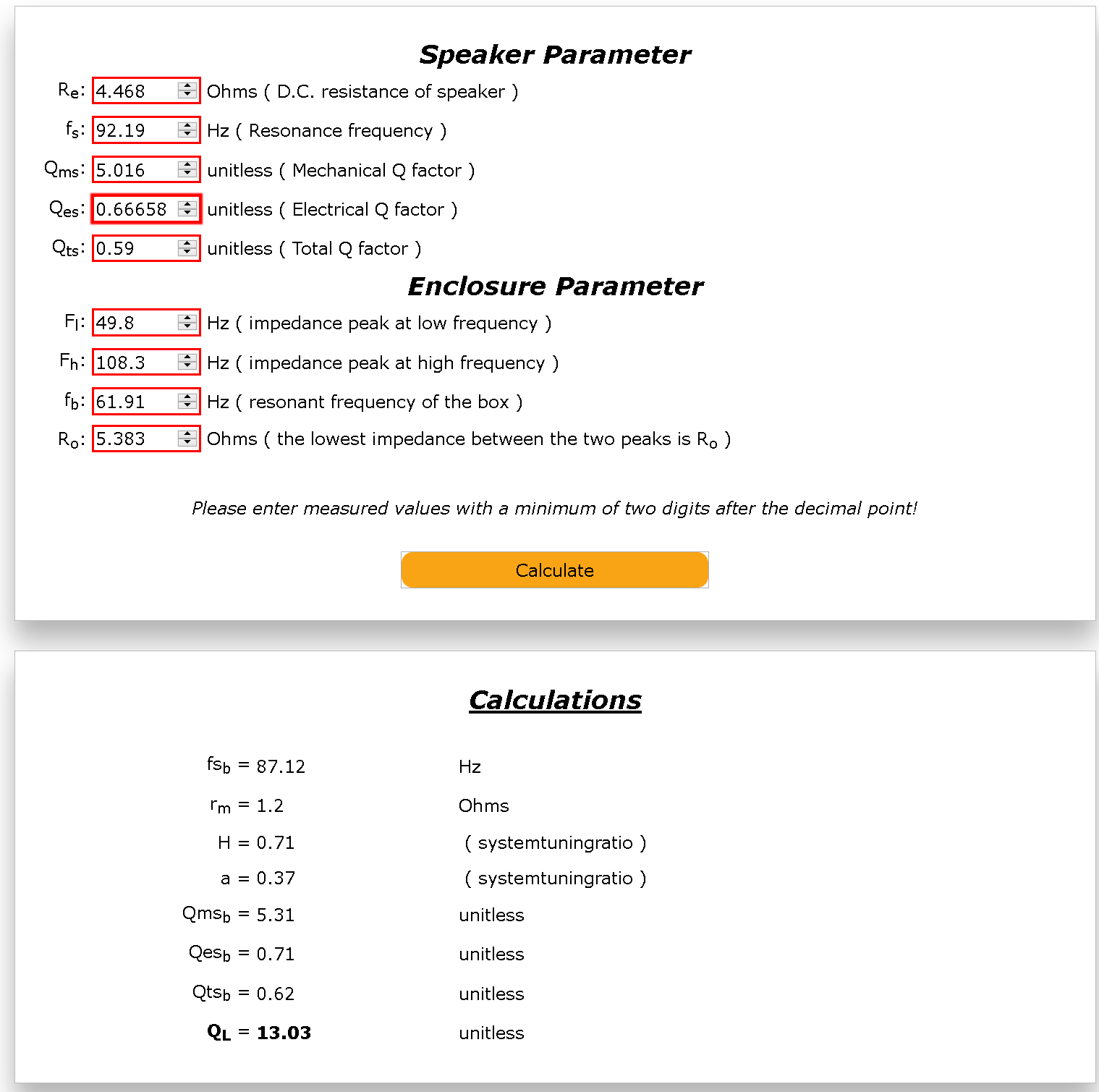
- How do I check if my speaker enclosure is leaky? There is a parameter, Ql that measures the leakage of your woofer in a determined enclosure based on measurements. There is a simple online calculator, so I decided to use the measured data in order to see how leaky my boxes were. This is having in mind that one of them was not properly secured, since I just fixed one of the fixation points as I already mentioned in the previous Step. Values were between 10 and 13, so less than 20, more than 5 and very close to 7 (standard value). The webpage also includes a very clear explanation about the meaning of these values.
The final result
I did not have time to perform any measurement after installing the filters, but I could tell from the audio (playing different tracks) tests that these speakers were performing amazingly well. I could tell by how well the highs and the lows were differentiated and how little distortion could be appreciated when the volume was considerably raised.
Usually, filters are assembled on a separate board and then this board is inserted inside the speaker box. In my case, available space meant luxury, and therefore I decided to use the available space on both sides of the venting. All components could be fixed to the sides/bottom panels with some hot glue. I was always placing part of them against the bottom of the speaker, just in case the glue melts due to the excessive heat (it may happen).
Le Grand Final


(It looks like YouTube did not like the audio I used in the last video due to copyright issues, even though it is just to 'show' other that the speakers perform well. You can get the original clip from here)
My father was speechless. I am so proud of being his son. You cannot imagine. I told him: "this gift was only possible because of what you taught me when I was a kid. Thank you."
Of course, this sounds weird when you don't know what is about to happen. He looked at me thinking "why did he get so sentimental all of the sudden?" and I gave him the remote controller for the Arylic Up2Stream. "This message and now a remote controller?" I clearly got him in the spot, because he could not expect what came next...
And a year has passed since the moment I decided to build this unique piece of hardware. Recording, editing, sorting out media and writing has taken almost 10 months (with ups and downs). Yes, it is not perfect, but it is REAL.
I am glad to report that I can consider this project completely finished from A to Z. Peace of mind for the master.
I could have done tons of things better, but that is why we make mistakes. We need to learn how to not to do things!
I hope this build motivates you not only to build things and feel proud of yourself, but to keep growing as a human being. You are capable of doing/making unlimited things, because you will achieve anything you want in life but only if you want to.
See you on the next build, because there will be more and better.
Javito