DIY - Smart Walking Stick for Visually Challenged Using Arduino UNO
by Niltfig Nakamoto in Circuits > Arduino
2787 Views, 3 Favorites, 0 Comments
DIY - Smart Walking Stick for Visually Challenged Using Arduino UNO
.png)
Technology can neutralize human disabilities
With this in mind, let us leverage the power of Arduino and basic sensors to make a Blind man's stick that can help visually impaired people to walk with confidence avoiding the obstacles found in front of them.
Supplies
.jpg)
.jpg)

.jpg)
Materials Required:
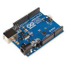
- Arduino UNO
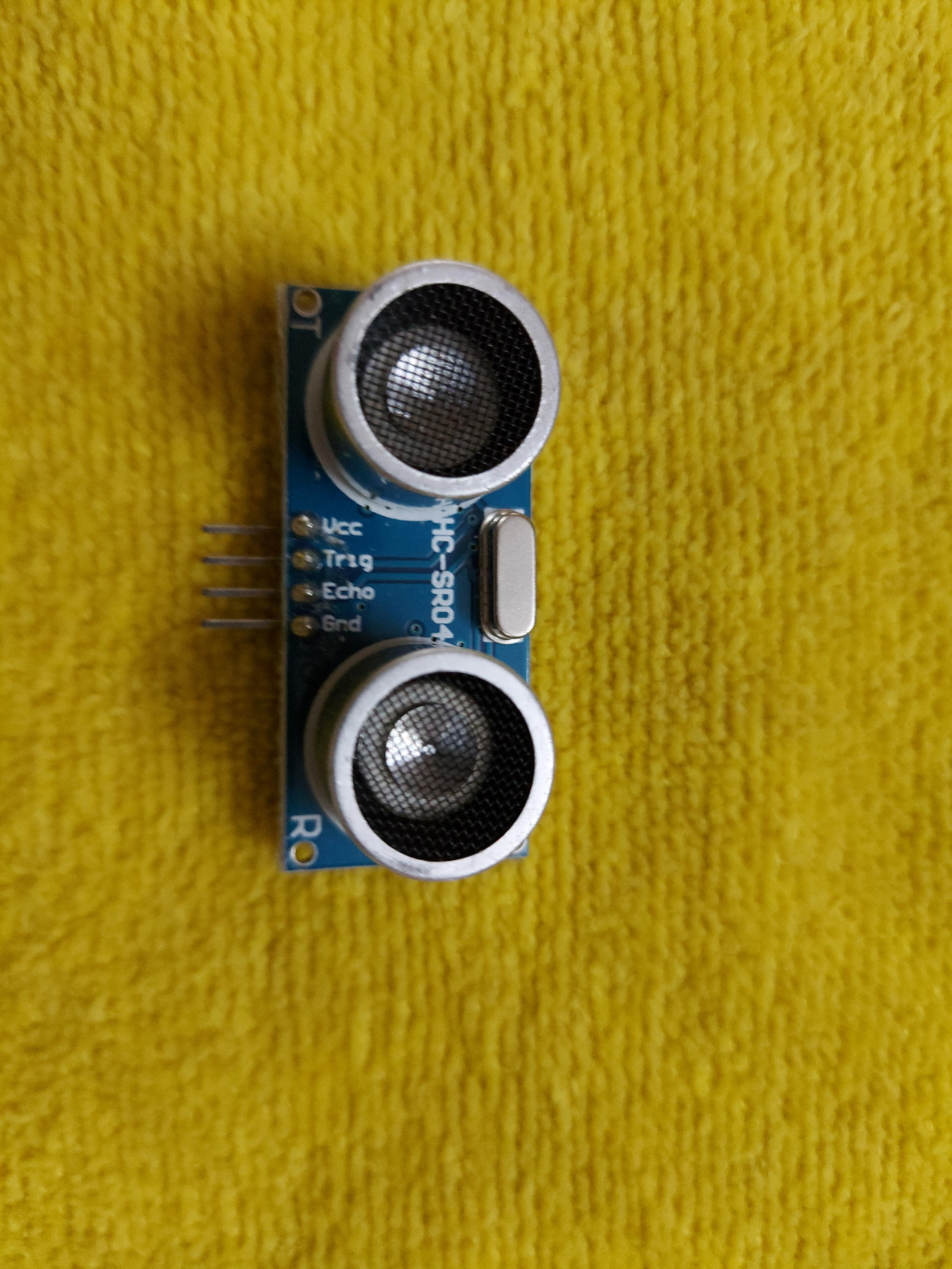
- Ultrasonic Sensor (HC – SR04)
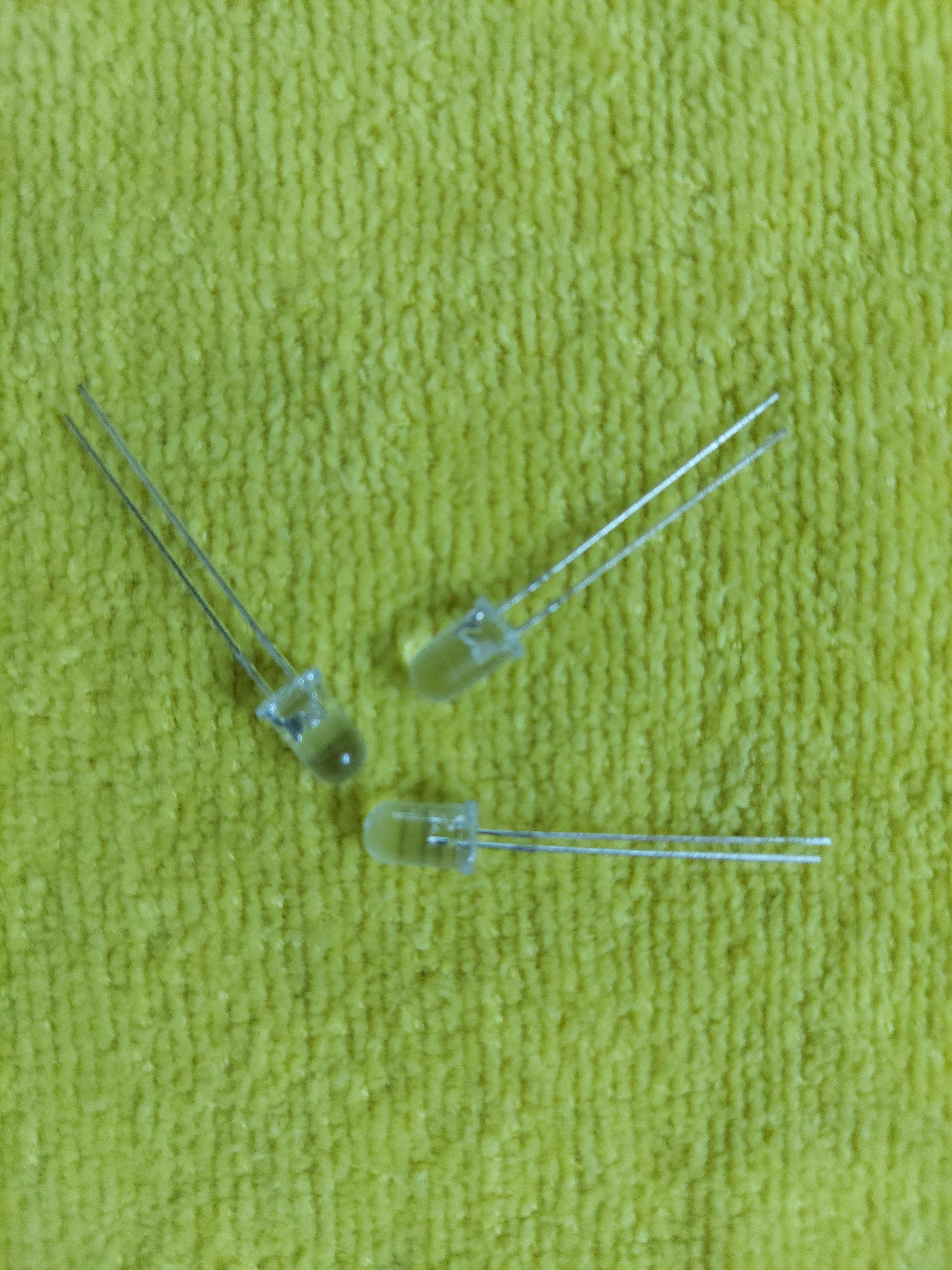
- LED
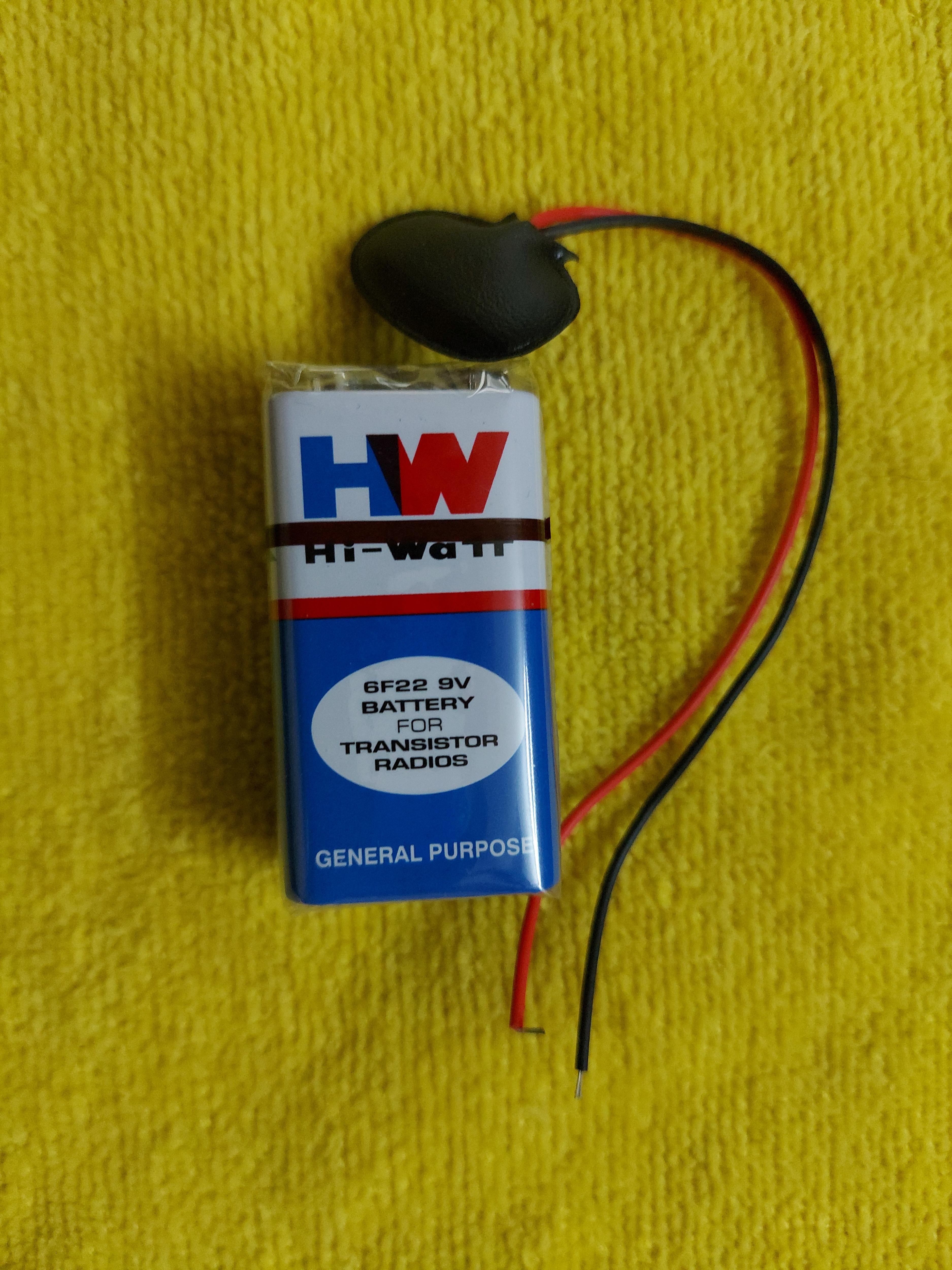
- 9 V Battery with a connector
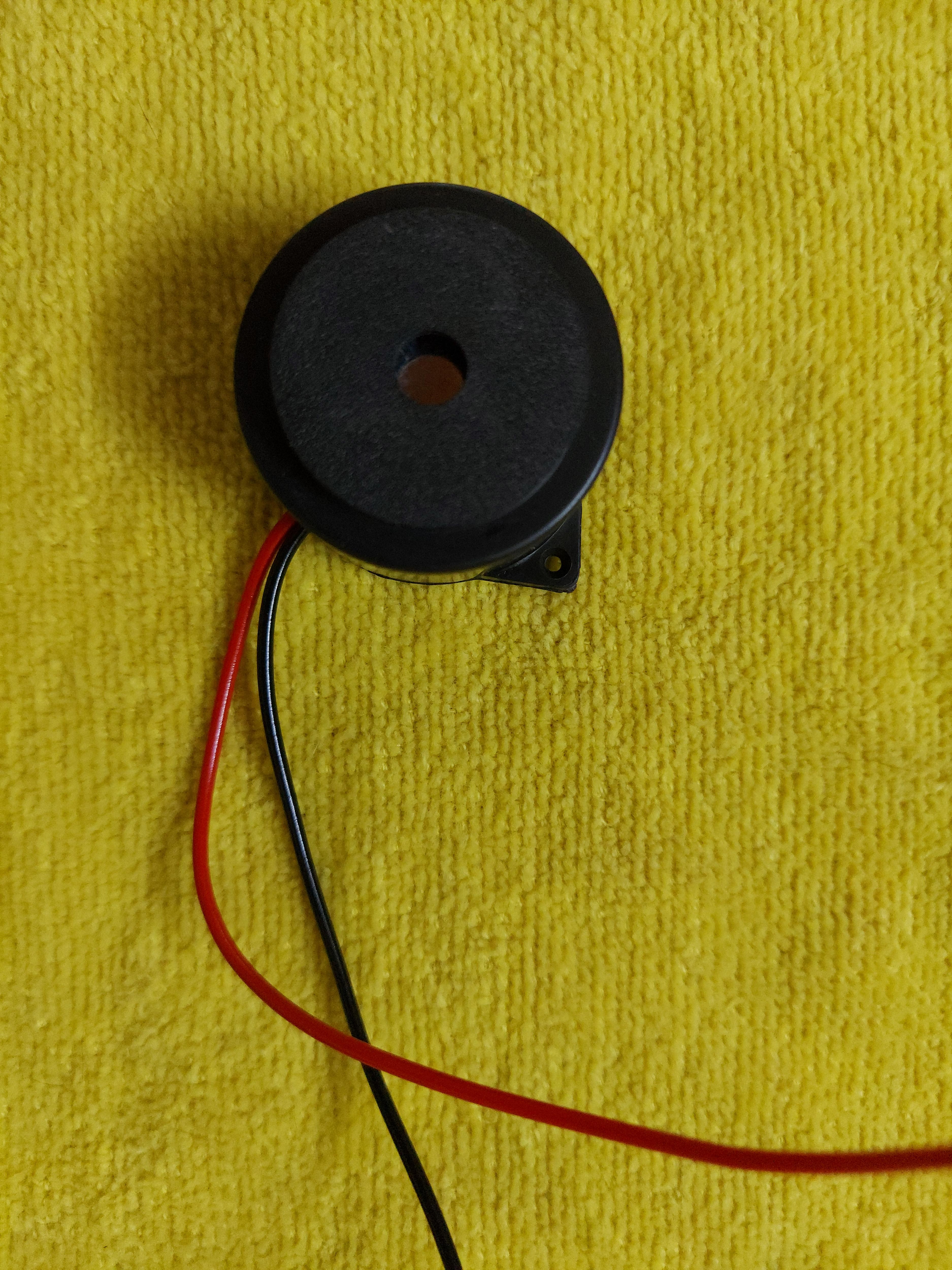
- DC Buzzer
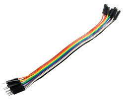
- Jumper Wires
- A PVC pipe or a Walking Stick
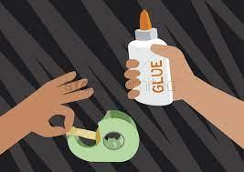
- Tapes and Glue
Making Connections With Arduino
.png)
Let's make the connections!
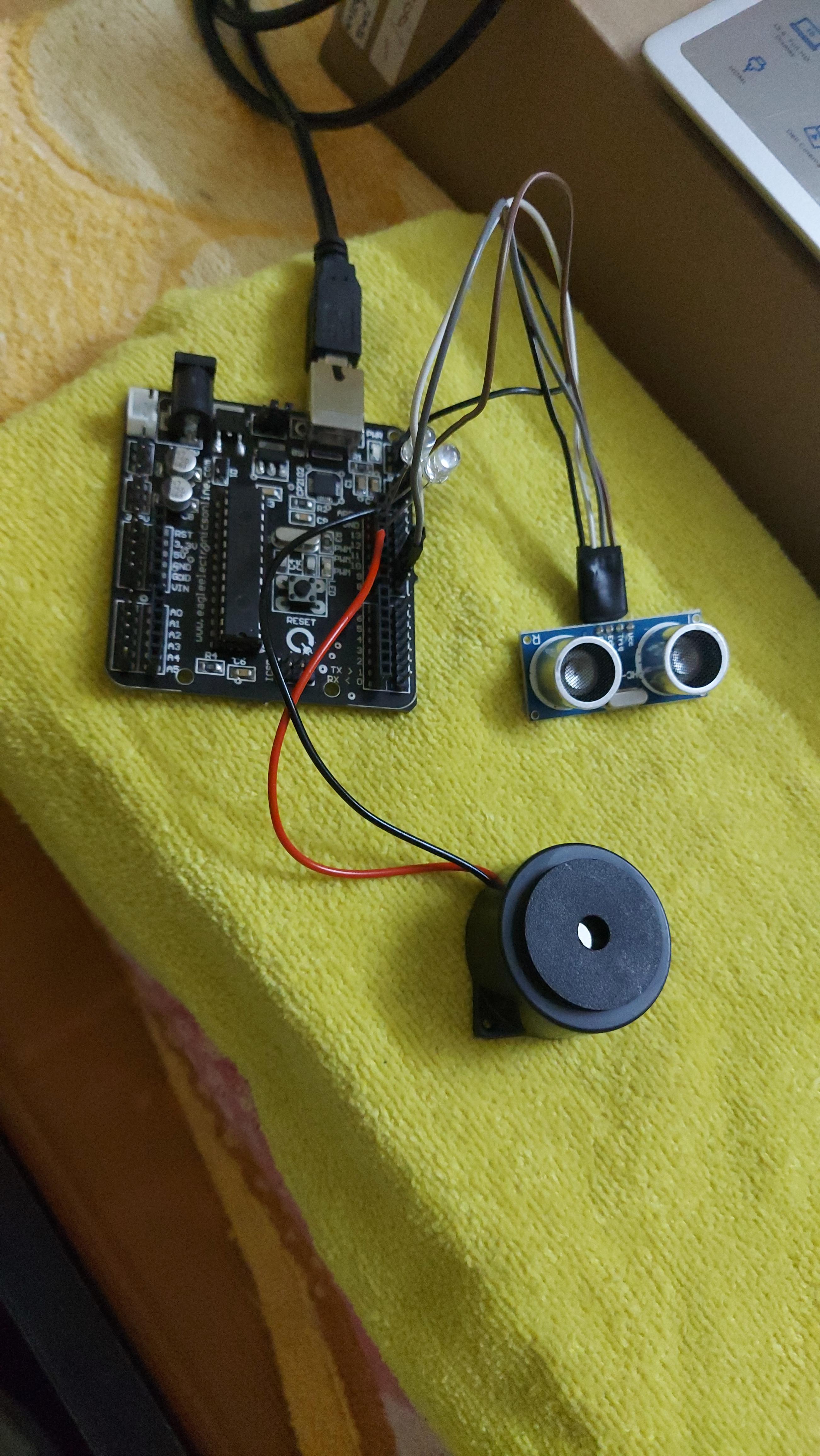
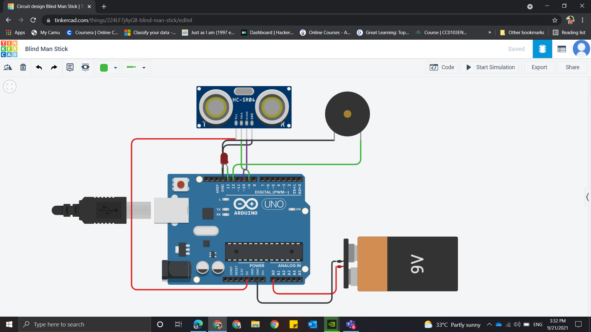
Connections with Arduino and Sensor
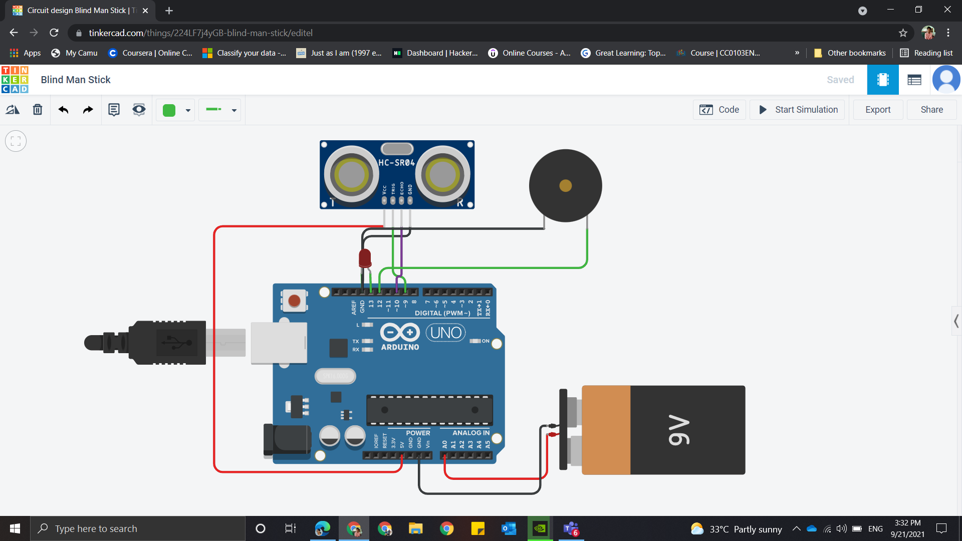
- Connect the Vcc of the Ultrasonic Sensor to the 5V power supply of the Arduino board.
- Connect the Trig pin of the Ultrasonic Sensor to the 9th digital input pin of the Arduino board.
- Connect the Echo pin of the Ultrasonic Sensor to the 10th digital input pin of the Arduino board.
- Connect the ground of the Ultrasonic Sensor to the Ground of the Arduino board.
Connections with other components:
- Connect the positive terminal of the DC buzzer to the 11th digital input pin and negative terminal to the ground of the Arduino board
- Connect the positive terminal of the battery to the Vin or to the analog pin and negative terminal to the ground of the Arduino board
Carefully connect the Jumper wires between the board and components.
Arduino Sketch
Let's upload the required code to the Arduino board
*The code is written for alerting the obstacle at a distance of 30cm
// defines pins numbers
const int trigPin = 9;
const int echoPin = 10;
const int buzzer = 11;
const int ledPin = 13;


// defines variables
long duration;
int distance;
int safetyDistance;


void setup() {
pinMode(trigPin, OUTPUT); // Sets the trigPin as an Output
pinMode(echoPin, INPUT); // Sets the echoPin as an Input
pinMode(buzzer, OUTPUT);
pinMode(ledPin, OUTPUT);
Serial.begin(9600); // Starts the serial communication
}


void loop() {
// Clears the trigPin
digitalWrite(trigPin, LOW);
delayMicroseconds(2);


// Sets the trigPin on HIGH state for 10 micro seconds
digitalWrite(trigPin, HIGH);
delayMicroseconds(10);
digitalWrite(trigPin, LOW);


// Reads the echoPin, returns the sound wave travel time in microseconds
duration = pulseIn(echoPin, HIGH);


// Calculating the distance
distance= duration*0.034/2;

// Safety Distance = 30 cm
safetyDistance = distance;
if (safetyDistance <= 30){
  digitalWrite(buzzer, HIGH);
  digitalWrite(ledPin, HIGH);
}
else{
  digitalWrite(buzzer, LOW);
  digitalWrite(ledPin, LOW);
}


// Prints the distance on the Serial Monitor
Serial.print("Distance: ");
Serial.println(distance);
}
Fixing the Components in the Walking Stick
.png)
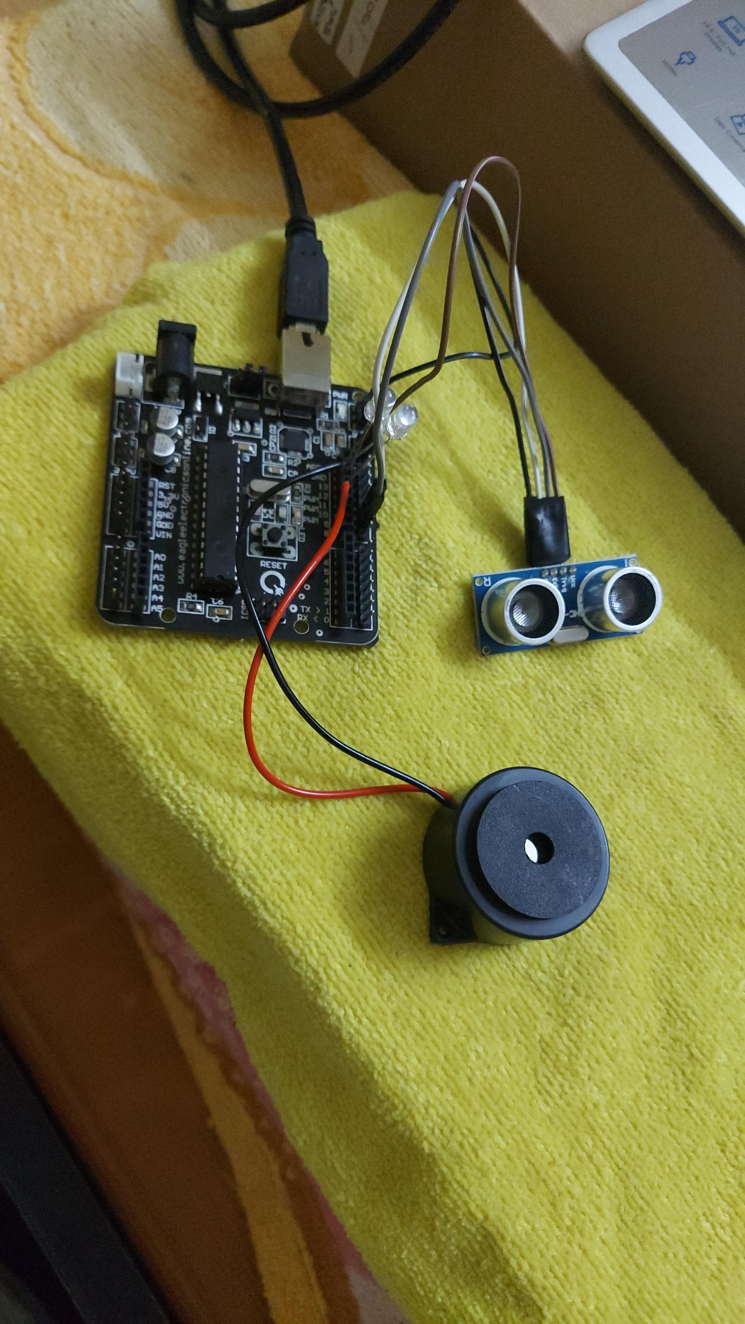
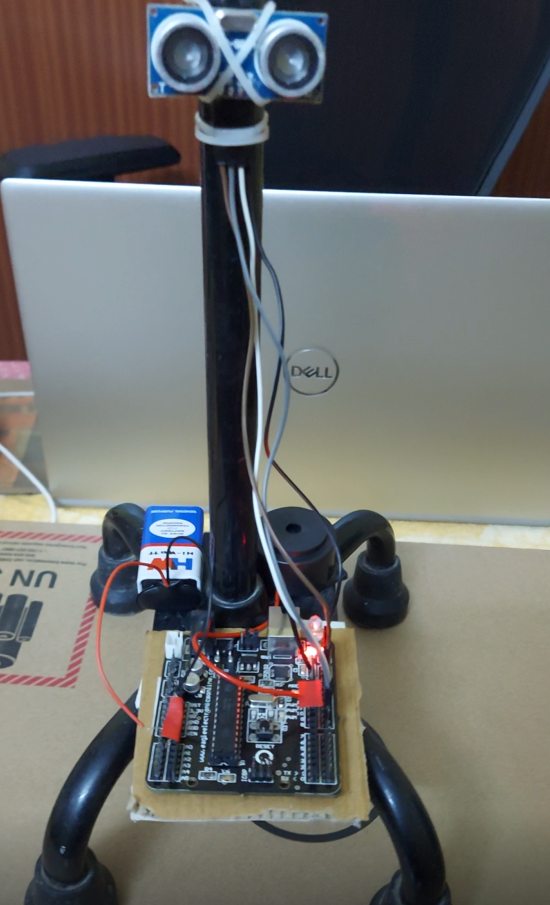
Now it's time to fix our circuit in the Stick
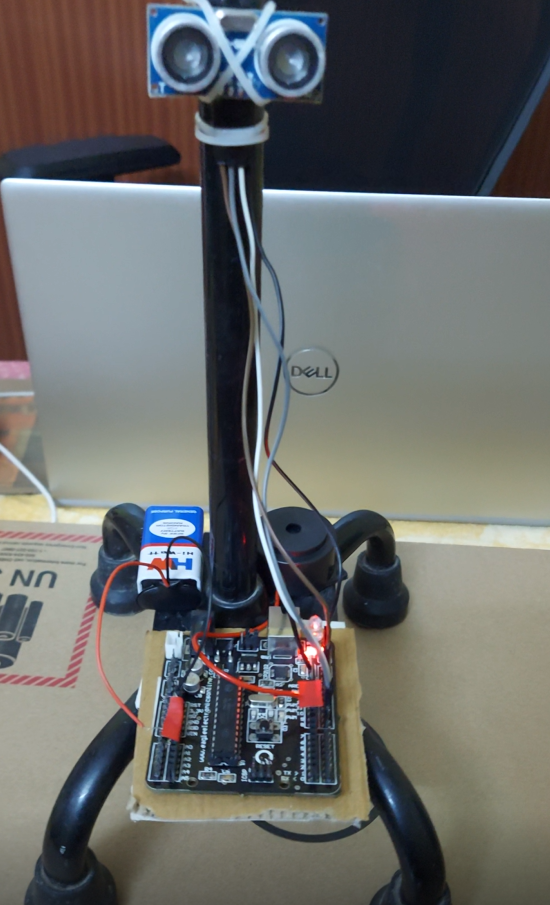
I have used an walking stick in this project. I fixed my board battery and Buzzer on the base of the stick and sensor placed slightly above it using double sided tape, glue and some cable tie clips for better fixation.
You could also use a PVC pipe. Cut the PVC pipe according to height requirements. Then fix the components using glue and tapes.
You can show your creativity to make the stick more attractive and sturdy.
Simulation Using Tinker Cad
.png)
.png)
Simulation:
You could also try this circuit in Tinker CAD :)
Make the connections as said above and upload the code.
Start Simulating!
Outcome
Hope You loved it!
Thanks for Reading my instructable.
All the Best for your DIY
Happy Doing :) 😀