DIY Smart Home Control Panel With AiPi-Eyes-R2
by tech_nickk in Circuits > Gadgets
9057 Views, 121 Favorites, 0 Comments
DIY Smart Home Control Panel With AiPi-Eyes-R2


Building a Unified Smart Home Control Panel with AiPi-Eyes-R2
The smart home era is here to stay, but the way we interact with our connected devices is still far from perfect. We often find ourselves fumbling with multiple apps and complex interfaces, which can be frustrating and counterintuitive. This project aims to solve that problem by creating a dedicated, unified control panel for your home using the AiPi-Eyes-R2 development module from Ai-Thinker. This custom solution allows you to centralize control, simplify your daily routines, and create an elegant, always-on interface that truly unifies your smart home experience.
The Practicality of a Dedicated Panel
While smartphone apps are a great way to manage smart devices, they often create a fragmented and frustrating user experience. A dedicated control panel solves these common pain points by offering a centralized and intuitive hub for your entire household.
- A Unified Dashboard: The biggest advantage is a single, custom dashboard for all your connected devices. Instead of juggling separate apps for your Philips Hue lights, Nest thermostat, and smart plugs, you can build a single interface that displays and controls everything from one screen. This simplifies daily tasks and makes your smart home feel truly integrated.
- Always Ready, Always Available: Unlike a phone that can be misplaced, have a dead battery, or require an unlock code, a dedicated panel is always on and always accessible. It's the go-to place for anyone in the family—even guests—to perform common actions without needing a phone or technical know-how.
- Enhanced Reliability and Security: Many smart panels process commands locally, meaning they can continue to function even if your internet connection goes down. This is crucial for essential functions like security alerts or emergency lighting. Furthermore, the panel can be a dedicated screen for displaying live feeds from your security cameras, giving you constant peace of mind without tying up your phone.
- Beyond Control: A Central Family Hub: This panel can be so much more than a collection of buttons. With the AiPi-Eyes-R2's screen, you can create a family communication center that displays a shared calendar, real-time weather updates, digital photo albums, or a custom-built digital noticeboard for messages.
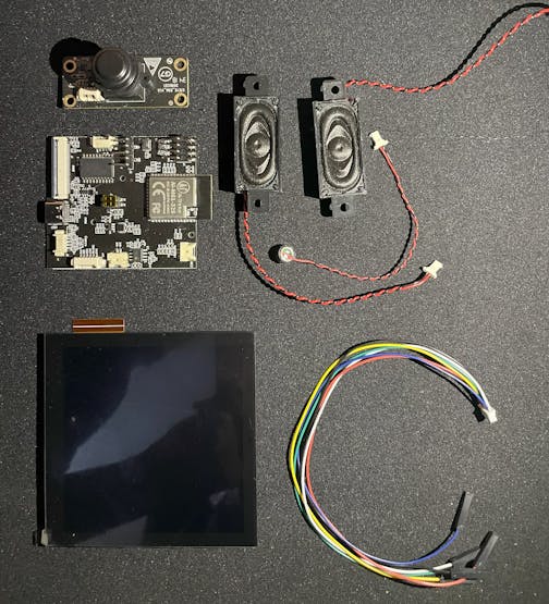
Supplies
- AiPi-Eyes-R2 Module
- FTDI Module
- Jumper Wires
Introducing the AiPi-Eyes-R2 Board: the Brains of the Operation
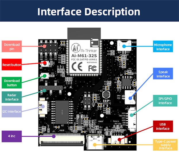
The AiPi-Eyes-R2, a feature-rich board from Ai-Thinker, is the perfect choice for this project. It is based on the Ai-M61-32S module, a powerhouse with a RISC-V 32-bit CPU, Wi-Fi 6, and BLE 5.3 connectivity.
Key features that make it ideal for a smart home panel:
- Display: A vibrant 4-inch, 480x480 pixel capacitive touch screen provides a large, responsive interface for your custom UI.
- Connectivity: Wi-Fi 6 and BLE 5.3 ensure robust and reliable communication with all your smart devices.
- Audio: The integrated microphone and speaker open the door to voice control capabilities and audio notifications for security alerts or calendar reminders.
- Camera: A DVP camera interface allows for advanced vision-based applications, such as a security camera feed or even facial recognition for user authentication.
- Peripherals: A rich set of interfaces (I²C, SPI, UART, etc.) for connecting to a wide array of sensors and other devices, expanding the panel's functionality.
For the first version I will not use all the features but we will add them gradually.
Getting Started: the Learning Curve
This project is best suited for makers with some prior experience in electronics and embedded systems. You'll be working with a command-line interface, compiling a custom SDK, and flashing firmware. While there is a learning curve, the open-source nature of the project and its active community provide a wealth of documentation and support.
Software Setup: Installing the SDK and Repository
To begin, you will need to set up your development environment. This guide assumes you are using a Linux-like environment, such as a Linux distribution or a tool like WSL on Windows.
- Clone the Ai-Thinker Repository: Open your terminal and clone the main project repository.
- Initialize Submodules: The SDK and other necessary components are included as submodules. Navigate into the cloned directory and initialize them.
- Setup the SDK: The SDK needs to be configured. The following steps assume you're in the AiPi-Open-Kits directory.
Note: The exact scripts and paths may vary slightly. Refer to the official Ai-Thinker documentation for the most up-to-date instructions.
Here is the link to the Official Documentation
Burning the Firmware
For this project, we will use the provided demo firmware to get our control panel up and running quickly. This demonstrates the board's capabilities and gives you a solid foundation for your own customizations.
While the SDK provides a command-line method (make flash), an alternative for beginners or those who prefer a GUI is the Bouffalo Lab burning tool.
- Download the Burning Tool: Download the tool Here
- Connect the Board: Use a USB to TTL(Serial) Adapter like the FTDI one to connect the AiPi-Eyes-R2 to your computer.
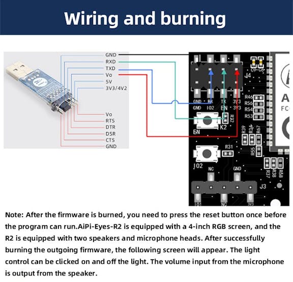
- Enter Programming Mode: The burning process requires the board to be in a specific programming mode.
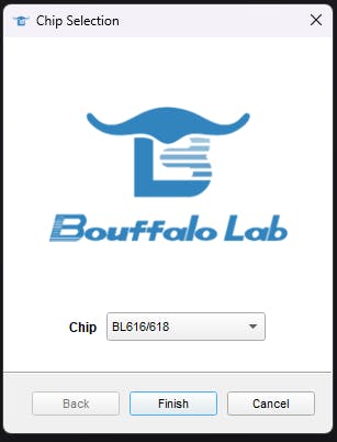
- Open BLDevCube.exe, select BL616/618, and click Finish.
- On the AiPi-Eyes-R2 board, press and hold the "Download" button (S2).
- While holding the "Download" button, press the "Reset" button (S1) and then release it.
- Now, release the "Download" button. The board should now be in programming mode, and the burning tool will be able to detect it.
- Flash the Firmware: In the burning tool, select the demo firmware file (.bin) and start the flashing process.
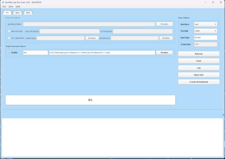
- Download the Demo code Here: AiPi-Eyes-R2 Demo Firmware
- If you face challenges while burning the firmware try to adjust the baud rate to the maximum speed your USB to SERIAL converter supports
- Reset and Run: Once the burning is complete, press the "Reset" button on the board. The new firmware should now be running, and you will see the demo interface on the screen.
Compiling and Running a Simple Example
To move beyond the pre-compiled demo and start developing your own applications, you'll need to compile the code yourself. Let's use a simple "hello world" style example to get familiar with the process.
- Navigate to an Example: The SDK includes several examples. Let's choose the helloworld example located in the examples directory.
- Configure the Board: You need to tell the build system which board you are targeting. This command sets up the AiPi-Eyes-R2 as the target.
- Compile the Code: Run the make command to compile the source code into a binary file.
This will generate a .bin file in the project's build directory. You should see a successful compilation message in your terminal.
- Flash the Compiled Firmware: Now, use the command-line make flash to burn your newly compiled binary to the board. The board must be in programming mode (as described in section 5) for this to work.
- Reset and Verify: After the flashing process is complete, press the "Reset" button on the AiPi-Eyes-R2. The helloworld example will now be running on your board. You can use a serial monitor (like PuTTY or minicom) to connect to the board's UART and see the "Hello World" message being printed.
The Final Touches: Casing and Assembly
Transforming the raw circuit board into a finished product requires a custom enclosure. For this project, a 3D-printed case provides a clean, professional look and protects the electronics.
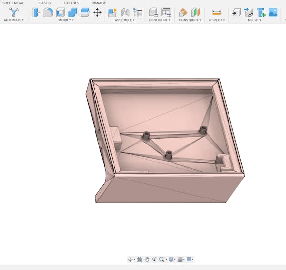
Designing the Case (Fusion 360)
The design process will leverage the existing case design provided by Ai-Thinker. We'll use Fusion 360 to inspect, and modify this design before printing.
- Obtain the Provided Model: Download the 3D model file here AiPi-Eyes-R2 enclosure.
- Inspect and Modify the Model: Open the downloaded model in Fusion 360. Take this opportunity to inspect the design, ensuring all components fit together and that cutouts for ports and buttons are correctly sized. You can make minor adjustments, such as adding a logo, changing the thickness of walls, or adjusting screw hole tolerances if needed.
- Export for Printing: Once you are satisfied with the design, export the two case parts (front and back) as separate STL files.
1 / 2
3D Printing and Finishing
The 3D printing process will turn your digital design into a physical object.
- Printing: Print the case using a filament like PLA or PETG. To get the best surface finish, you may need to experiment with different print orientations and support settings. For example, printing with the front face up can lead to a smoother finish.
- Post-Processing: After printing, you may need to do some post-processing to get a perfect finish.
- Sanding: Lightly sand the outer surfaces to smooth out any layer lines.
- Tapping Screw Holes: The screw holes may be a tight fit. Use an M2 screw to pre-thread the holes about 1mm deep to make final assembly easier.
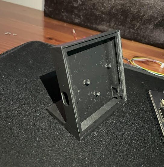
Assembly
With the parts printed and finished, it's time to put everything together.
- Mount the PCB: Carefully screw the AiPi-Eyes-R2 PCB into the bottom part of the case, ensuring the ports and screw holes align.
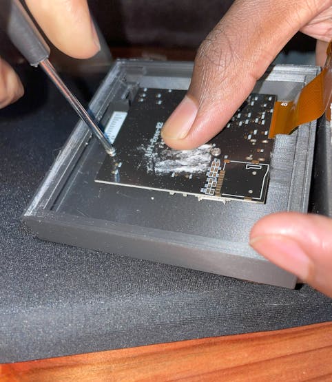
- Attach the Screen: Connect the screen to the PCB using its ribbon cable. The casing holds the screen secure to the case and prevent it from shifting.
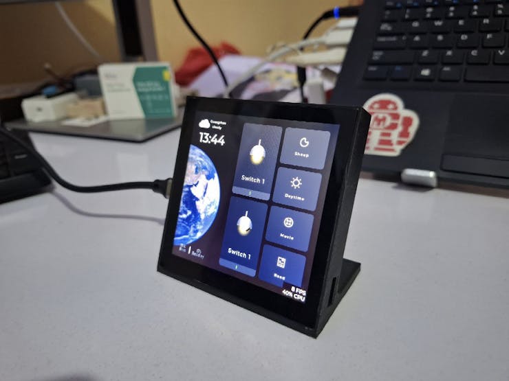
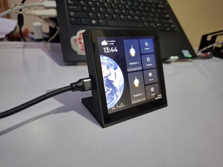
Results
The end result is a sleek, functional, and fully enclosed smart home control panel. The interface is simple to interact with as it is touchscreen.
Doesn't it look good??
Demo Video
Work in Progress
This project is still a work in progress.Future improvements will include:
- Adding integration with more smart devices.
- Custom UI themes for better readability.
- Optional voice control integration.
- Battery backup for portable use.
The beauty of this approach is that it evolves with your smart home — you’re not locked into any manufacturer’s ecosystem or design decisions.
If you have reached this Pont it means you have learnt something new and you probably enjoyed it. Don't forget to leave a like and comment your thought or what you think I should make next : )