DIY SMART LED MATRIX (ESP8266 + WS2812 / NeoPixels )
by mcmchris in Circuits > LEDs
9261 Views, 18 Favorites, 0 Comments
DIY SMART LED MATRIX (ESP8266 + WS2812 / NeoPixels )
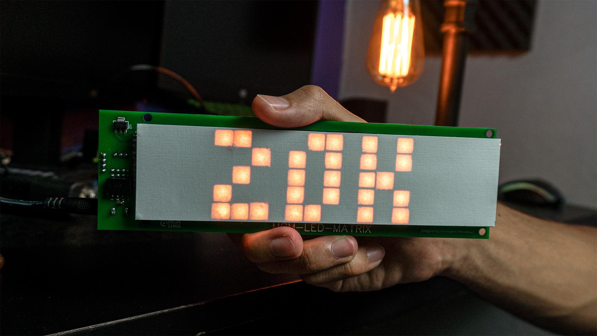
Here is my introduction to a project that I am very excited to show you. It's about a DIY Smart LED Matrix that will let you show on it, data, such as YouTube Stats, your Smart Home Stats, as temperature, humidity, can be a simple clock, or just show text and animations.
In this first tutorial I will be making it first test and text showing.
If you are a visual learner I know that a video worth more than 1000 words, so here is a Tutorial video. (I am a Spanish speaker, so please consider turning on English subtitles):
Hope you to enjoy the project!.
Skills Needed.
.png)
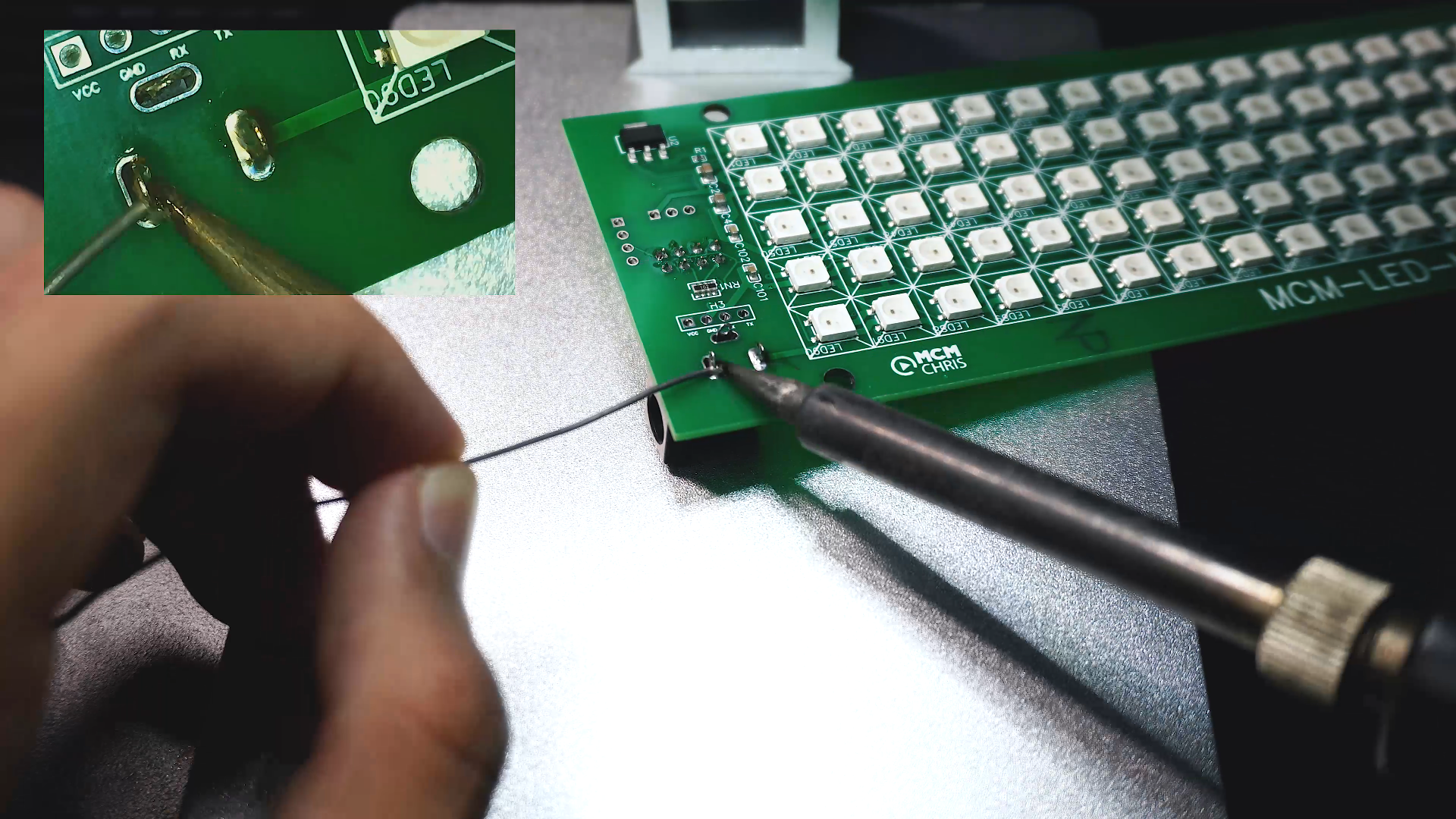
As you can noticed, nothing looks very difficult on this project, but you will need some basics knowings about:
-Using the Arduino IDE.
-3D printing or Handcraft (for the Grid).
-Welding.
-Wiring.
Components and Parts List
.png)
.png)
A good place I can recommend to find your components, it's MakerFocus, it's an Open Source Hardware Store!
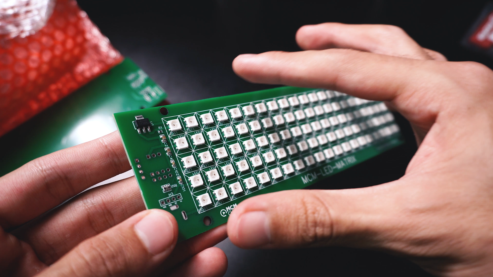
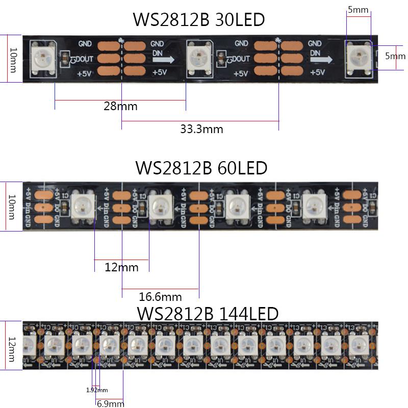
- PCB, you can choose between the No LEDs version and ADD the LED's Strips by yourself, or the one with the LED's.
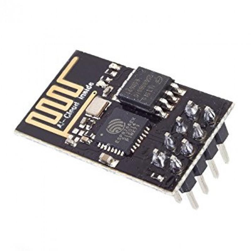
- ESP8266 (Microcontroller).
- WS2812 LEDs Strips.
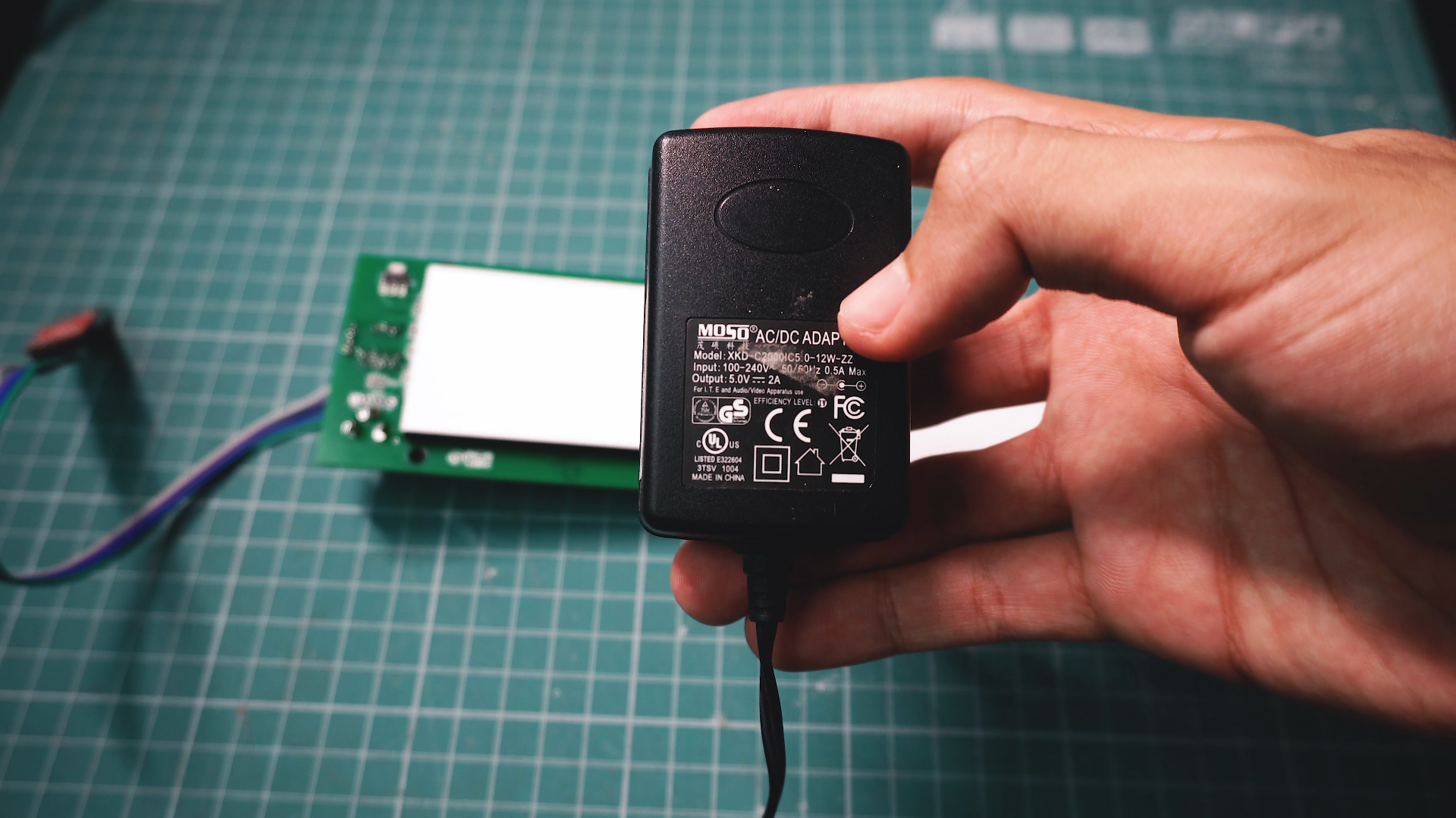
- 5v 2A Power Supply.
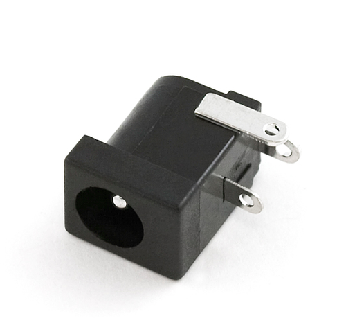
- PCB Power Jack.
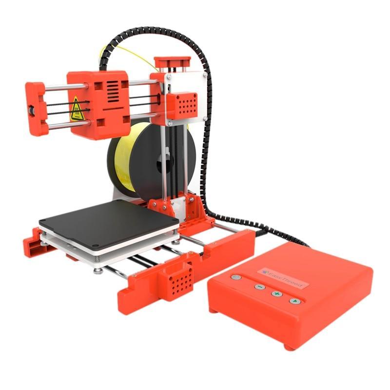
- 3D Printer (Optional) You can do the parts with cardboard or something rigid.
Circuit Diagram
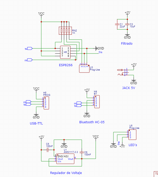


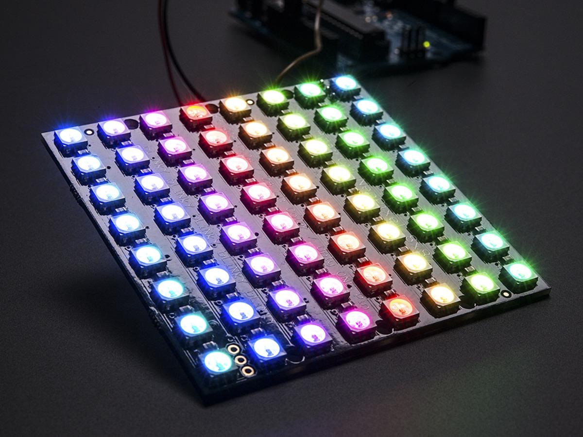
Here is the Circuit diagram, you have several options to make the project. You can just create the control part of the circuit, the one shown in the first image, then attach individual LEDs Strips as shown on the 3rd image.
Yo can also, instead of LED strips, use LED Panels.
It has all the internal conections of the circuit that will allow us to create the PCB design later.
I also attached the PDF of the Schematics so you can see it better.
PCB Design and Ordering
.png)
.png)
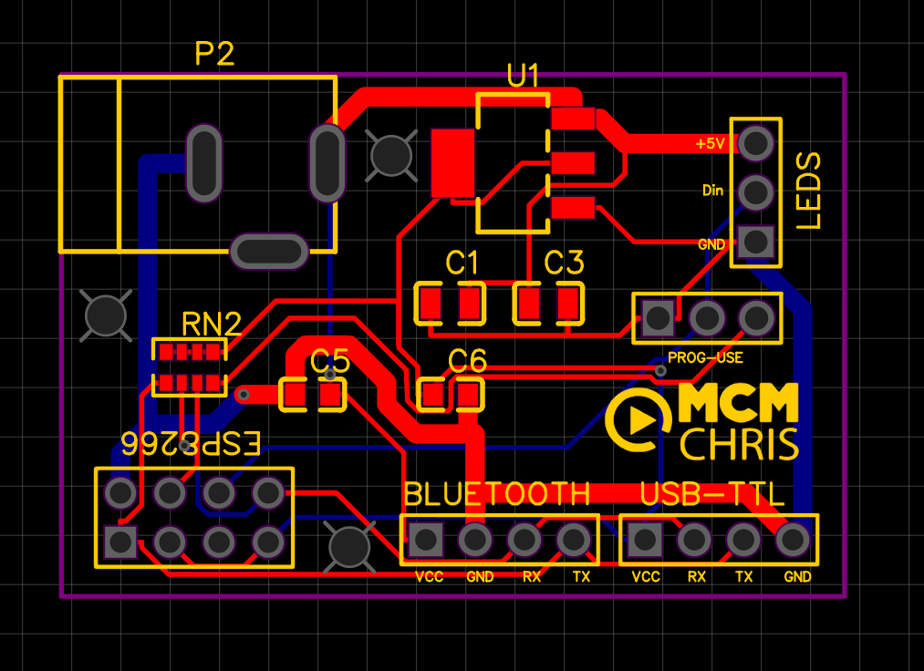
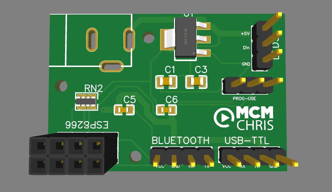
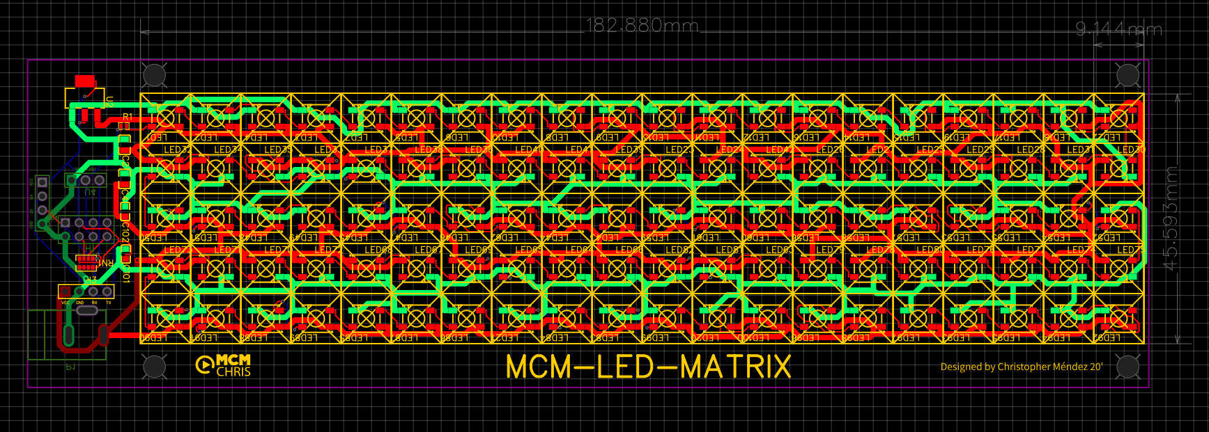
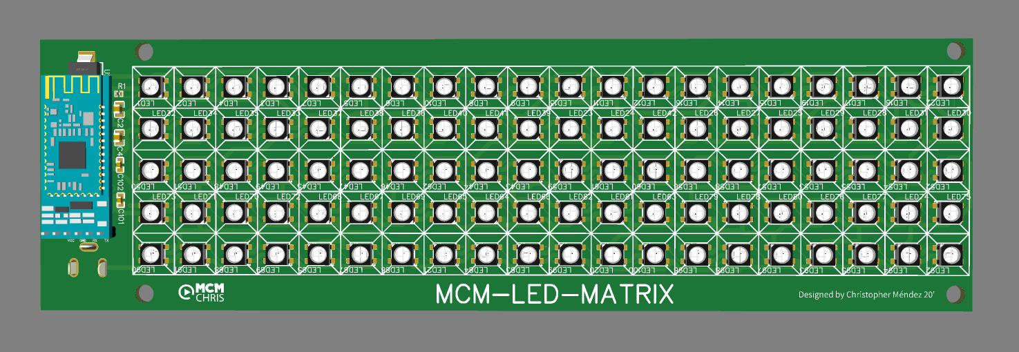
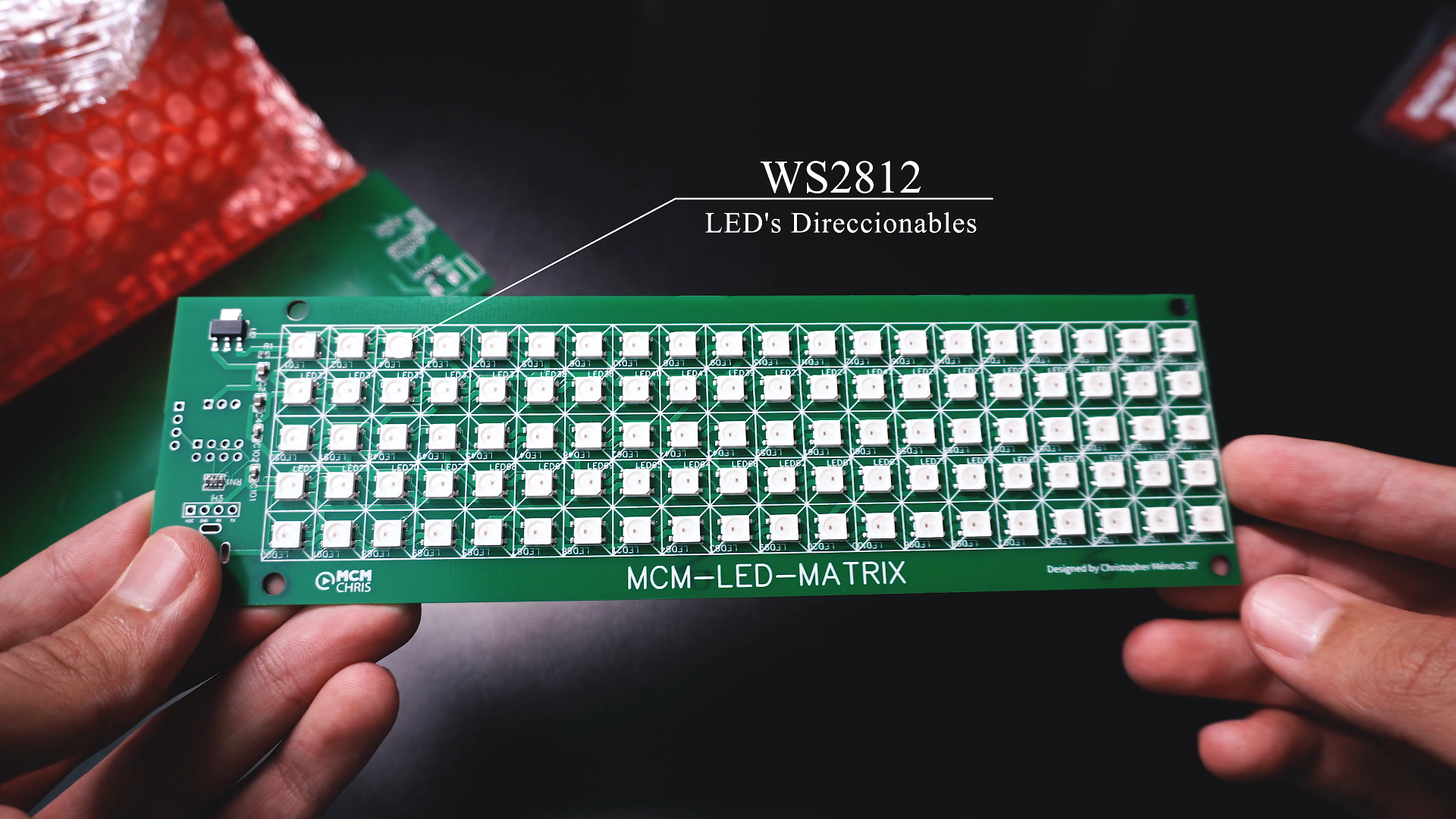
For the implementation of a good project we need a reliable assembly for the circuit that makes it up, and there is no better way to do it than with a good PCB.
Here you can download the Gerber, BOM and Pick & Place Files, the ones you need to order your PCB on your PCB manufacturing company.
I suggest JLCPCB:
Assembly
.png)
.png)
.png)
.png)
.png)
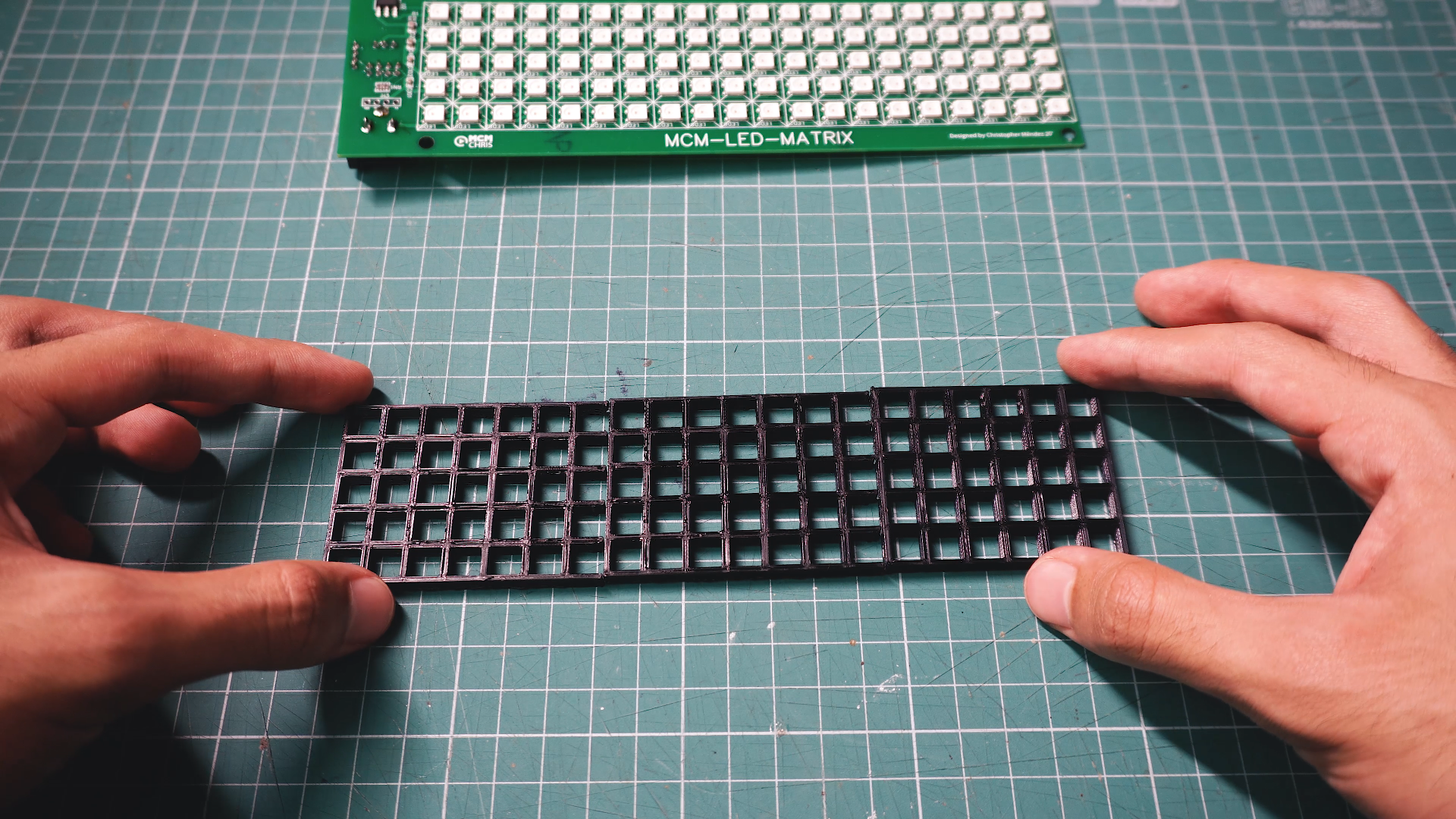
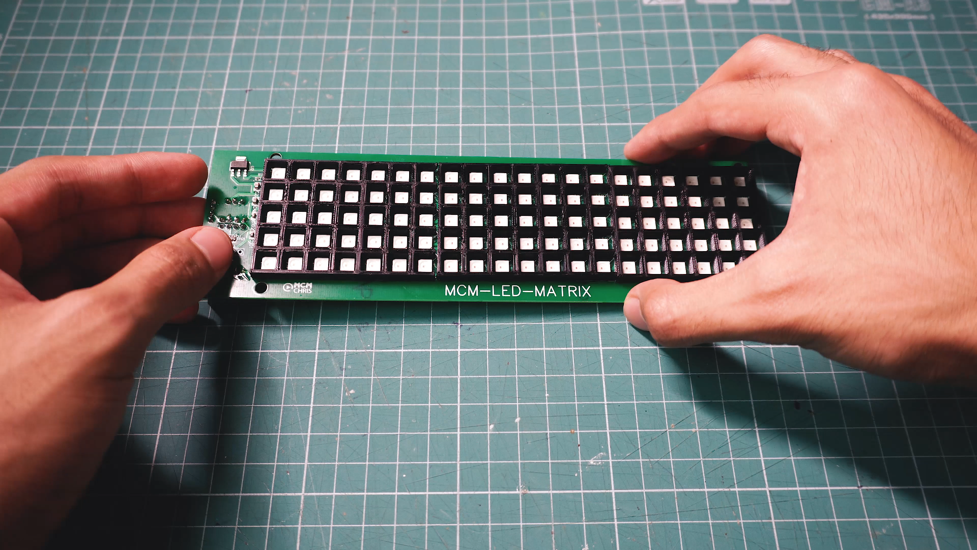
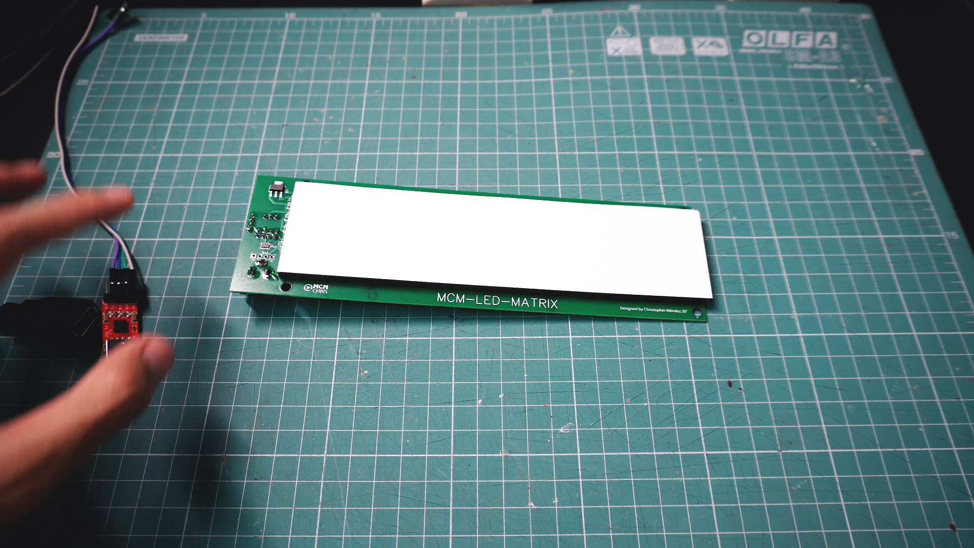
Print the Grid.
I printed the grid on different parts because of my tiny 3D printer.
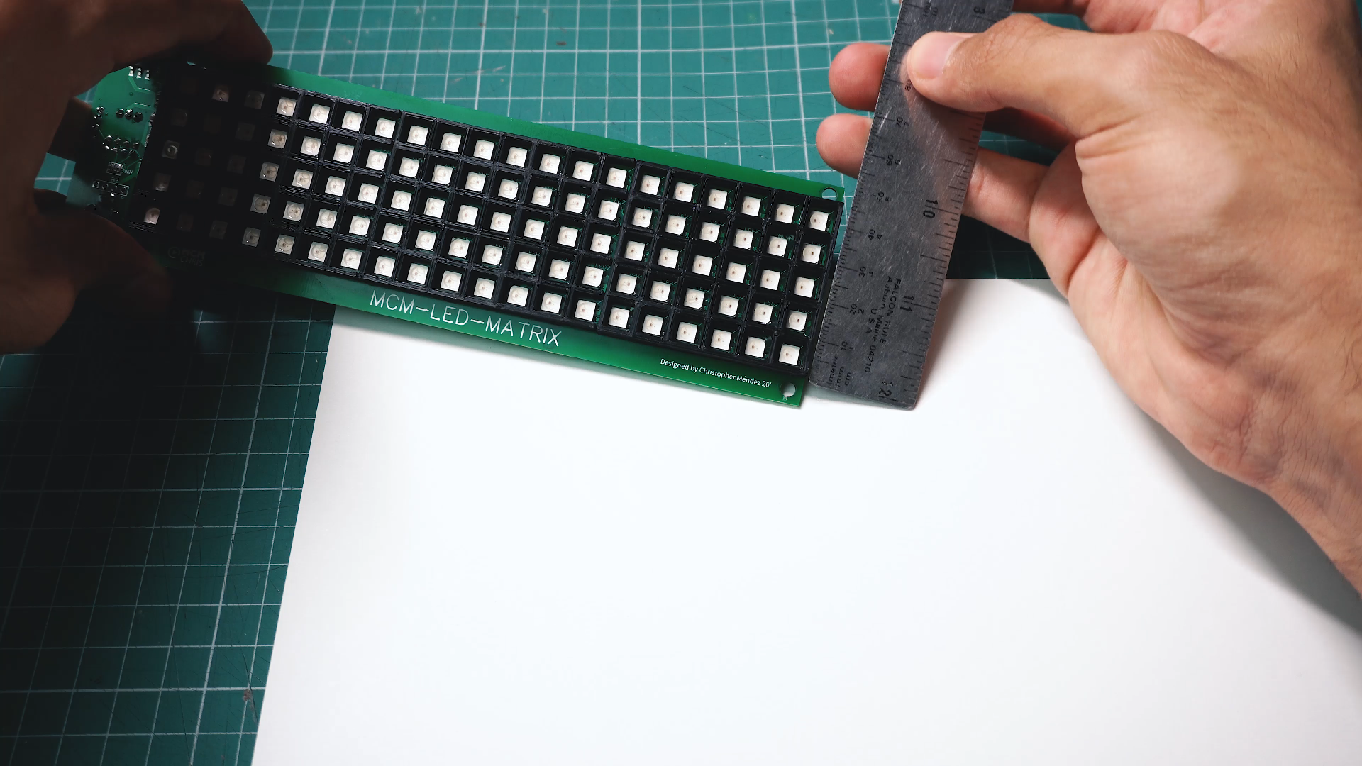
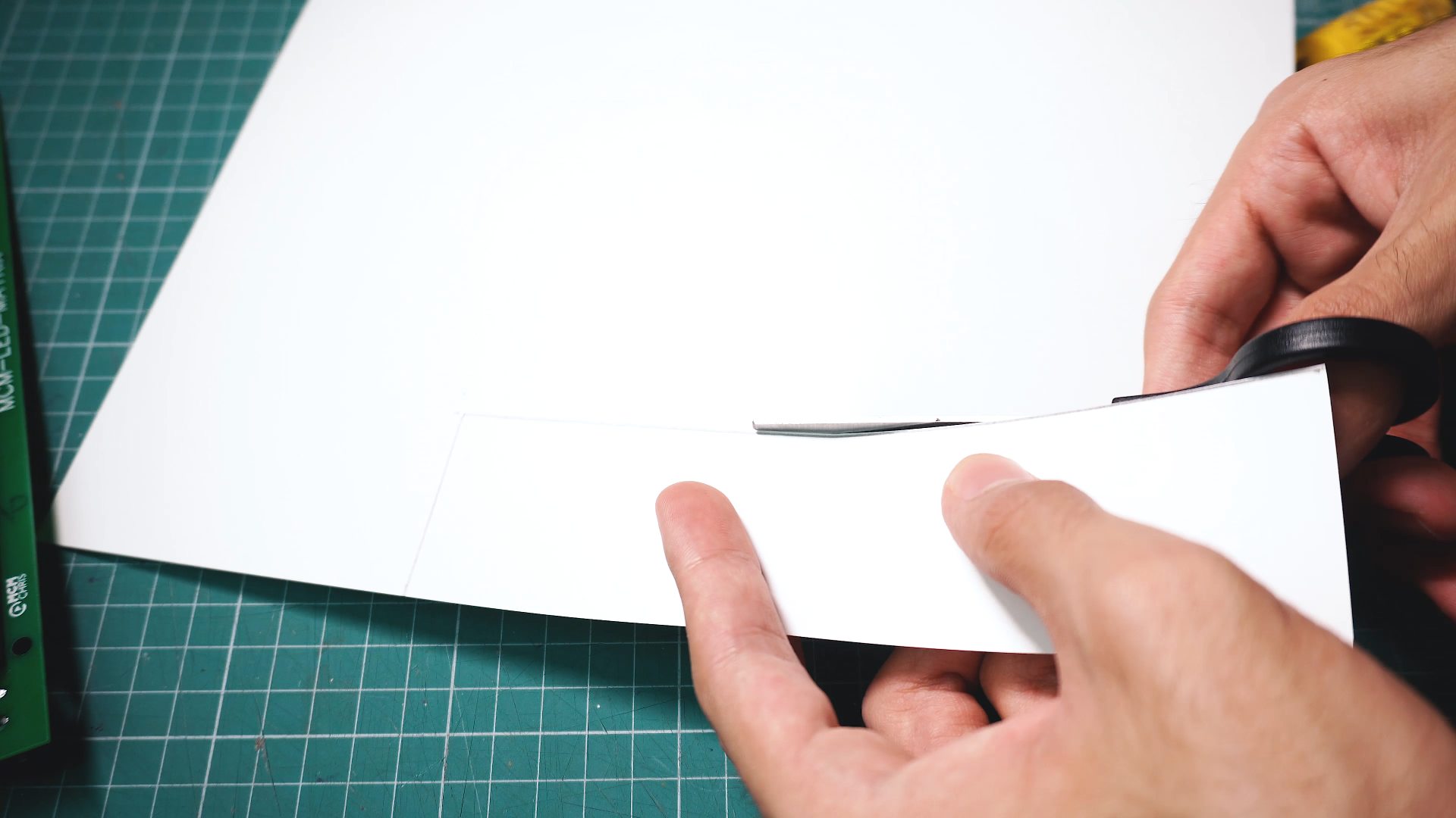
I cutted a piece of a rigid white paper to get a better pixel definition.
Attached the Grid Files. (You can design your own Grid).
I printed 2 Grid and 1 Grid2 pieces.
Programming the ESP8266 and Testing
.png)
.png)
.png)
.png)
.png)
.png)
.png)
.png)
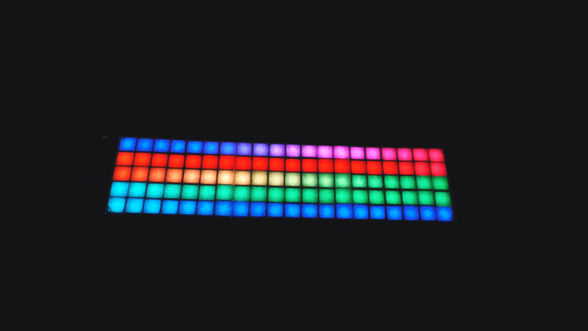
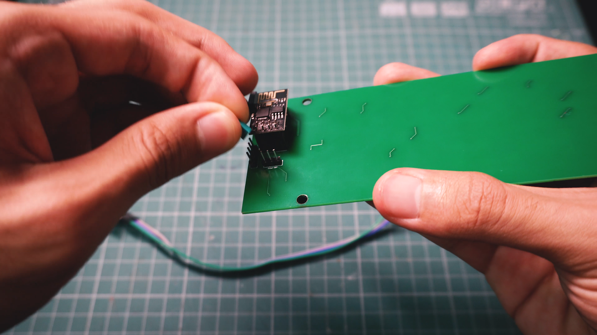
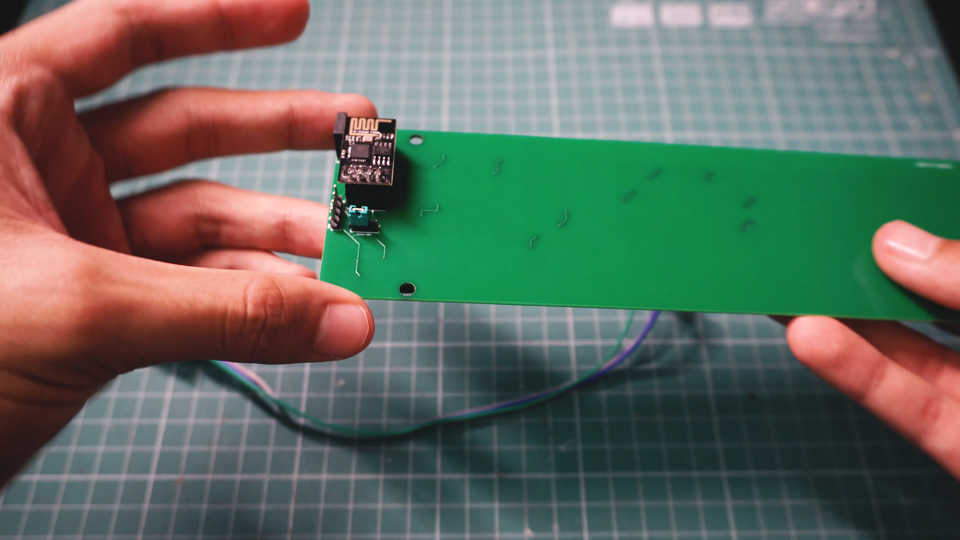
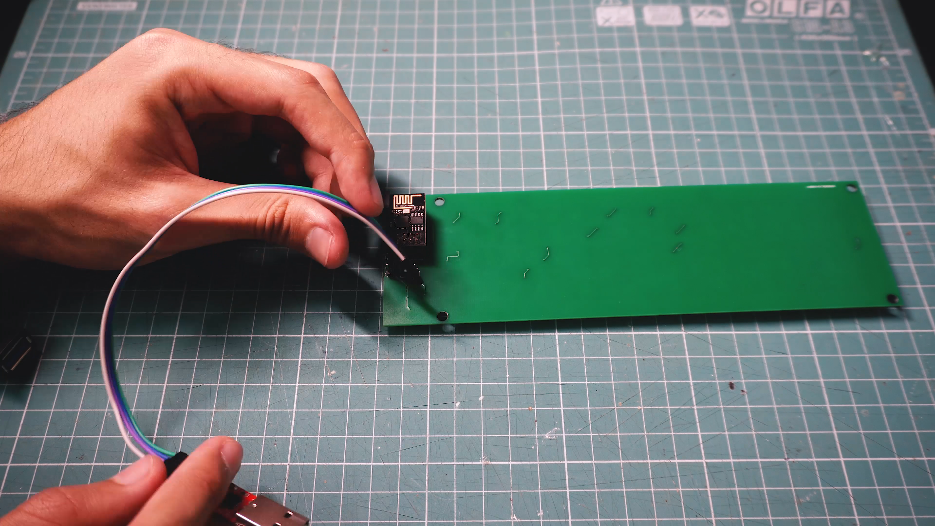
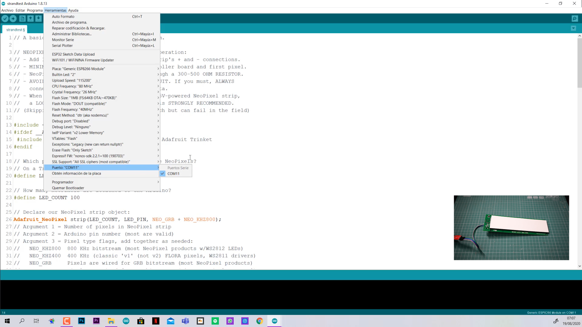
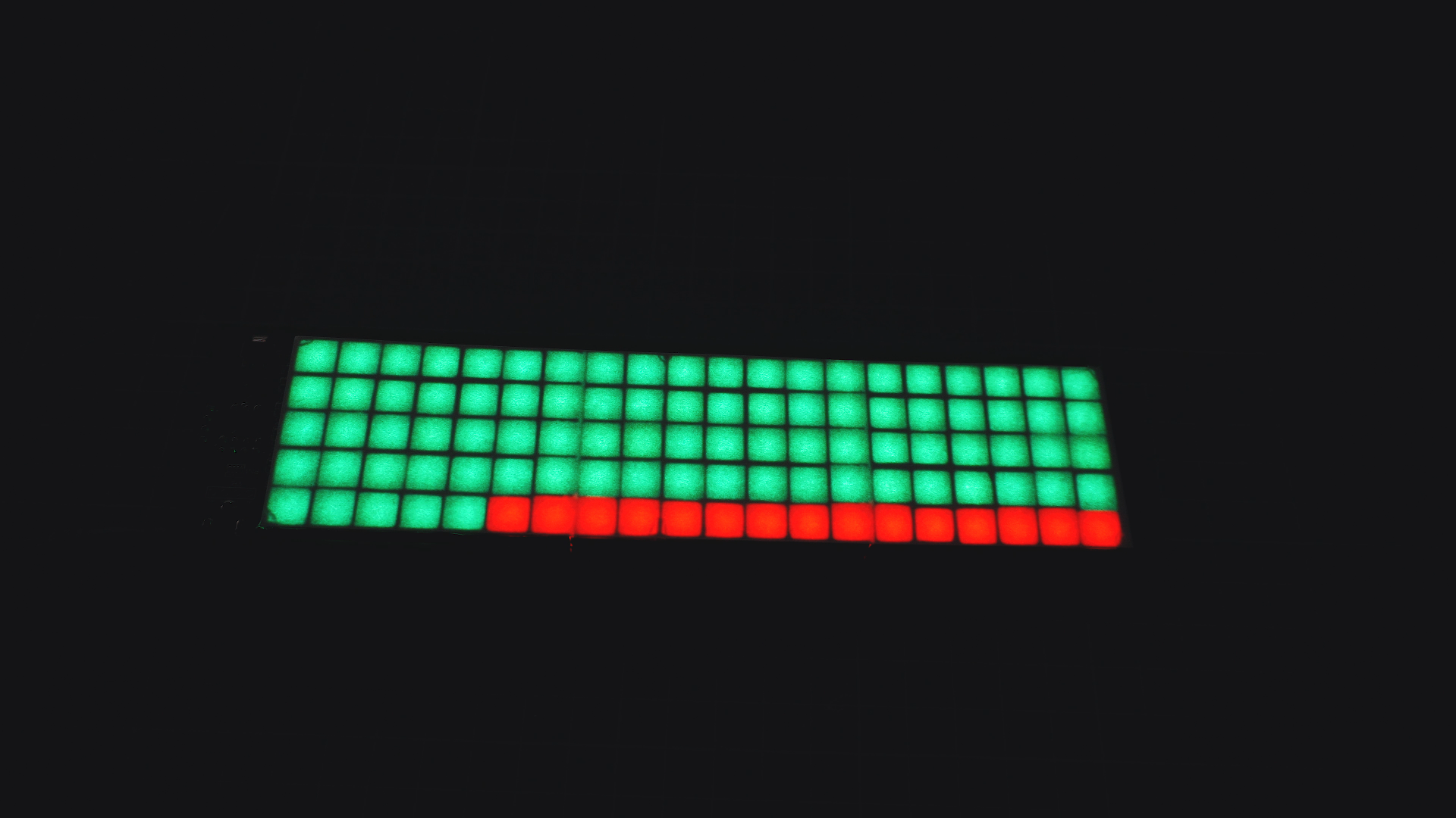
1- To program the ESP8266 we need to place the jumper on (PROG position), connect the USB to TTL converter to our PCB on it respectives pins and then to our PC, install the libraries and then upload. (Need to have the ESP8266 Packaje installed on your IDE).
2- Install the Libraries and Dependencies.
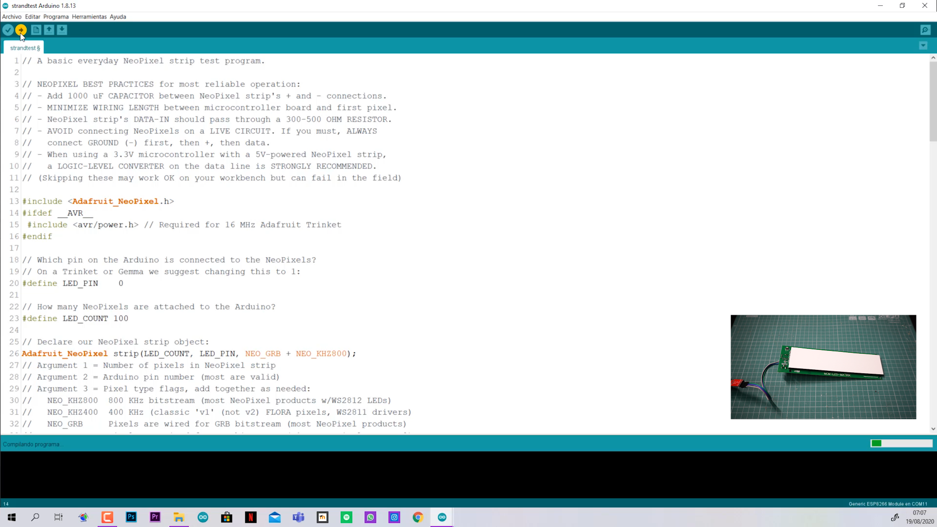
3- Restart the IDE, go to Archive > Examples > Adafruit NeoPixel > Strandtest.
-Edit the number of LEDs connected.
-Edit the Pin to "0" .(Where LEDs are connected).
4- Upload the sketch.
5- Jumper on USE, disconnect USB and connect the 5v power Supply.
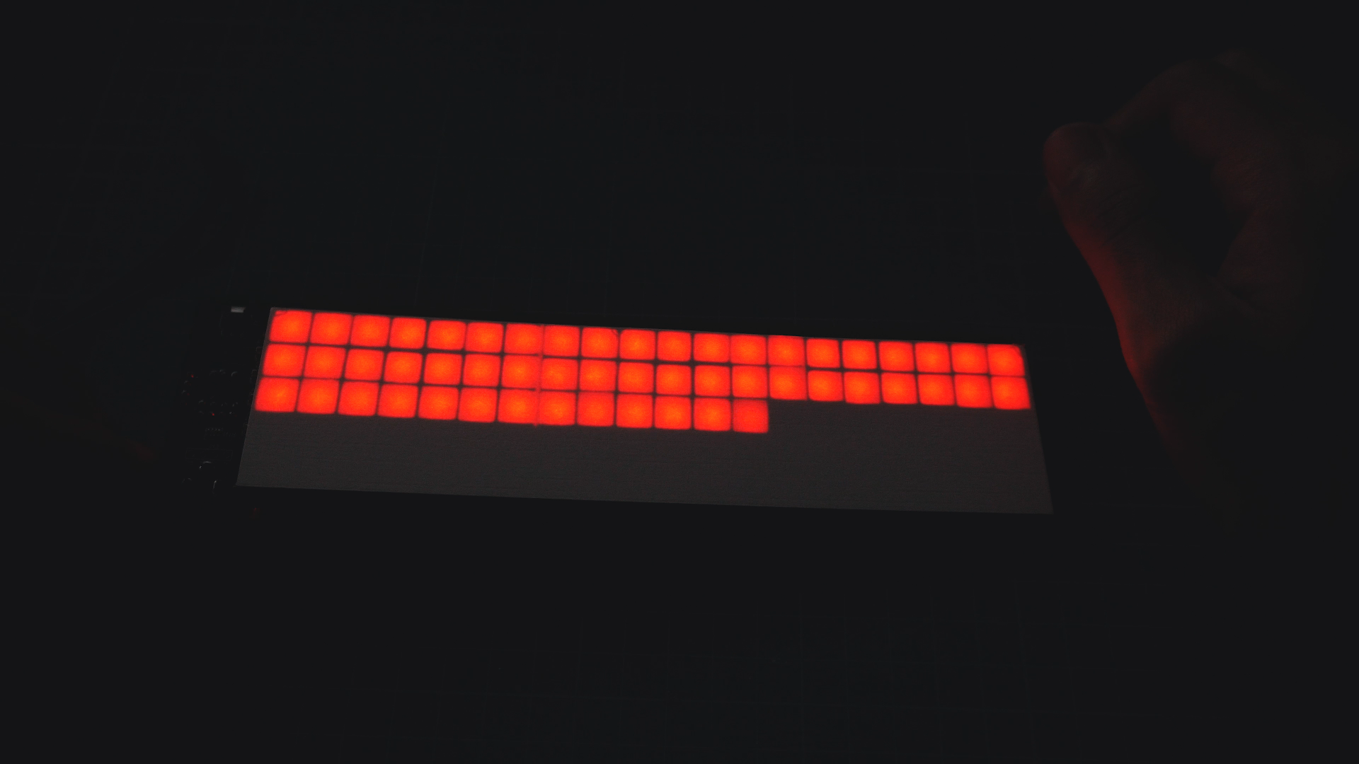
6- Verify that all your LEDs works fine.
NOTE: Use the 3.3v of the USB-TTL convertor to power the ESP. (Will burn with 5v).
Final Programming and Text Showing.
.png)
.png)
.png)
.png)
.png)
.png)
.png)
.png)
.png)
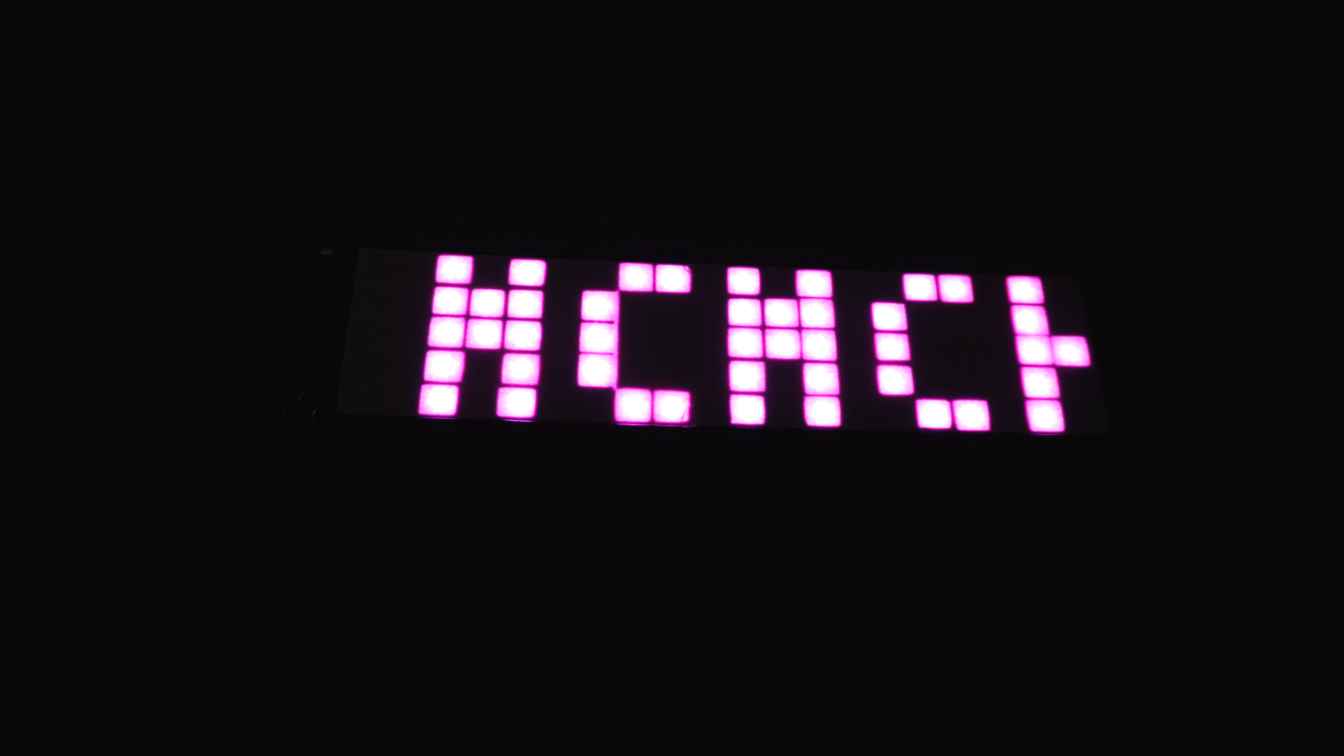
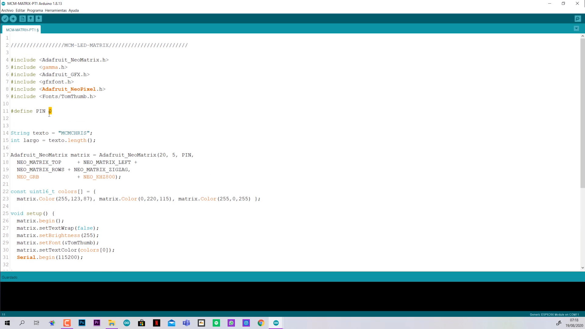
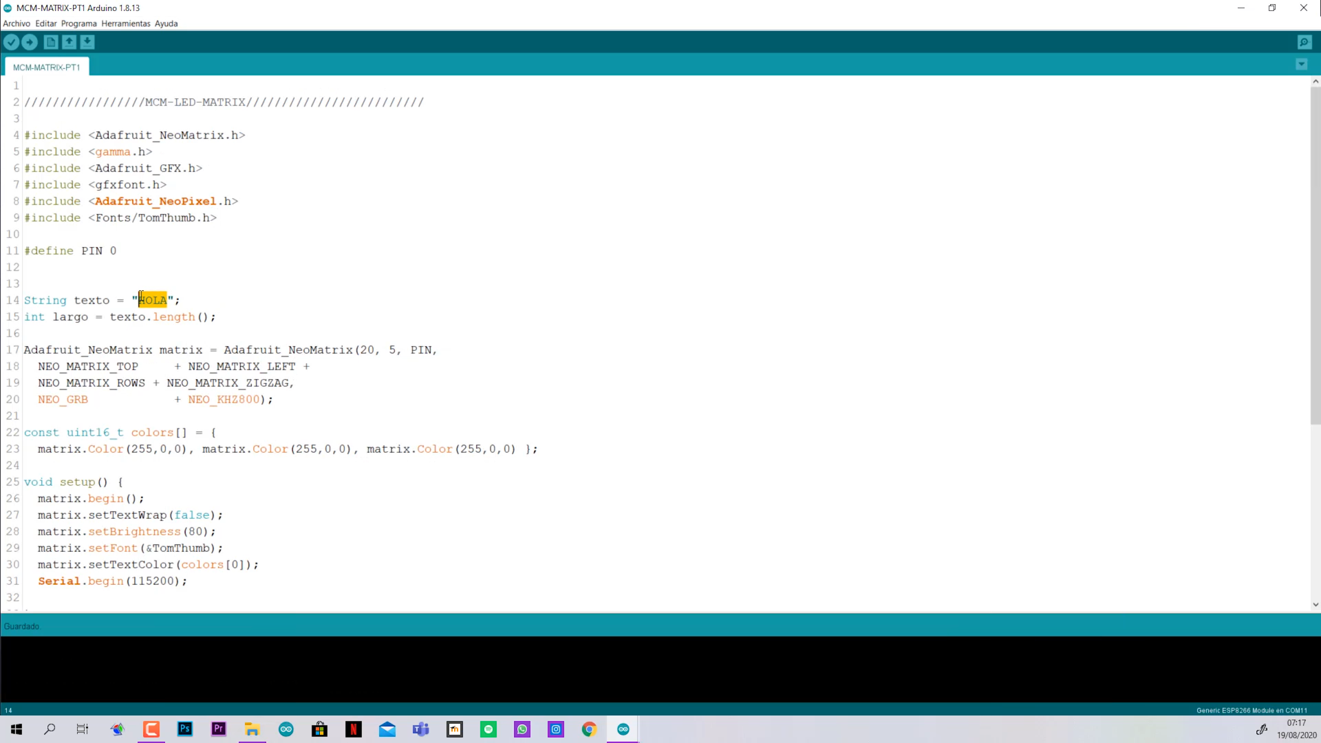
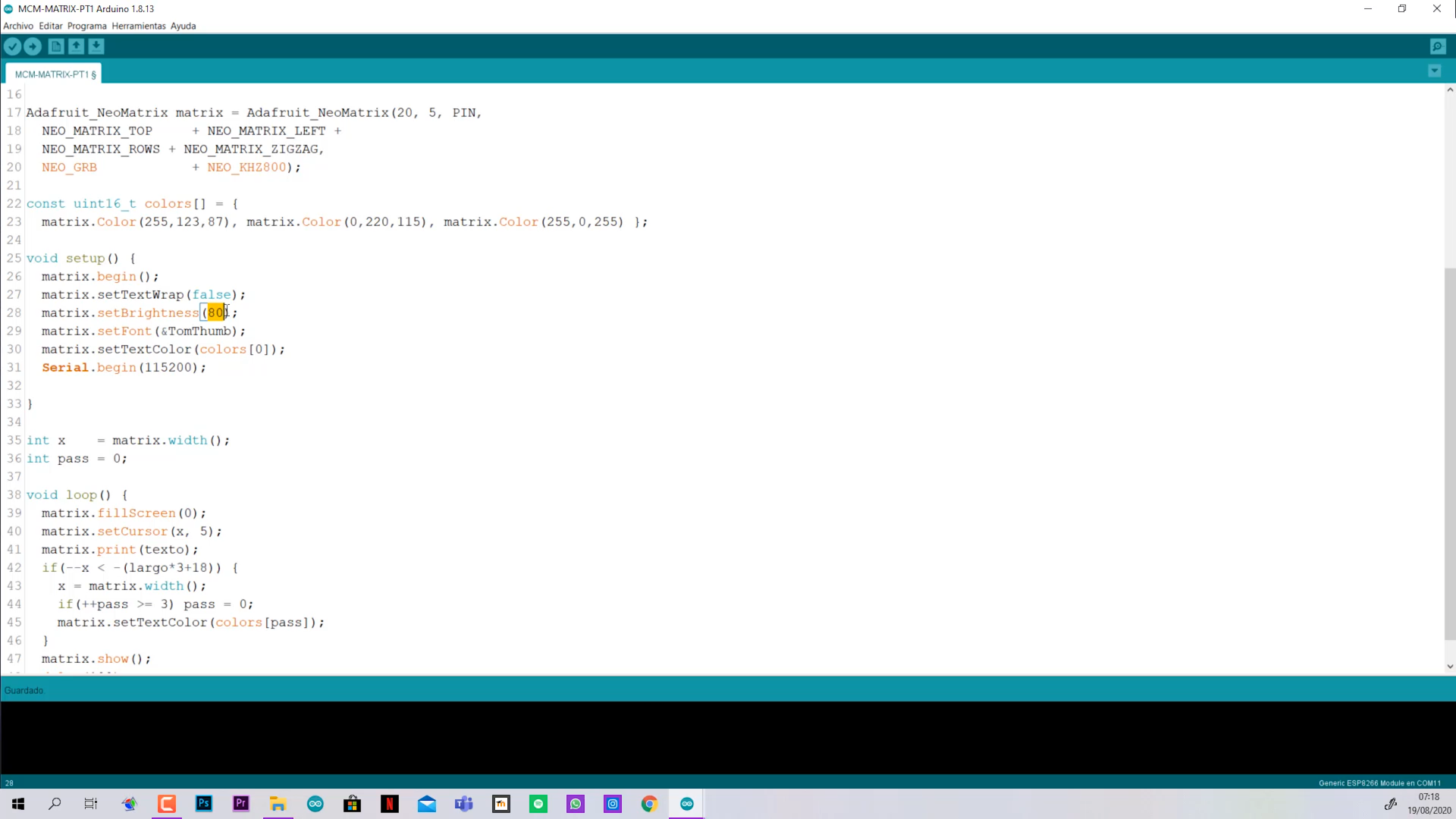
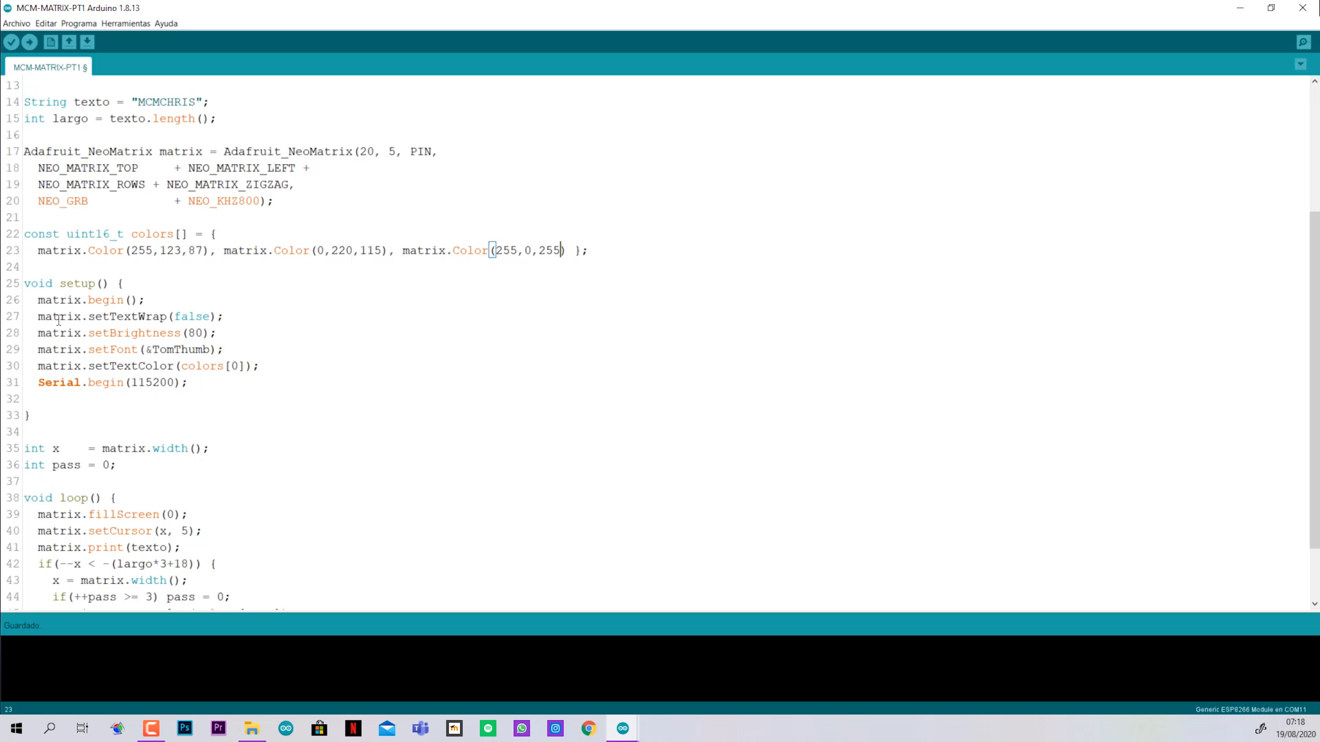
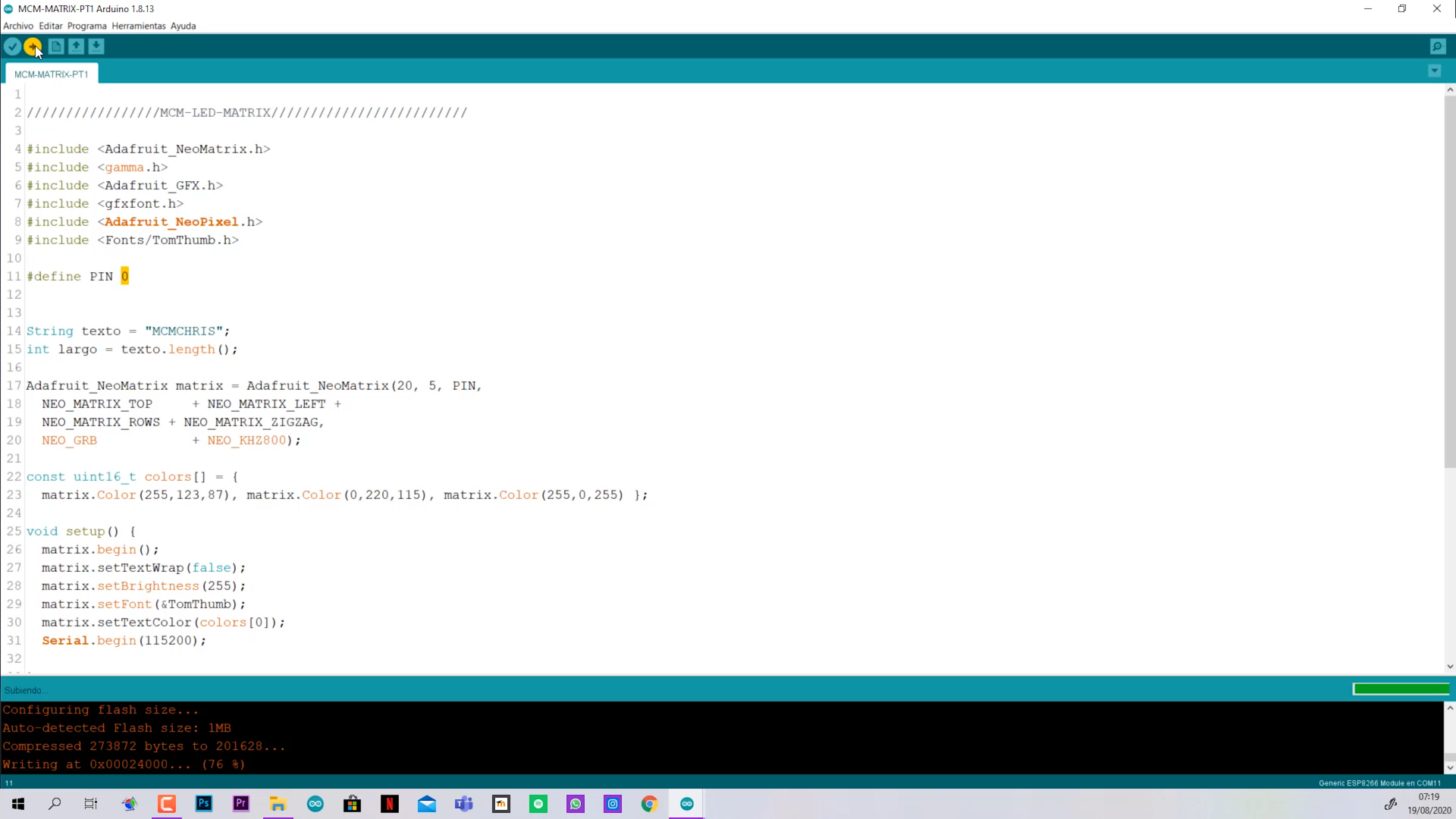
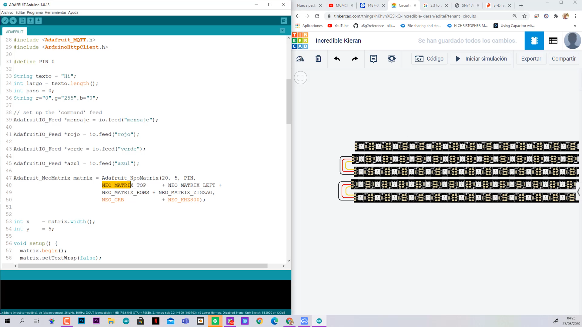
- Change the "HOLA" with the text you want to show.
- Verifiy that you are connecting the LEDs on PIN #.
- Adjust the brightness.
- Edit the colors of the text.
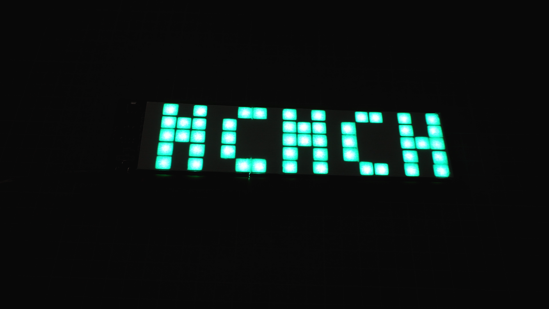
- Upload and Enjoy.
Note the last image: If you are placing the LEDs diffent than me, please adjust those options in the Code.