DIY RGB Paper Lamp Using ESP8266 and Blynk
by Kiteretsu in Circuits > Arduino
943 Views, 3 Favorites, 0 Comments
DIY RGB Paper Lamp Using ESP8266 and Blynk
In the era of IoT (Internet of Things), home automation has become a popular topic of interest. A significant part of home automation is lighting control, and RGB lamps are an excellent way to add color and ambiance to any room. In this project, we will create an RGB lamp based on the ESP8266 Wi-Fi module and the Blynk mobile app. The ESP8266 will allow the lamp to connect to your home Wi-Fi network, and the Blynk app will allow you to control the color, brightness, and effects of the lamp from your smartphone. This project is perfect for anyone who wants to add a touch of color to their home and learn more about IoT and programming.
Downloads
Supplies
- ESP8266 Wi-Fi module (NodeMCU)
- RGB LED strip
- 12V power supply (sufficient to power your LED strip)
- Breadboard or PCB board
- Jumper wires
- BC547 transistor (or IRFZ44N or equivalent)
- 10k ohm resistor
- Blynk mobile app
- Paper/Plastic Cups x2 (make sure light can easily pass through it)
- Thick paper strips
- Transparent tape
- Scissors
Creating the Base

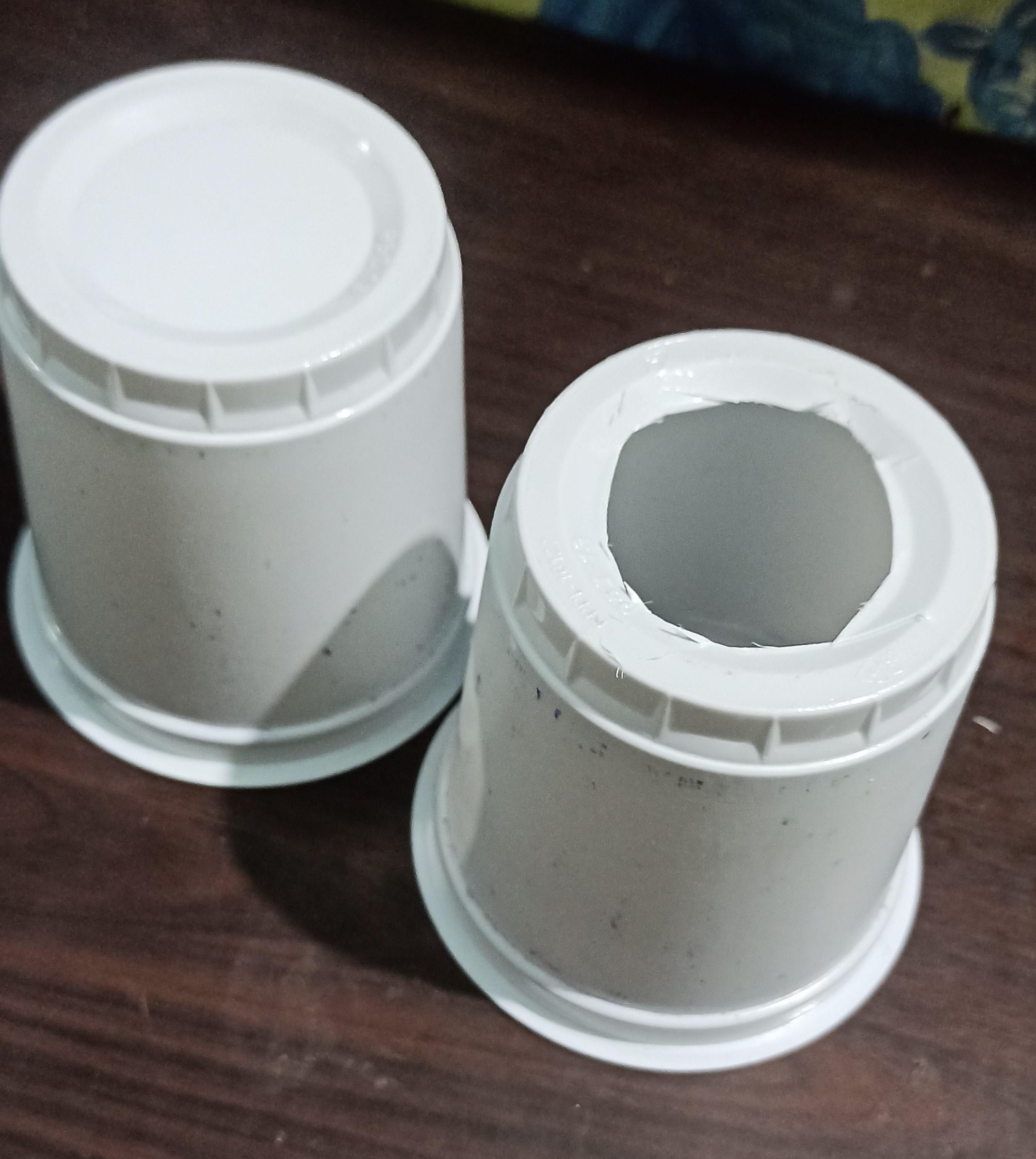

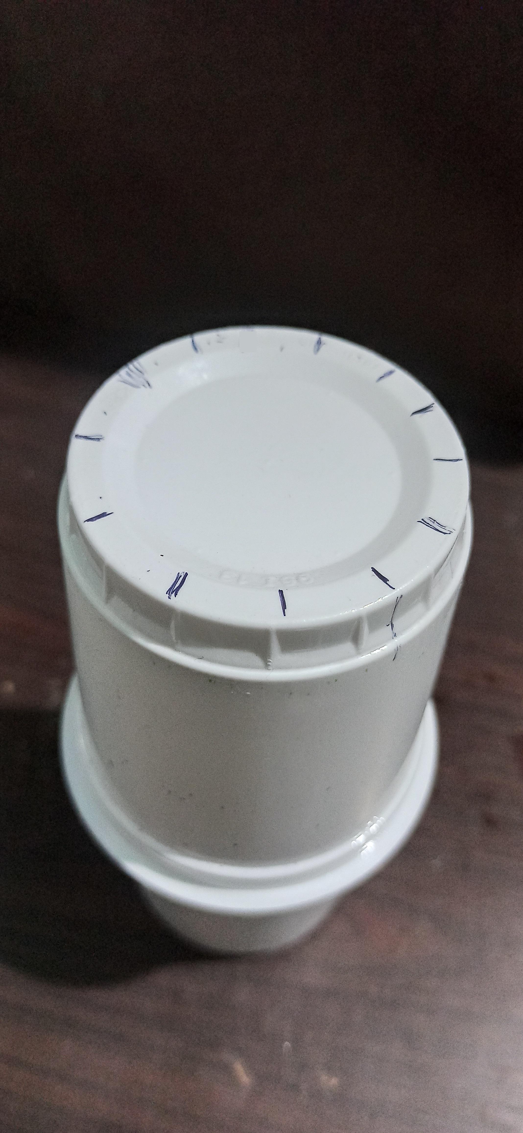
Take two identical cups, clear the bottom face of one, place them together one over the other and glue them together, divide the bottom face of cup into 12 equal parts.
Add Paper Strips to the Base
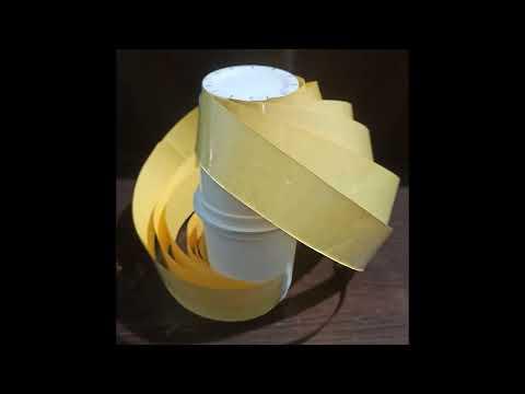

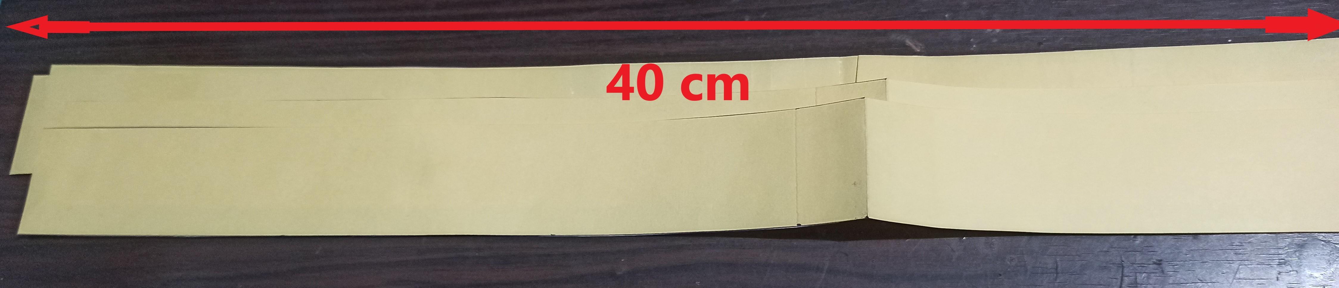
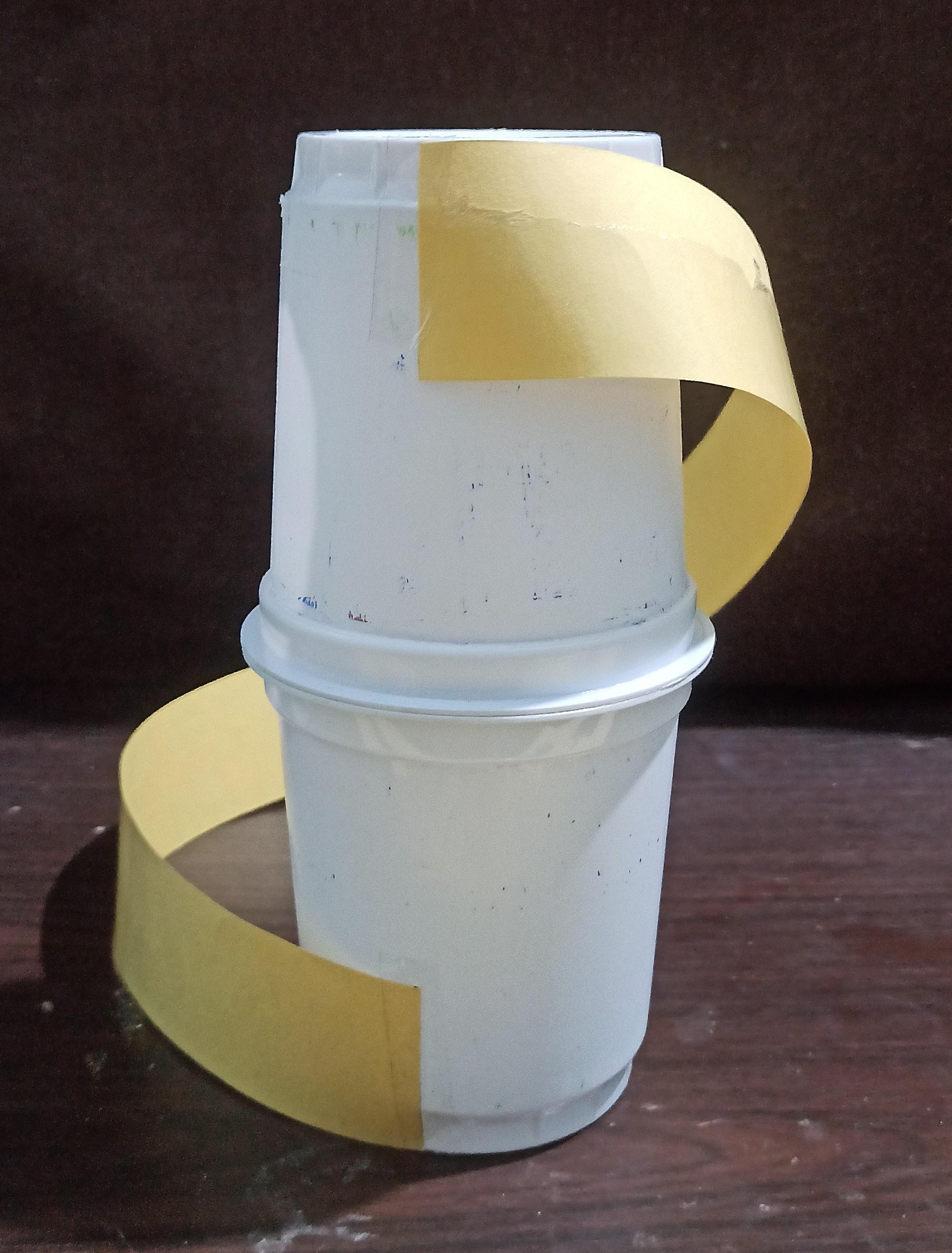
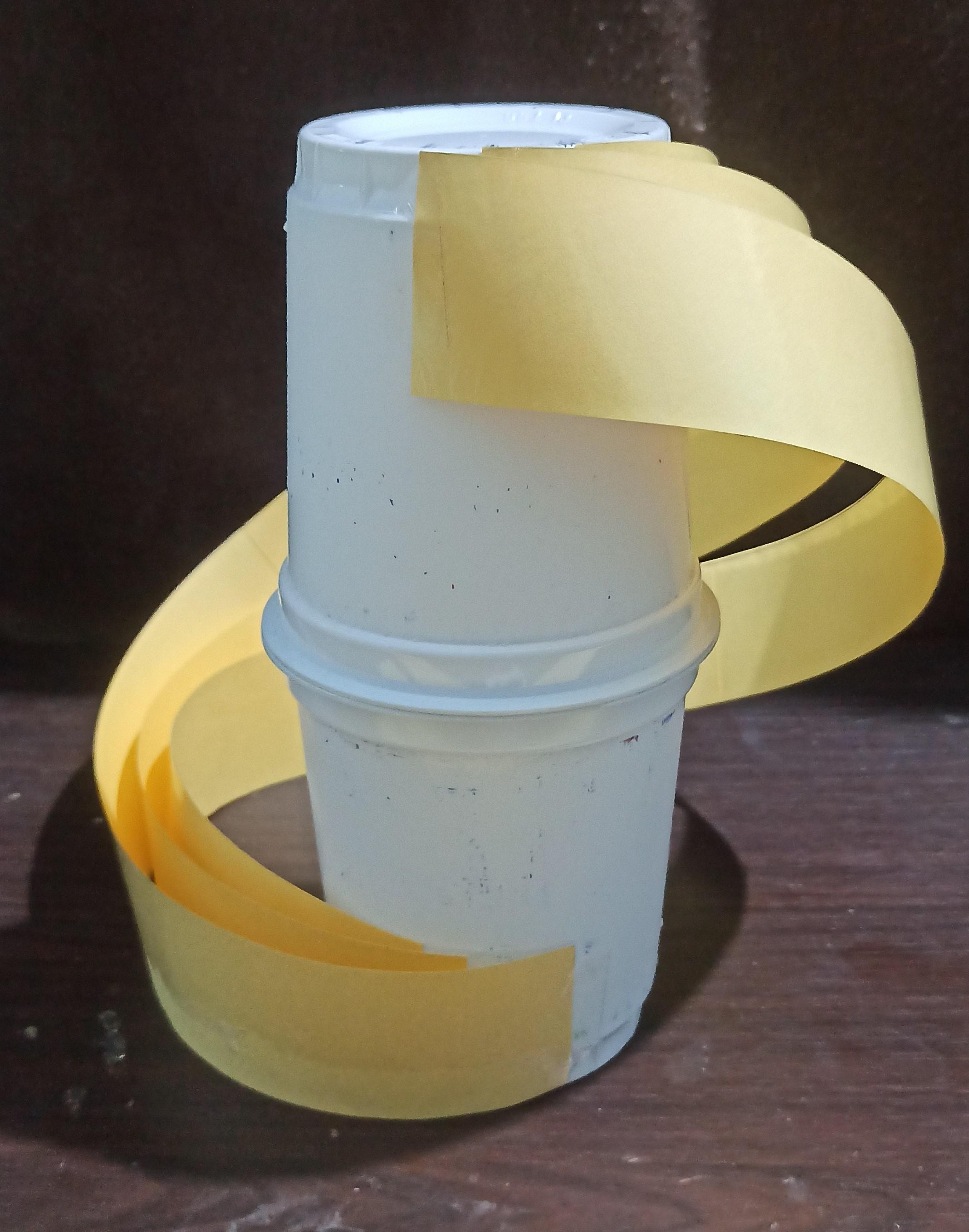
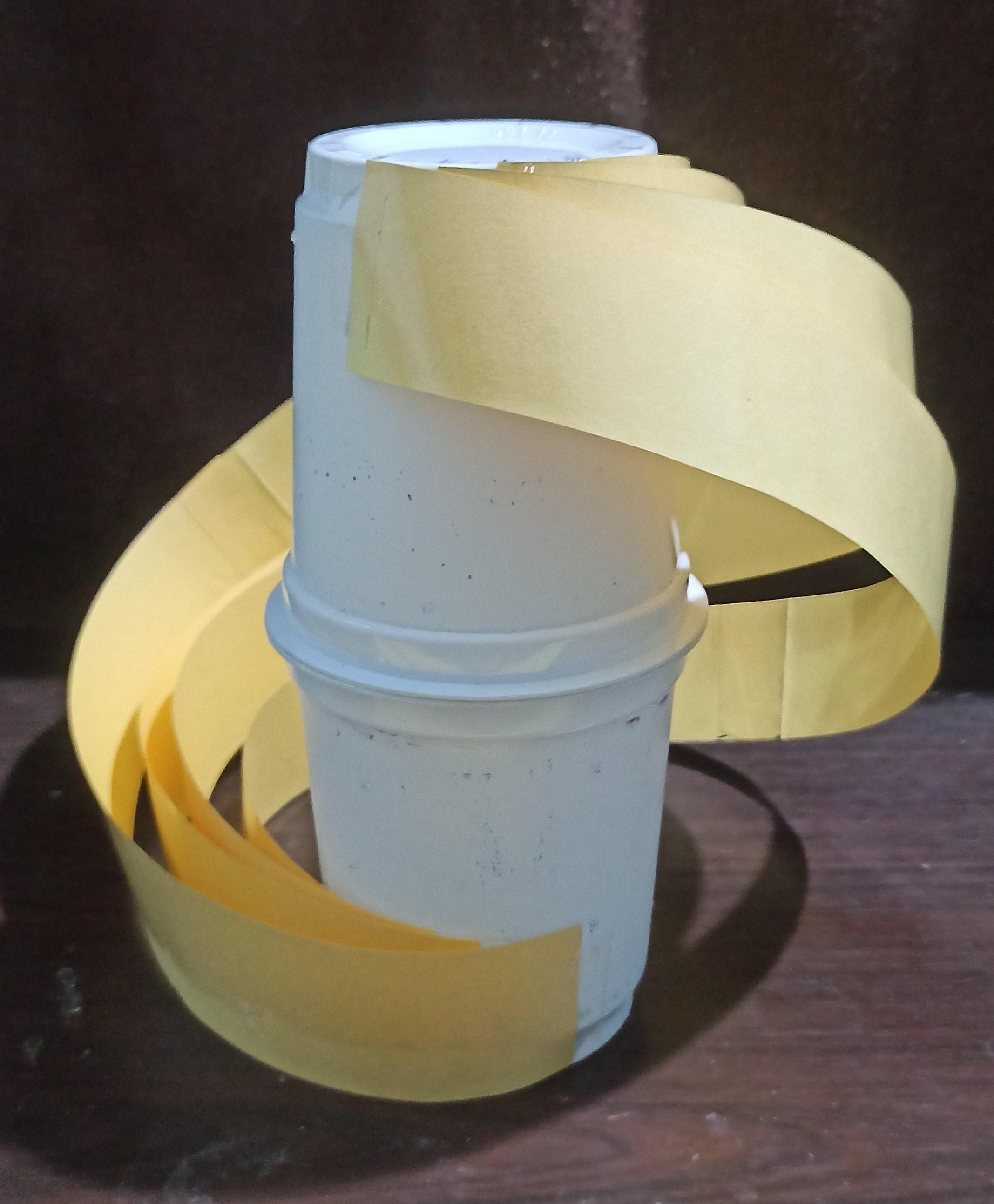
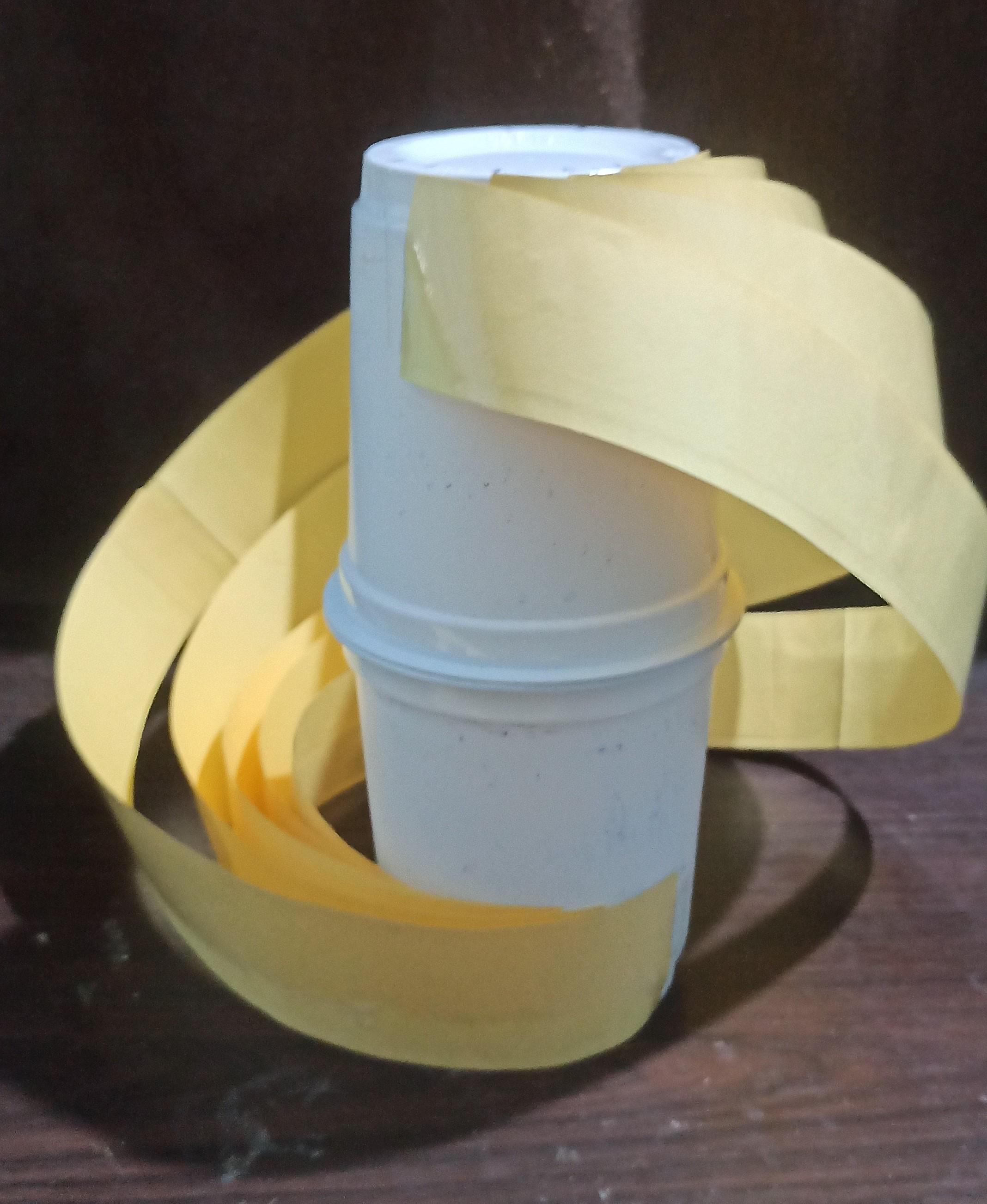
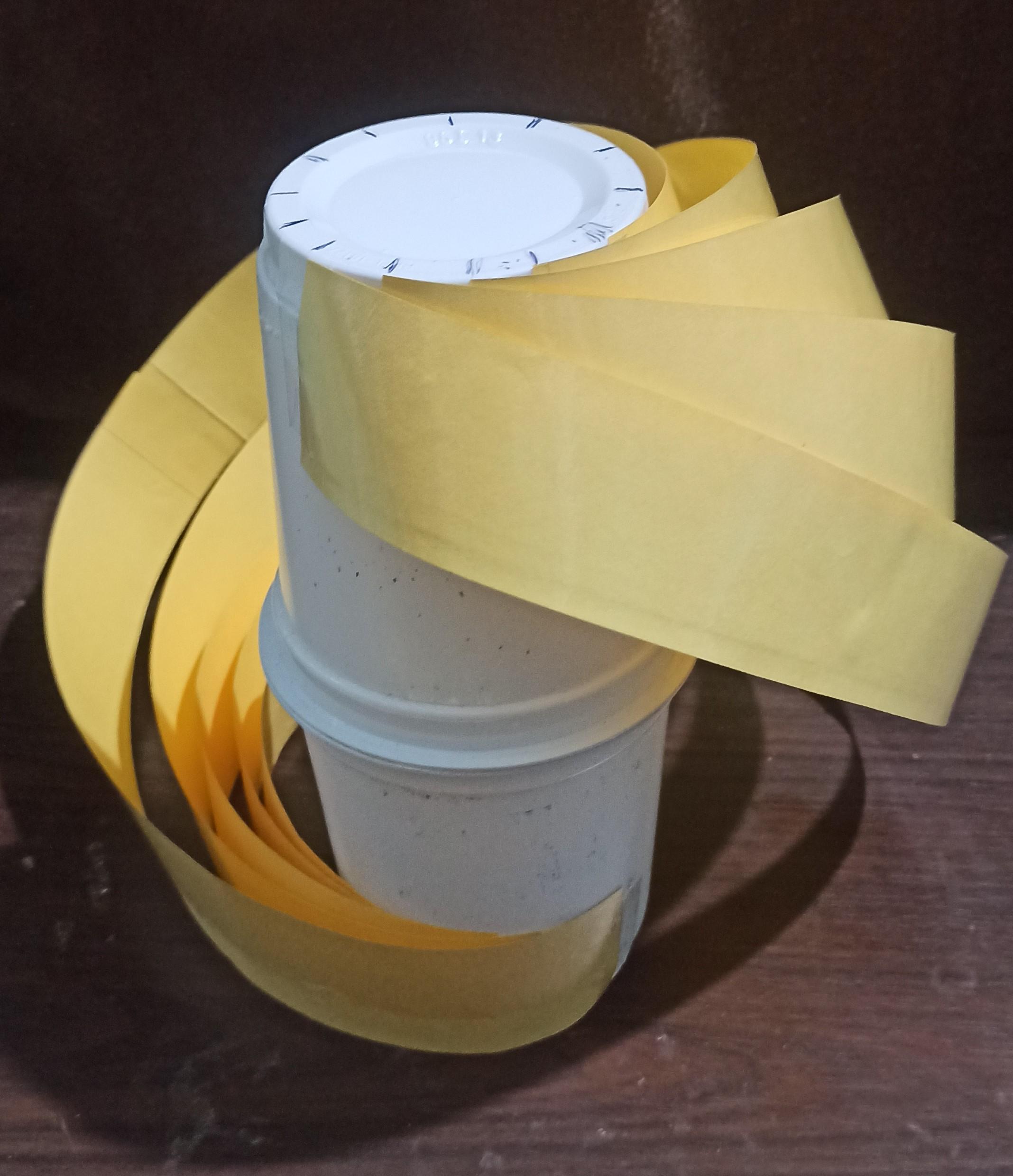
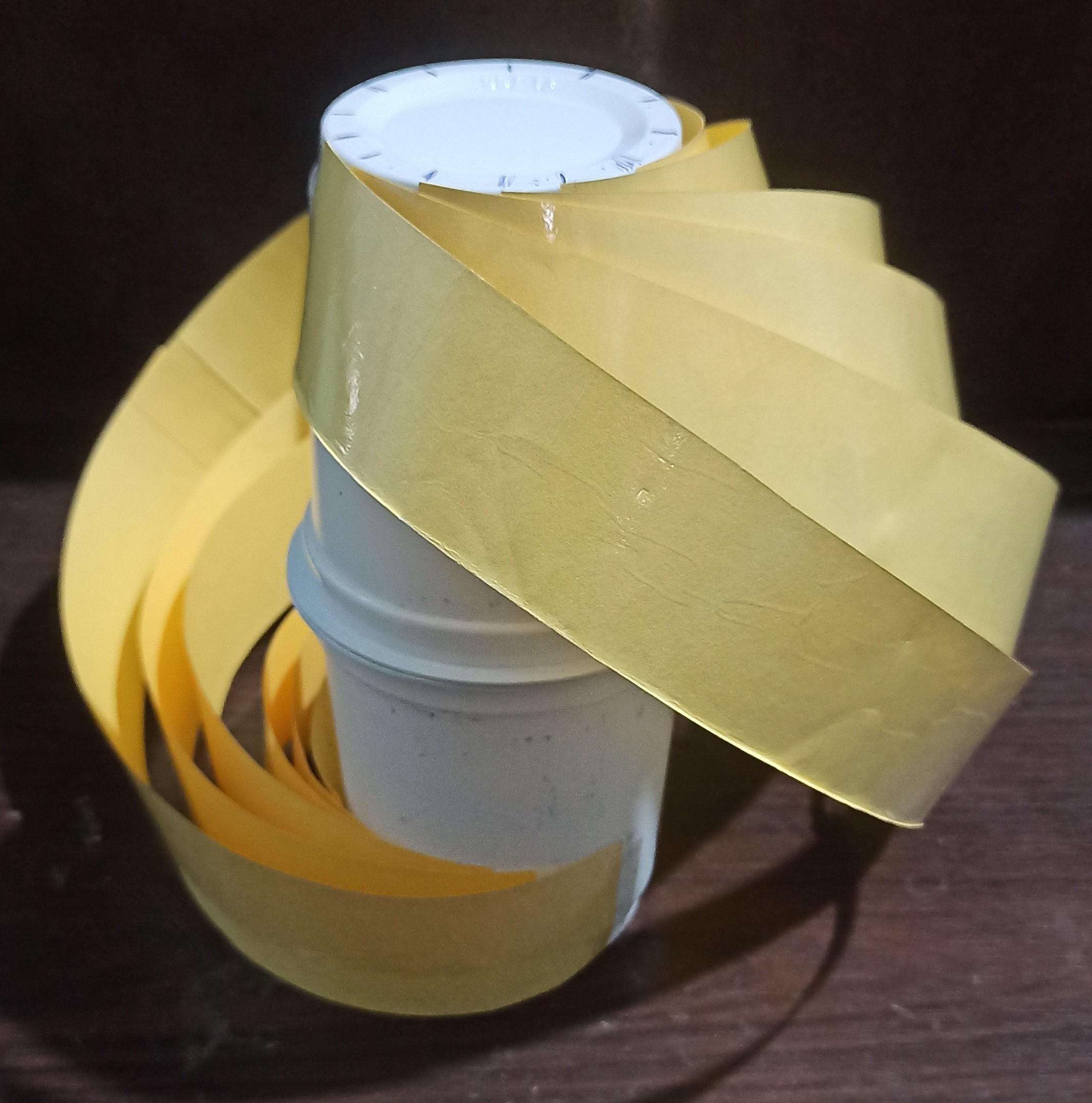
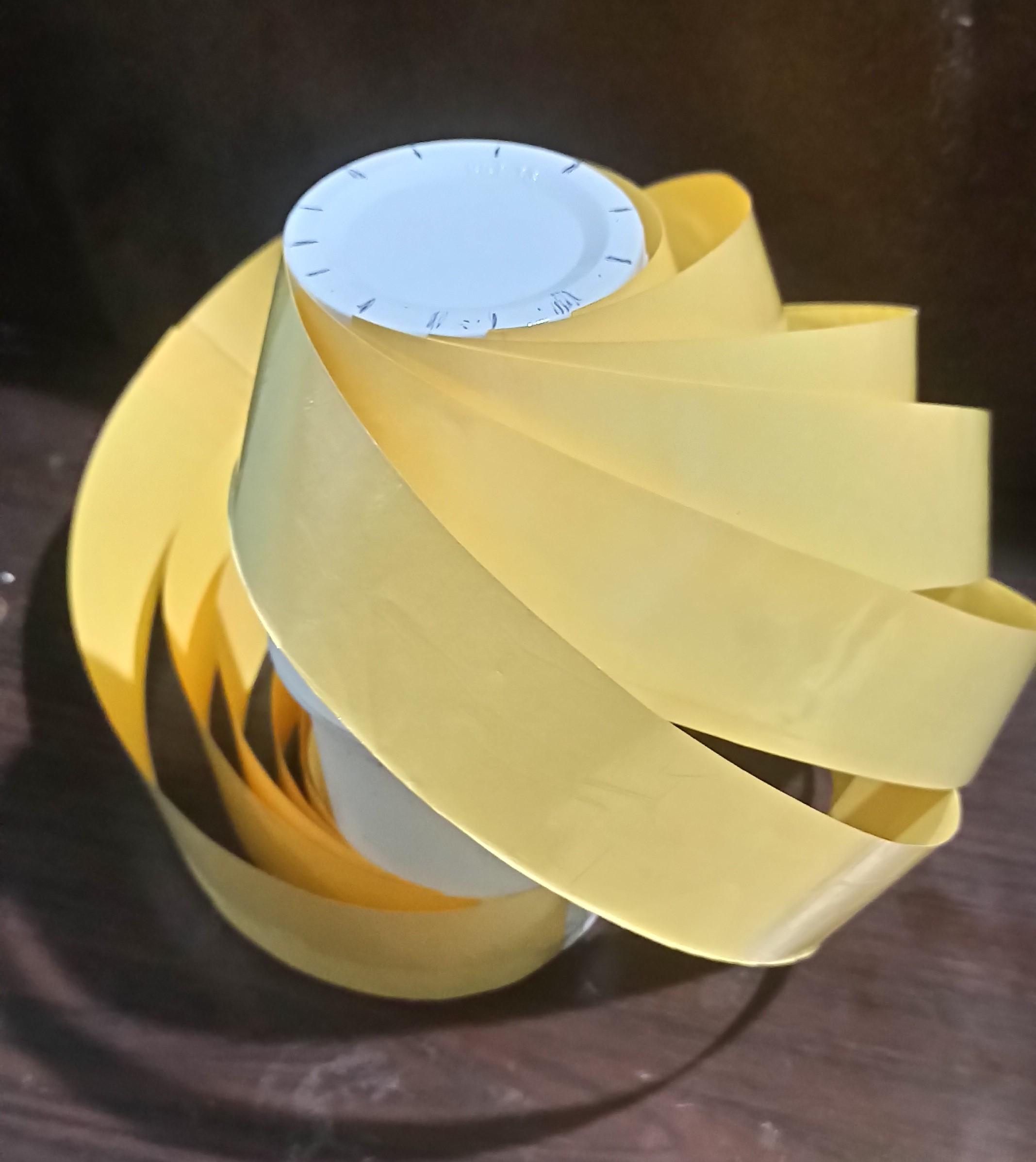
Take length of the strips as twice the length of the cup structure, and width 4 cm would be enough, attach strips one by one at a time, make sure to end the strip in same line at which head of the strip is started (i.e. head and tail of the strips must be in same line), repeat this pattern for next strips and so on, to complete the lamp body.
Designing the Circuit
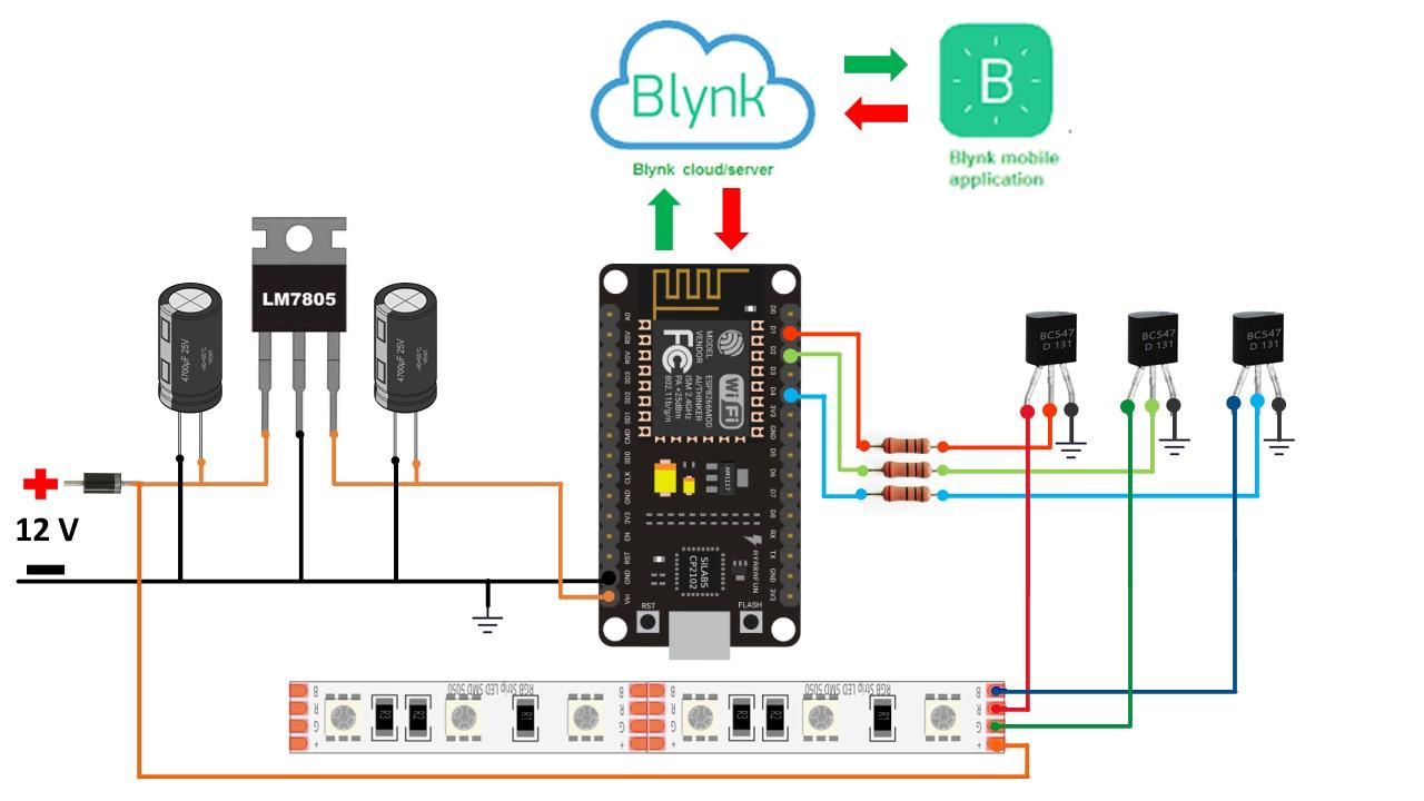
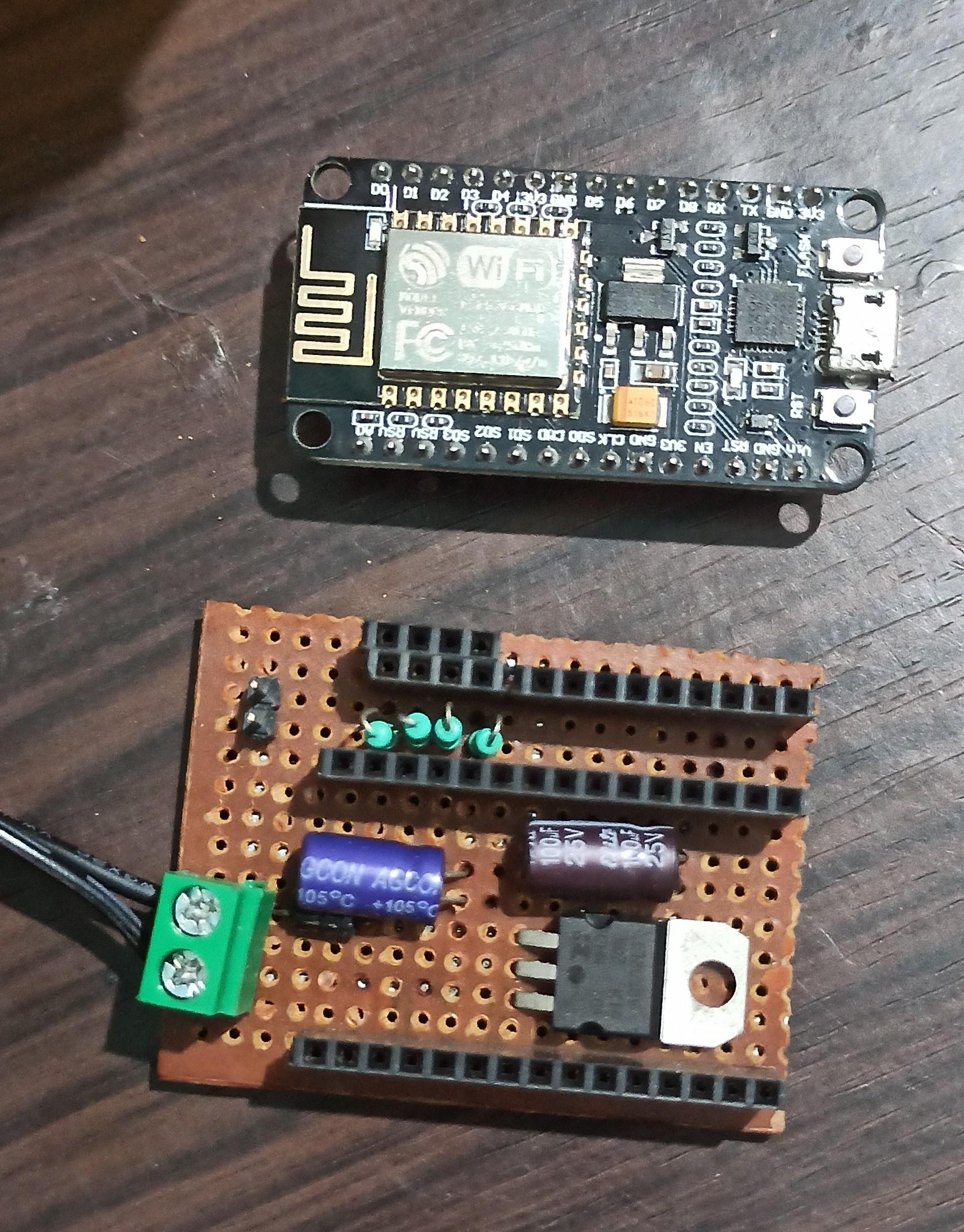
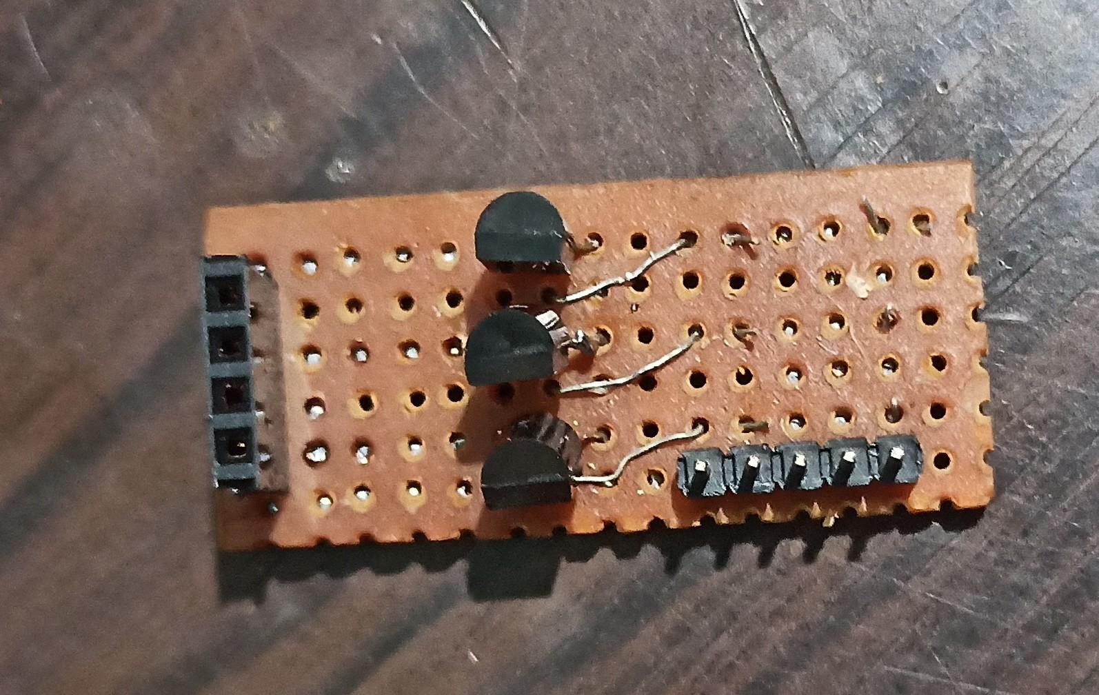
For my RGB lamp project, I created a separate board for the NodeMCU and transistor components. This allows me to reuse the NodeMCU board for future projects and easily swap out other components. By having a dedicated NodeMCU board, I can use it for other projects without sacrificing the RGB lamp setup, maximizing the versatility and longevity of my components.
Setting Up the Blynk Cloud
.png)
.png)
.png)
.png)
.png)
.png)
.png)
.png)
.png)
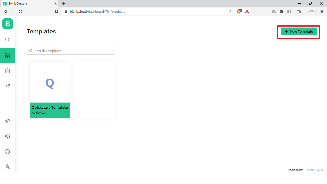
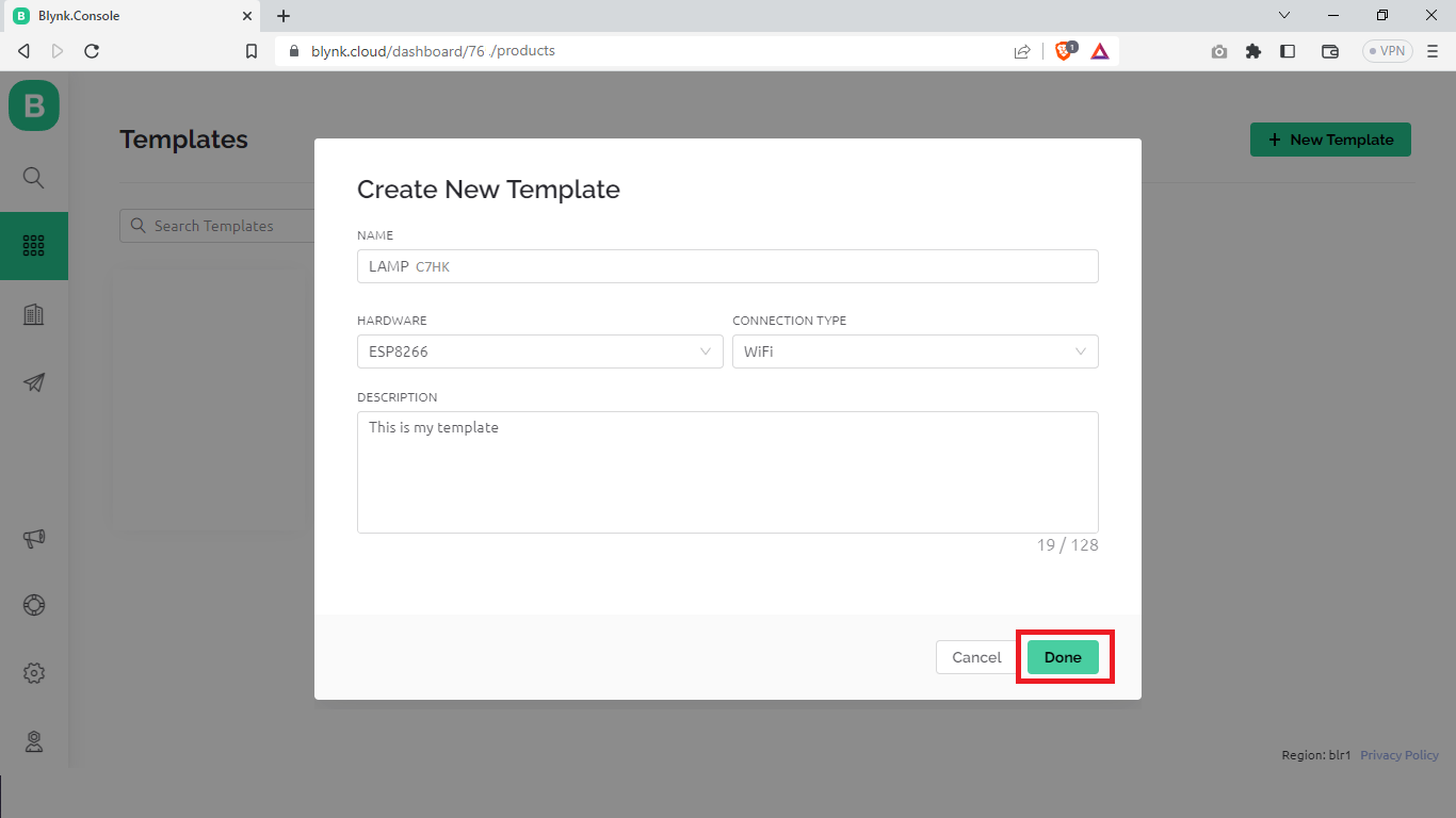
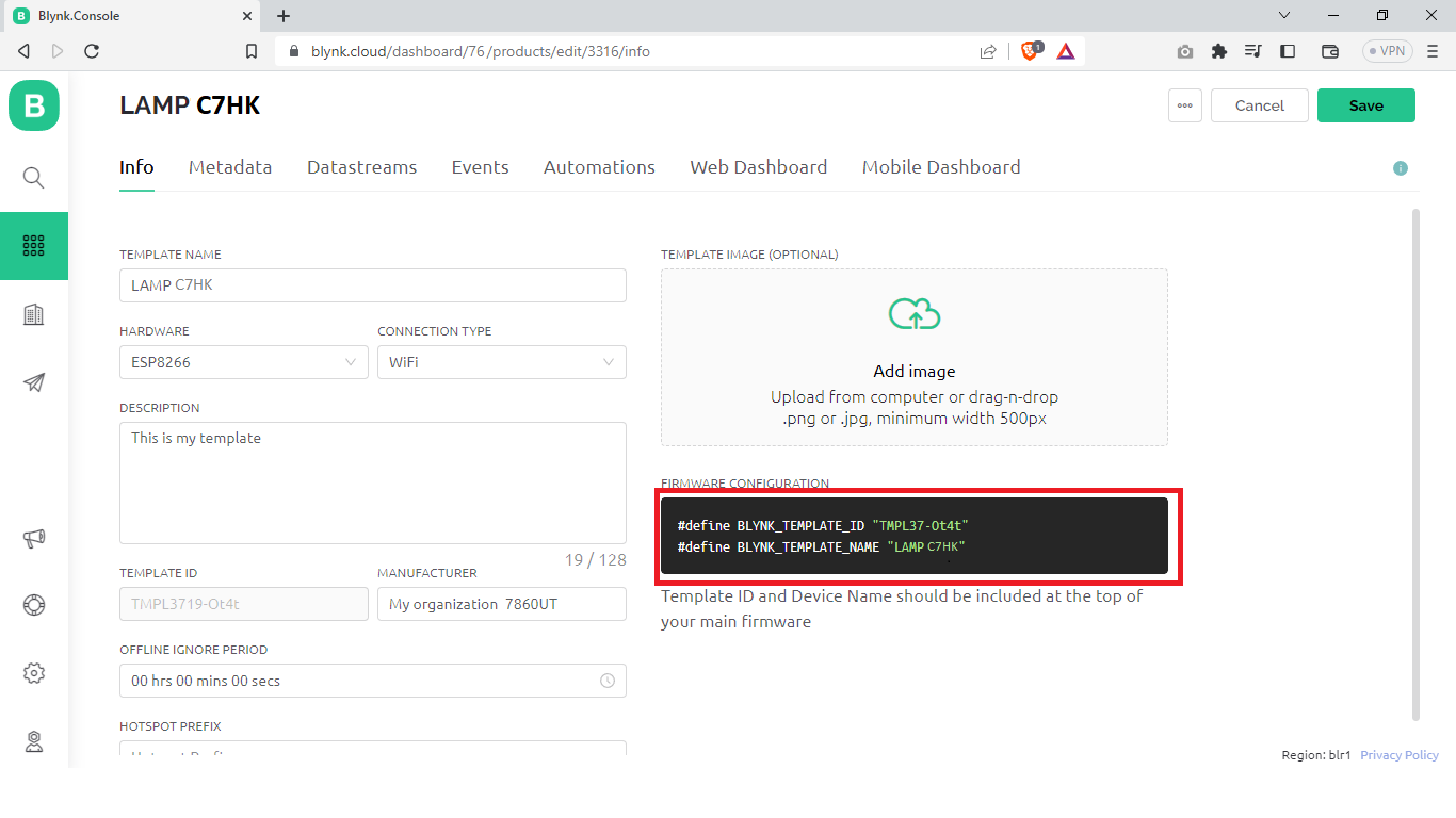
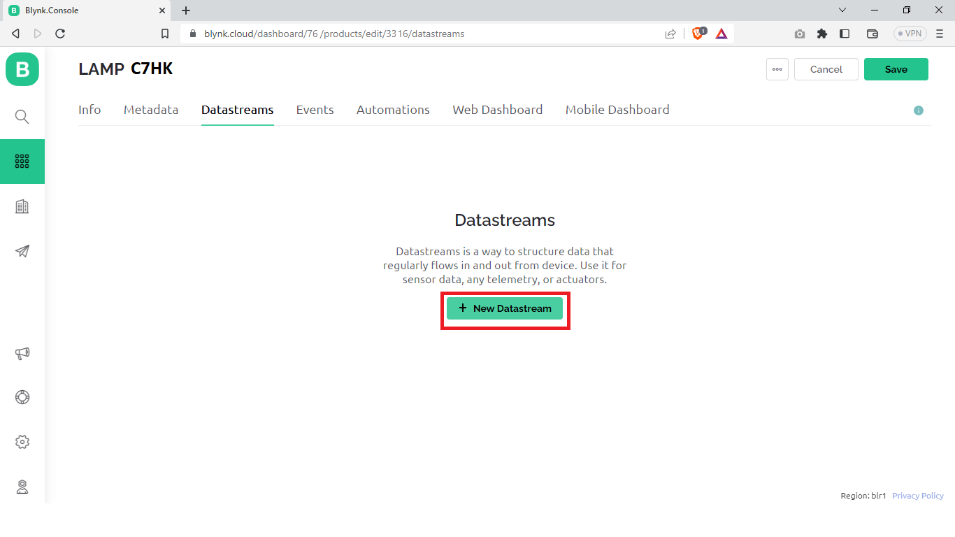
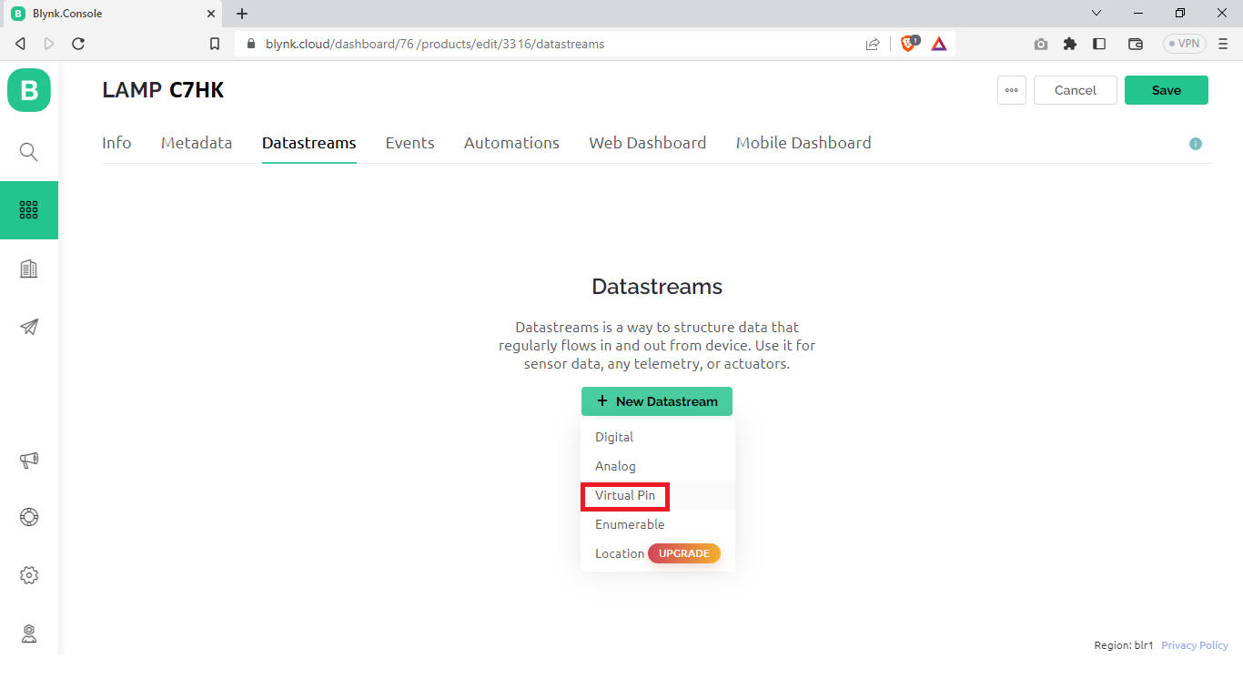
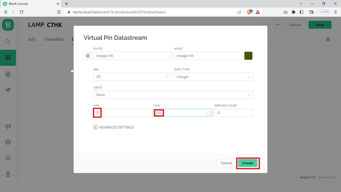
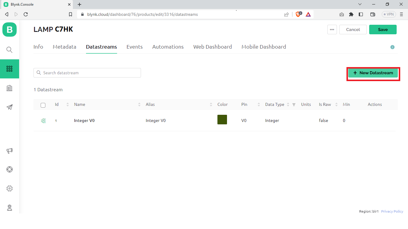
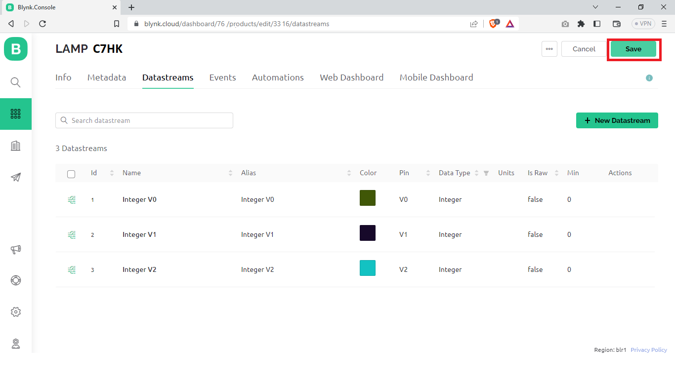
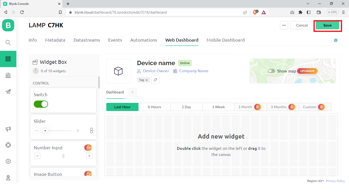
Login to your Blynk Cloud and create a new template, and add the datastream needed, I need 3 virtual pins for this project so I had created 3 datastream, make sure too copy your template ID and template Name, you need to enter these details while writing the code.
Writing the Code
.png)
.png)
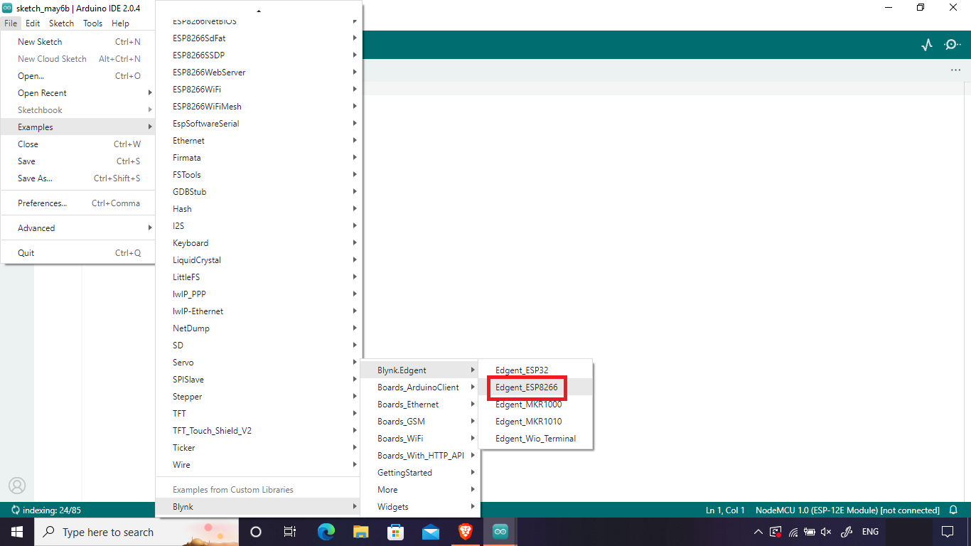
Install the Blynk library
Go to Examples > Blynk > Blynk Edgent > Edgent_ESP8266
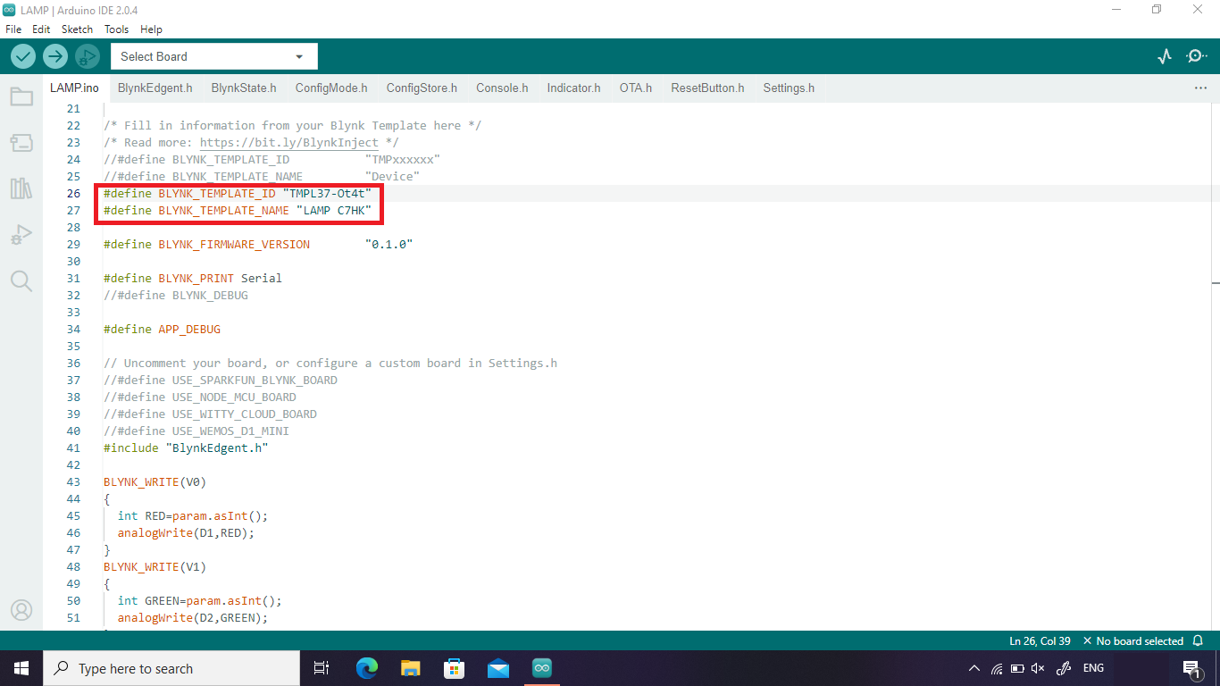
Enter the Template ID and Template Name in the code.
Downloads
Setting Up the Blynk Android App
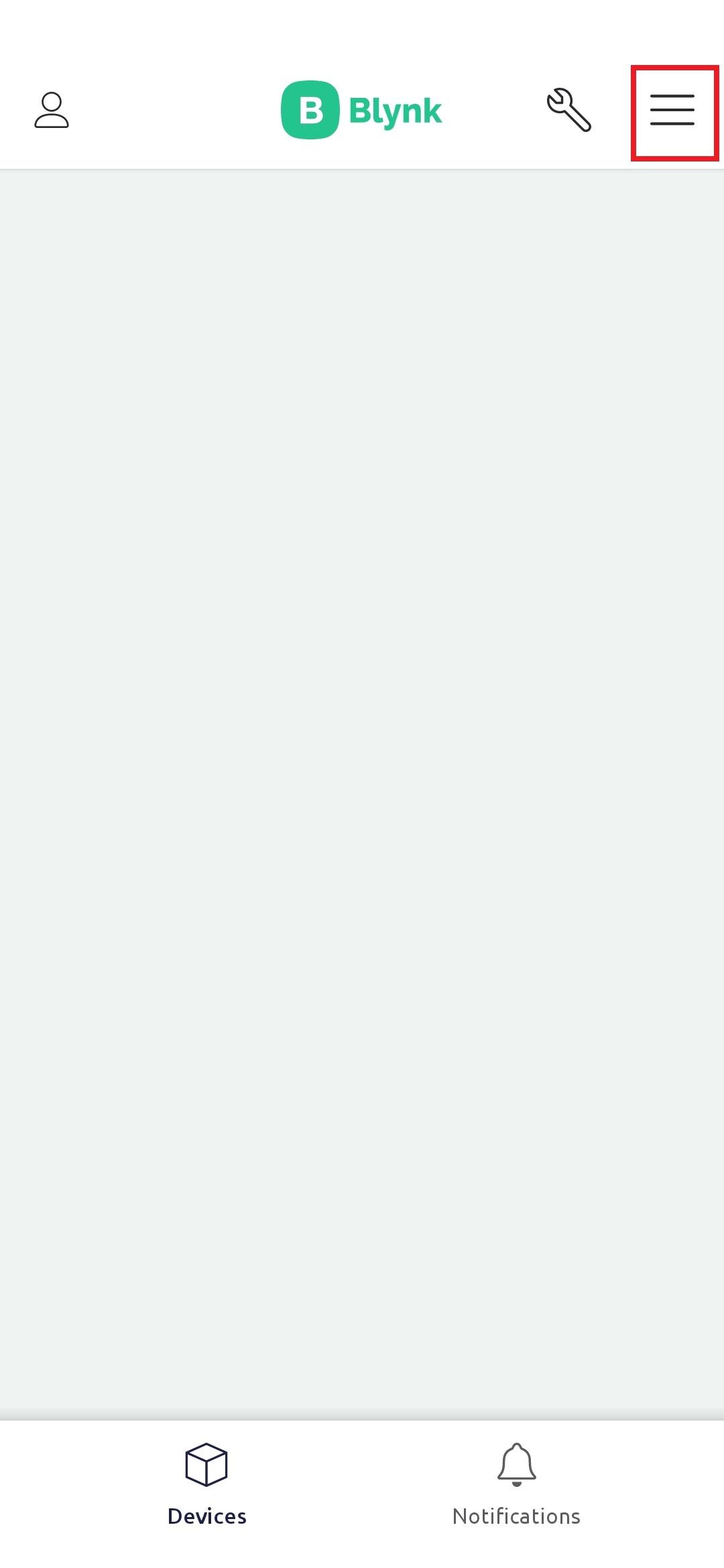
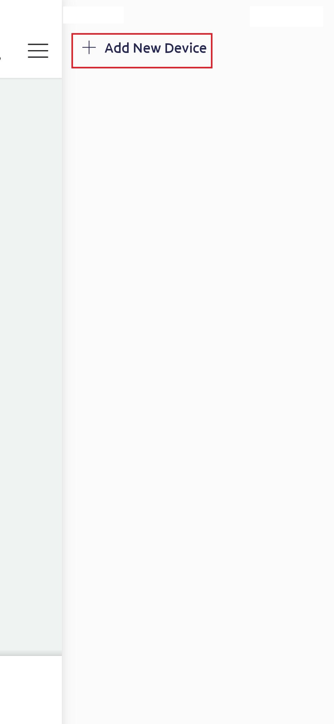
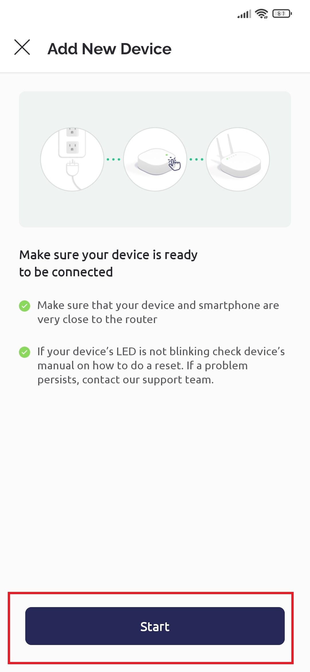
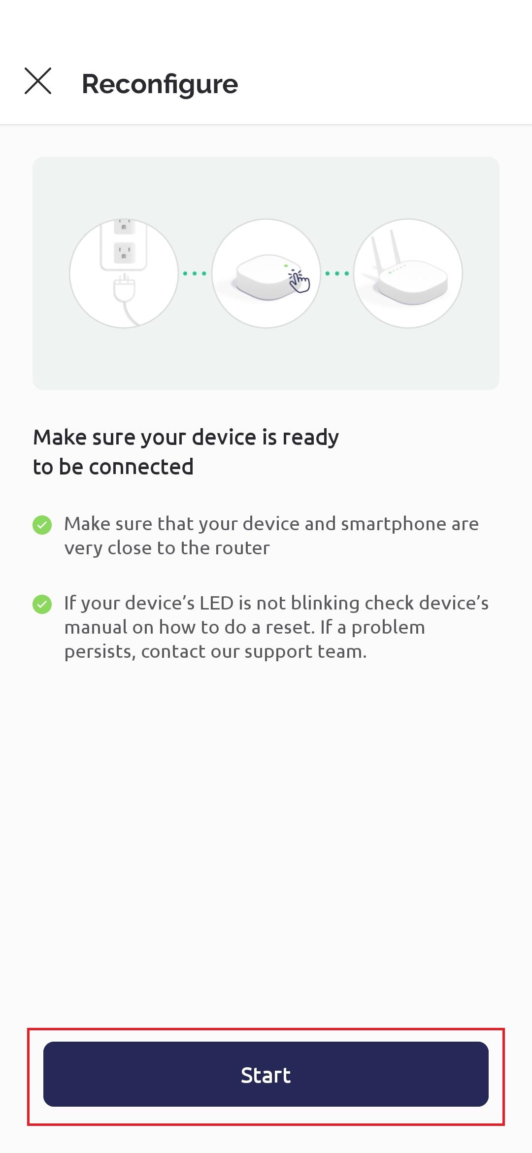
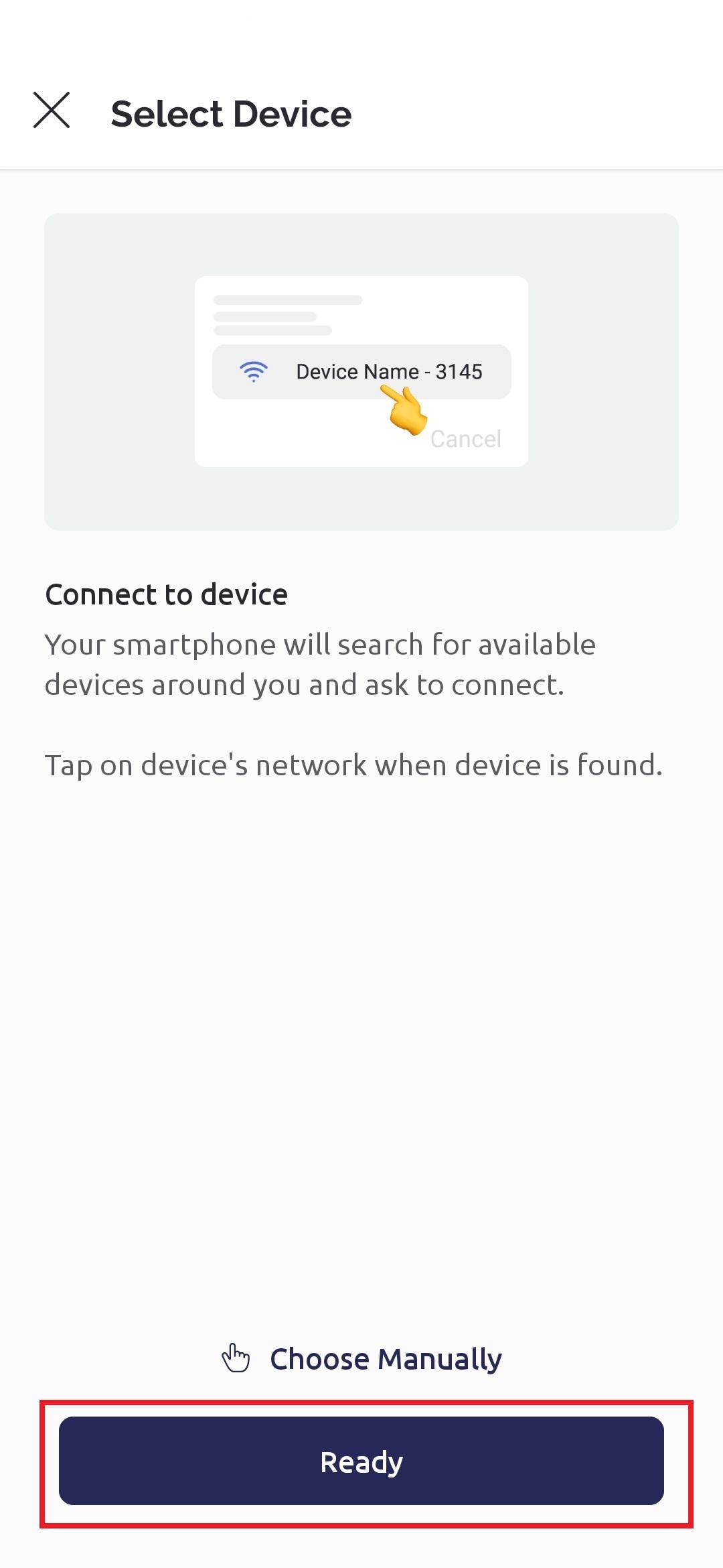
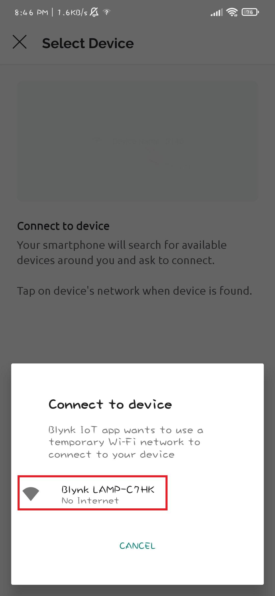
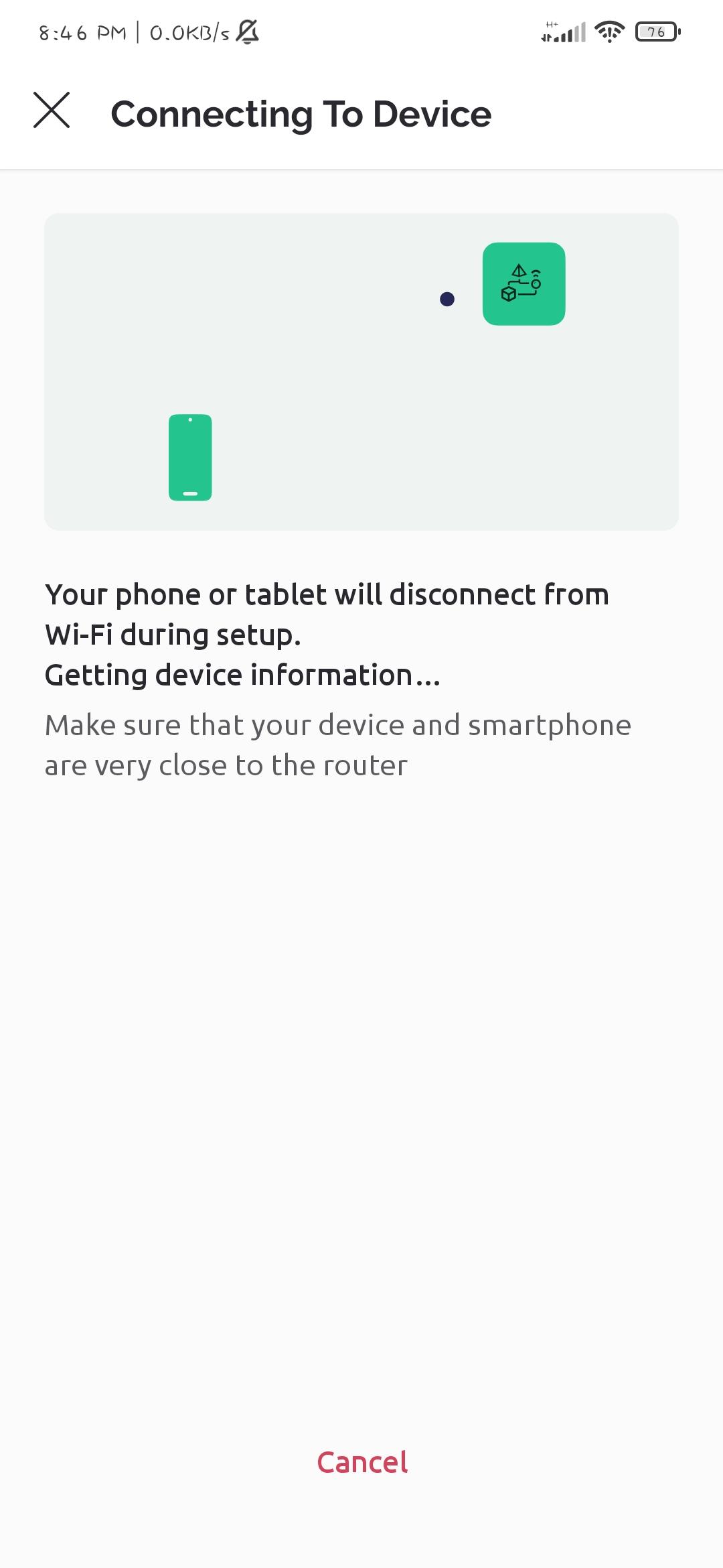
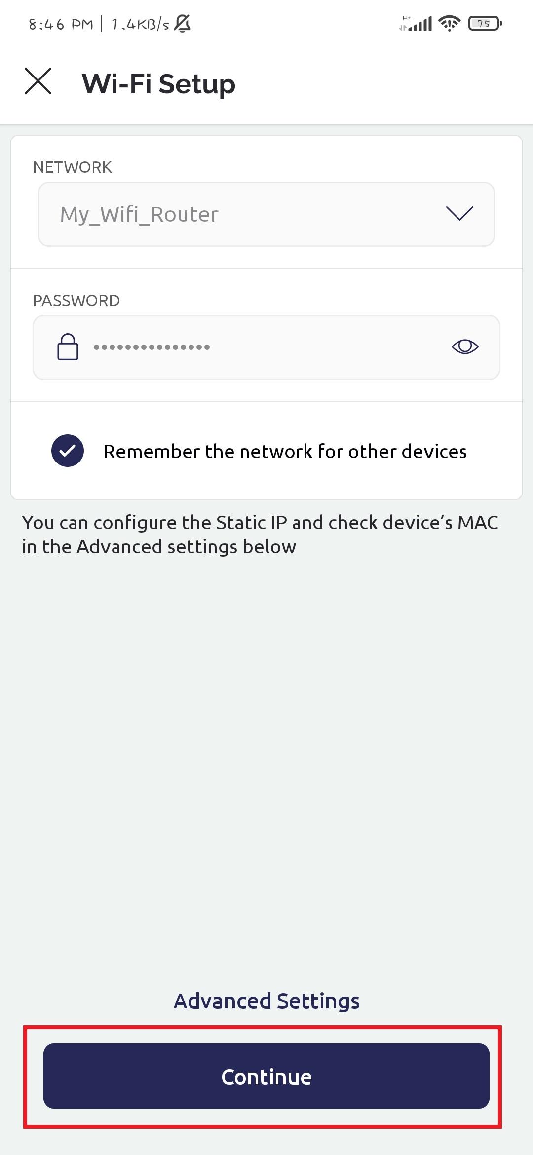
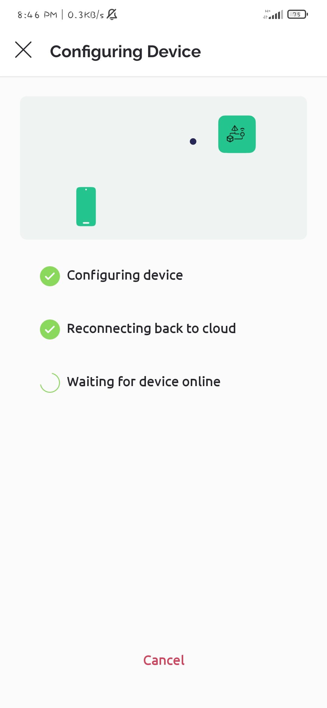
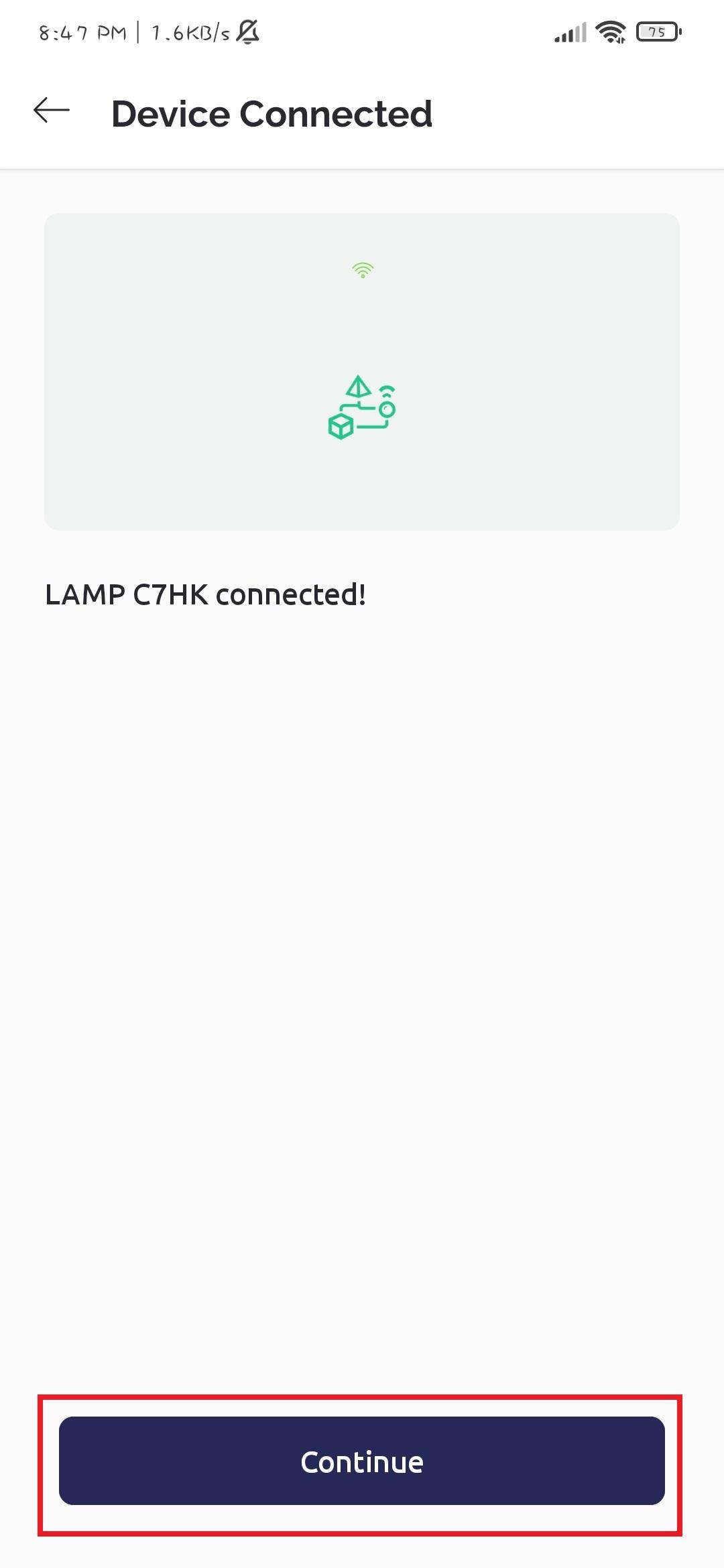
Open the Blynk app, and click on the three lines, and add a new device, while connecting the new device you will be asked to provide the WIFI credentials, and the new device (ESP board) is ready to connect to Internet.
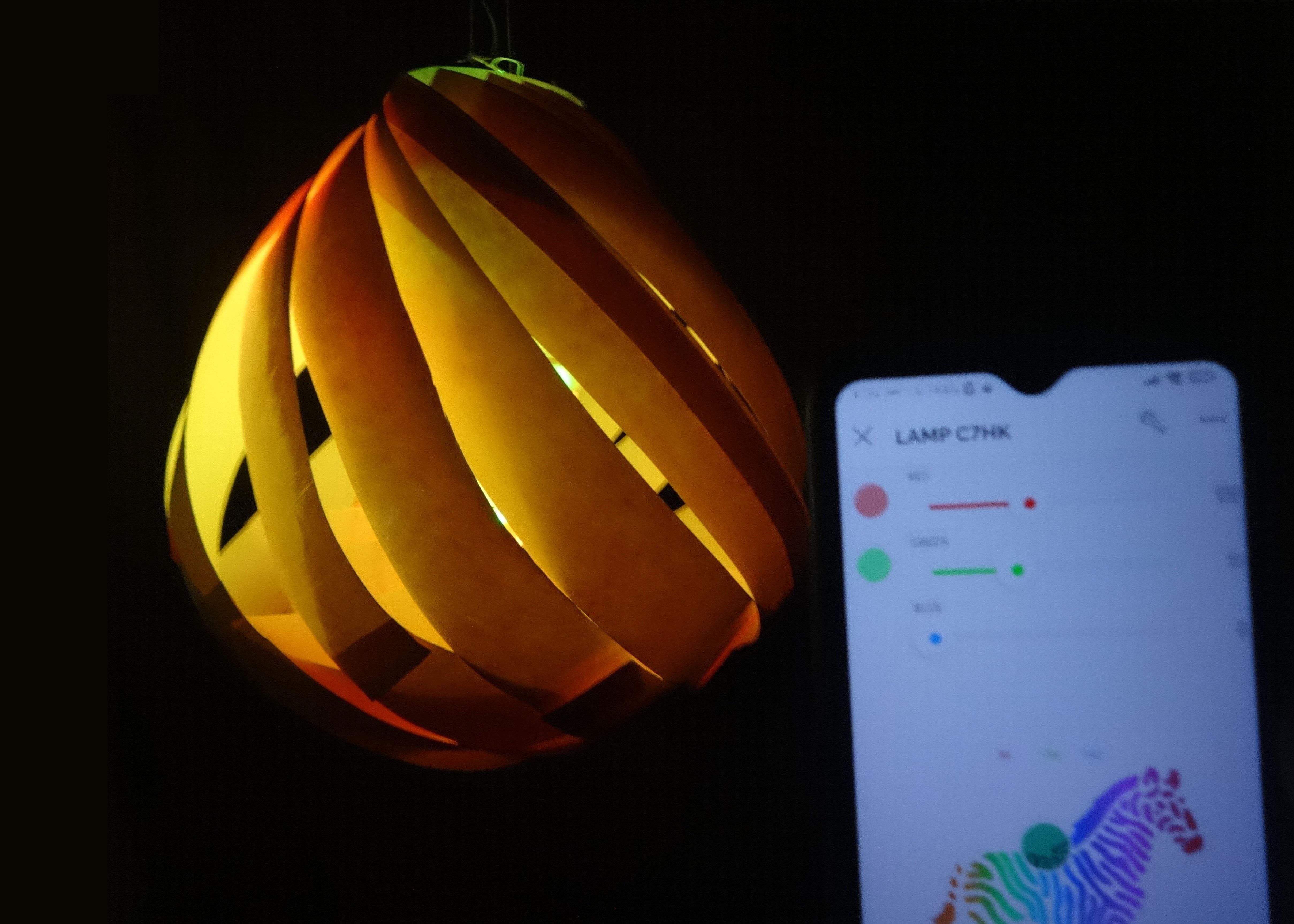
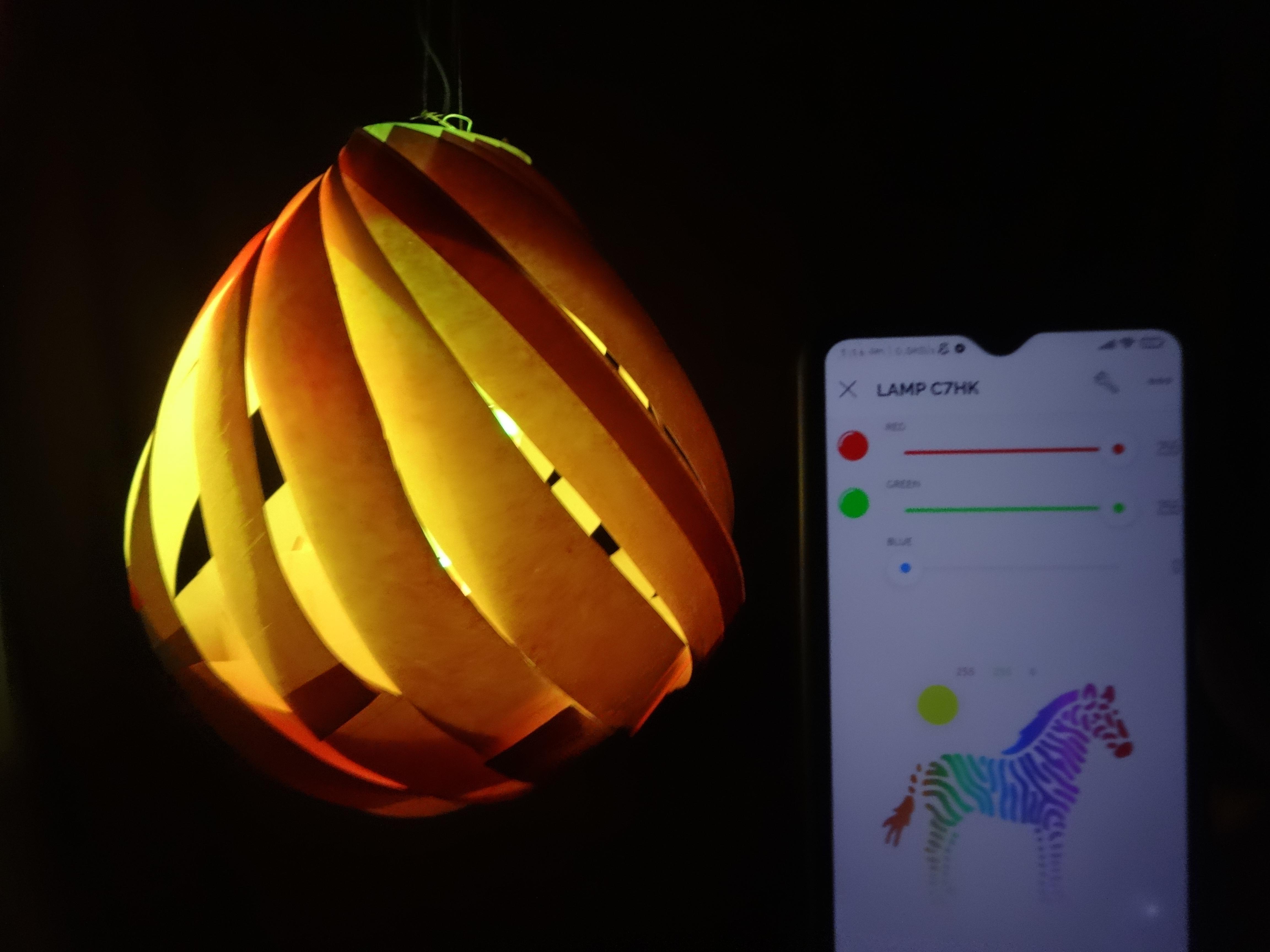
Testing the Circuit and Blynk Cloud
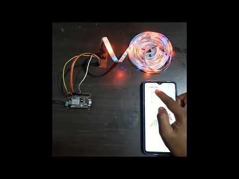
To test the RGB lamp circuit, connect the NodeMCU board to a power source and open the Blynk mobile app. Then, follow the instructions in the app to connect the NodeMCU to your Wi-Fi network and upload the code to the board. Once the code is uploaded, the LED strip should light up and respond to commands in the app. You can then test the different color and brightness settings to ensure that the circuit is working properly.
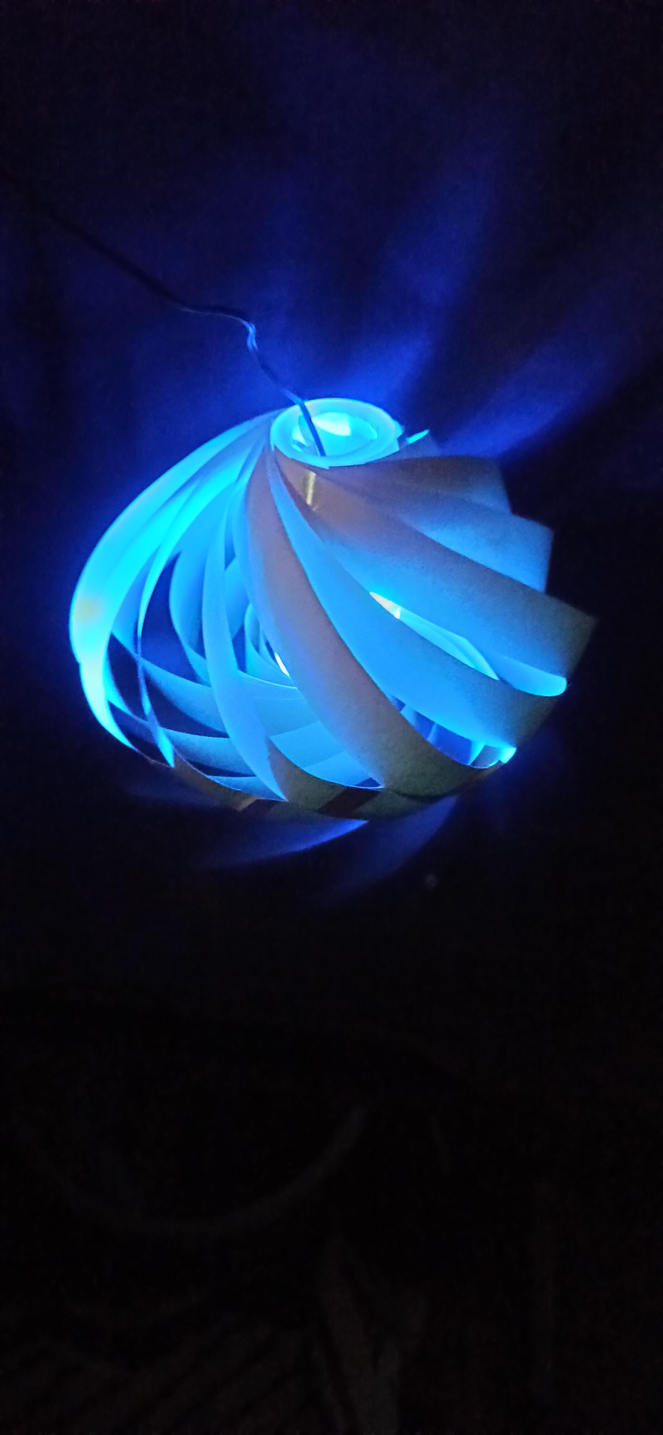
Place the Circuit and ESP8266 Board Inside the Lamp Body
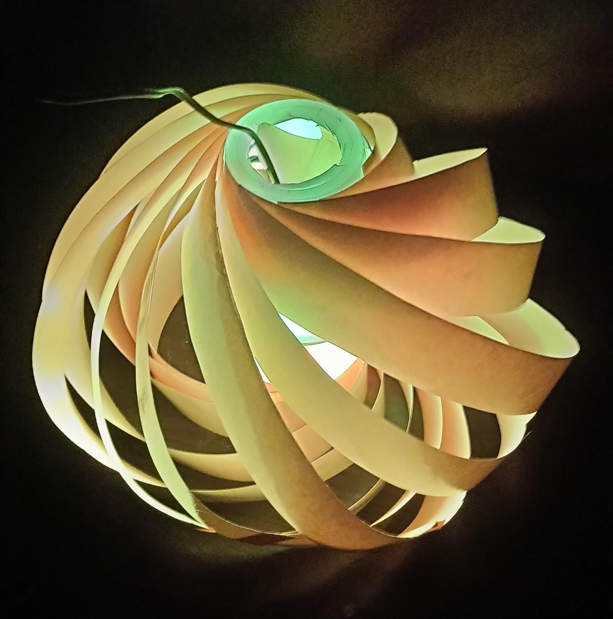
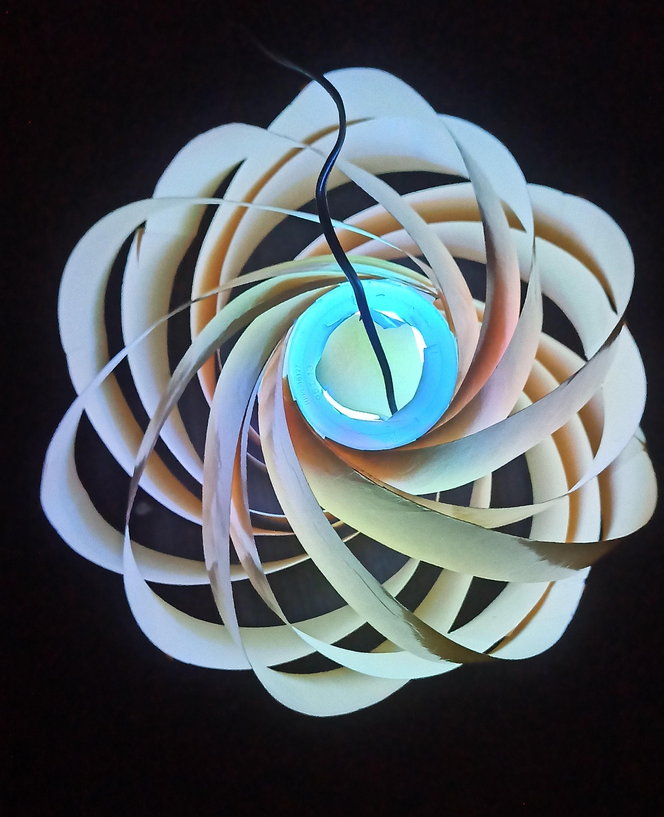
Carefully place the circuit inside the lamp
Your DIY RGB Lamp Is Ready
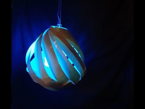
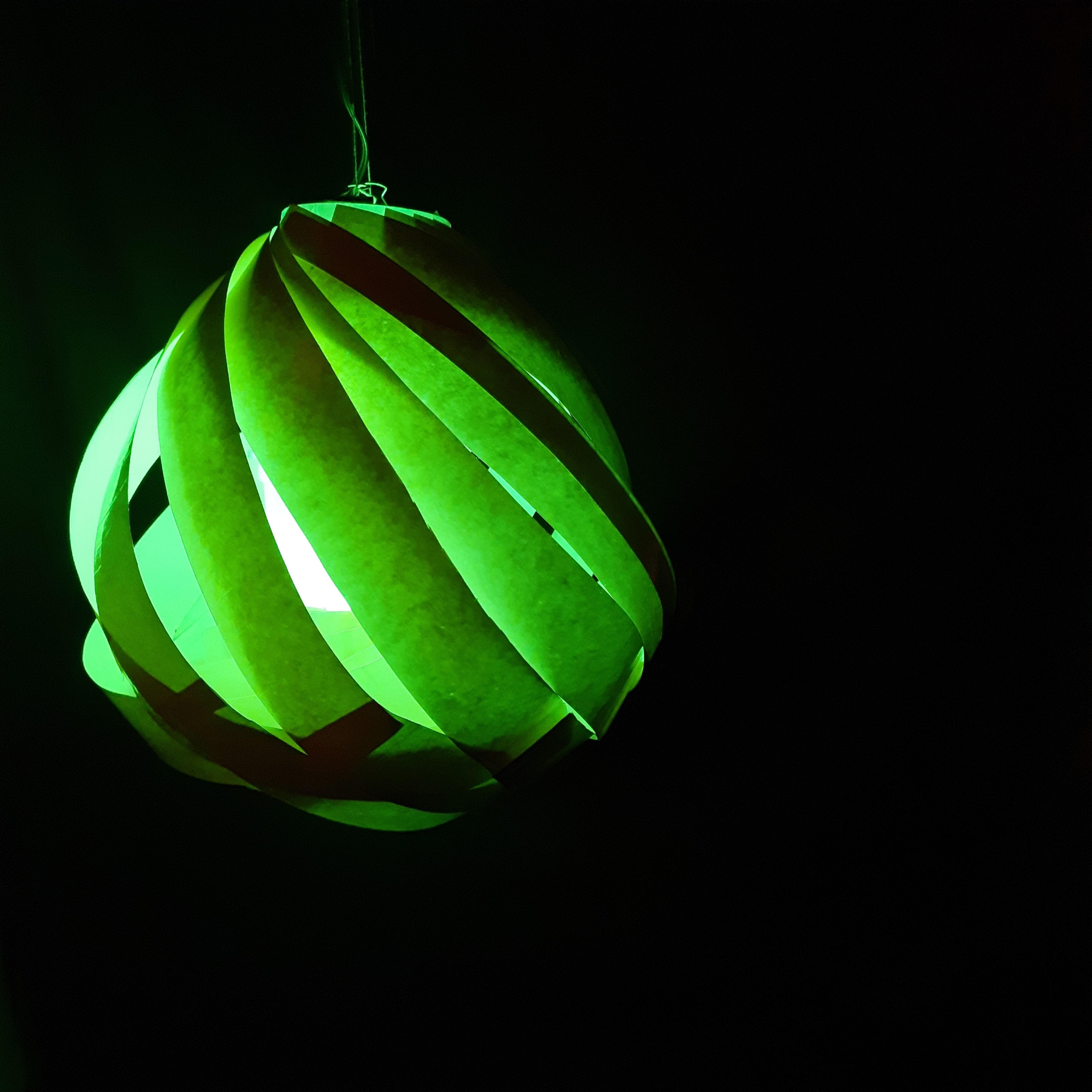
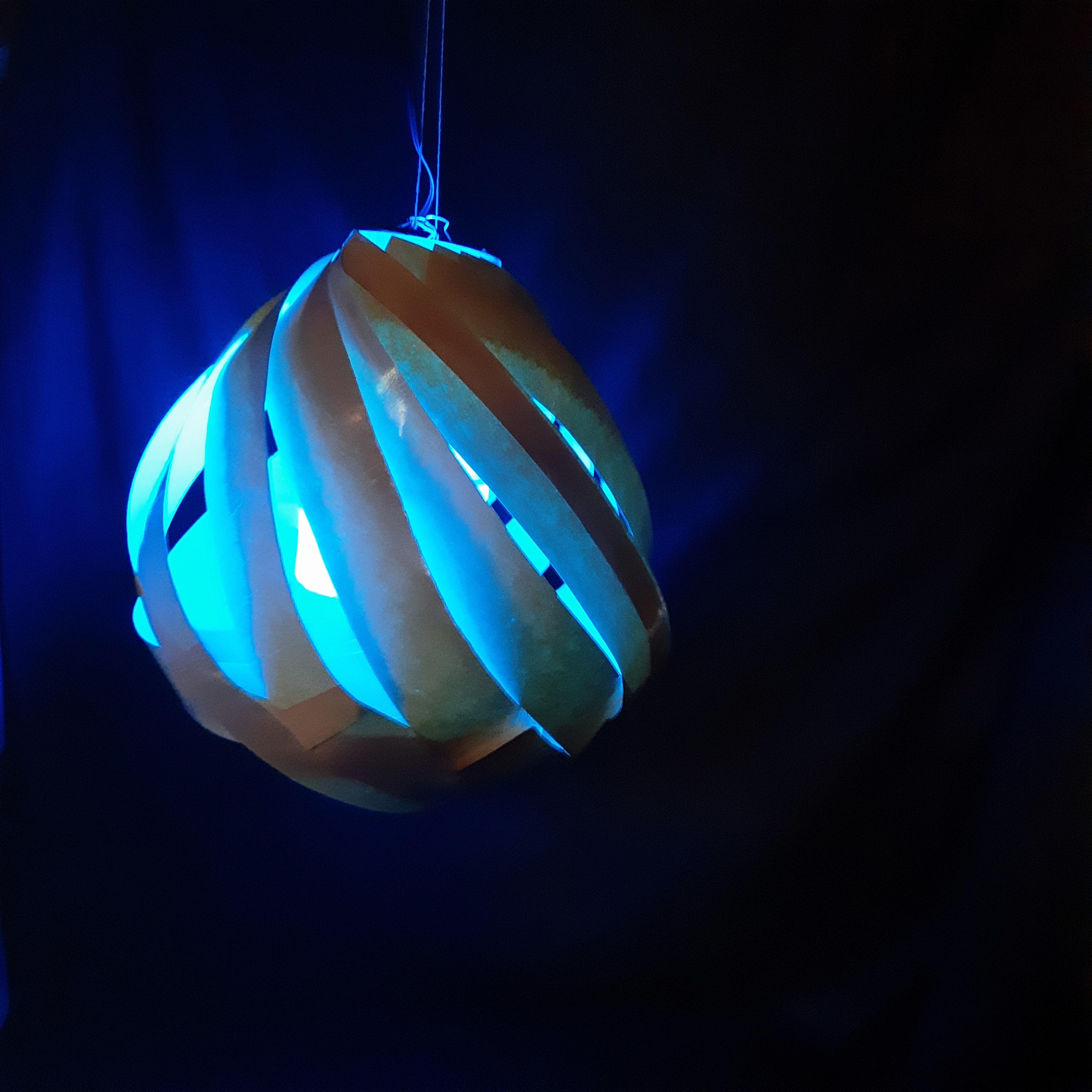
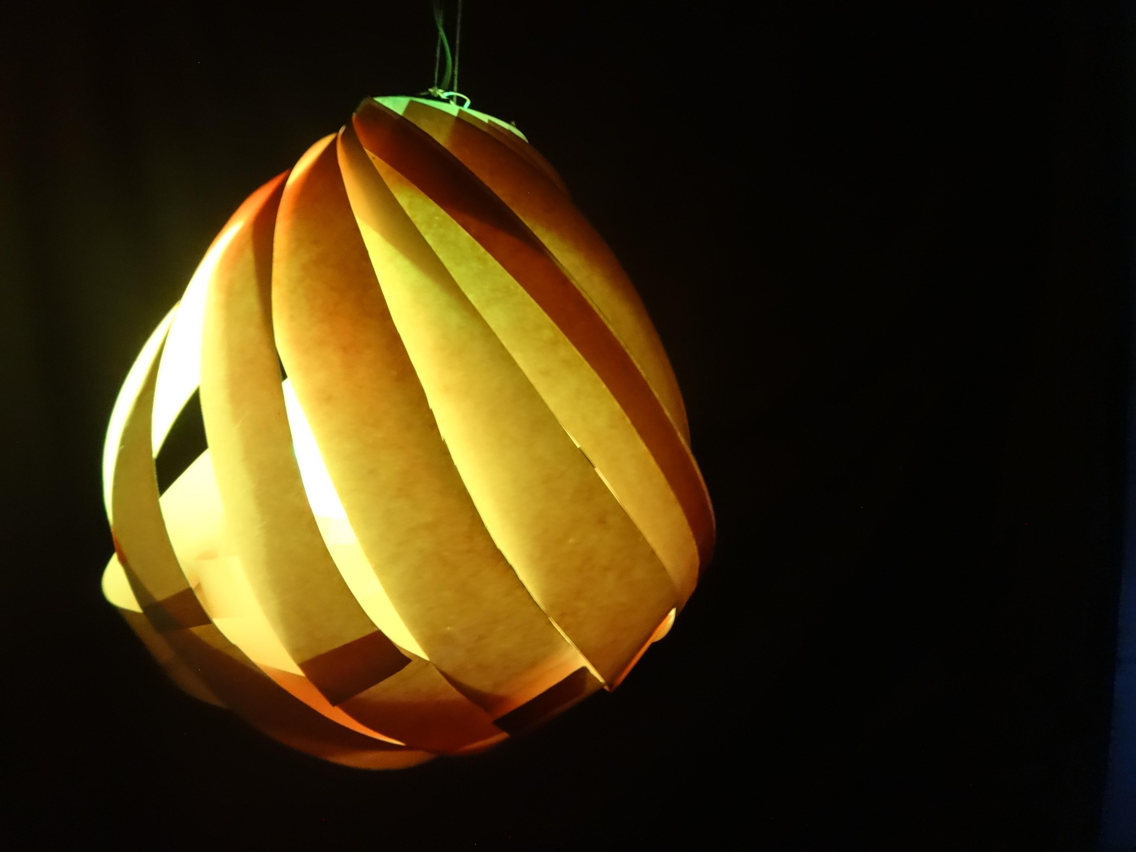
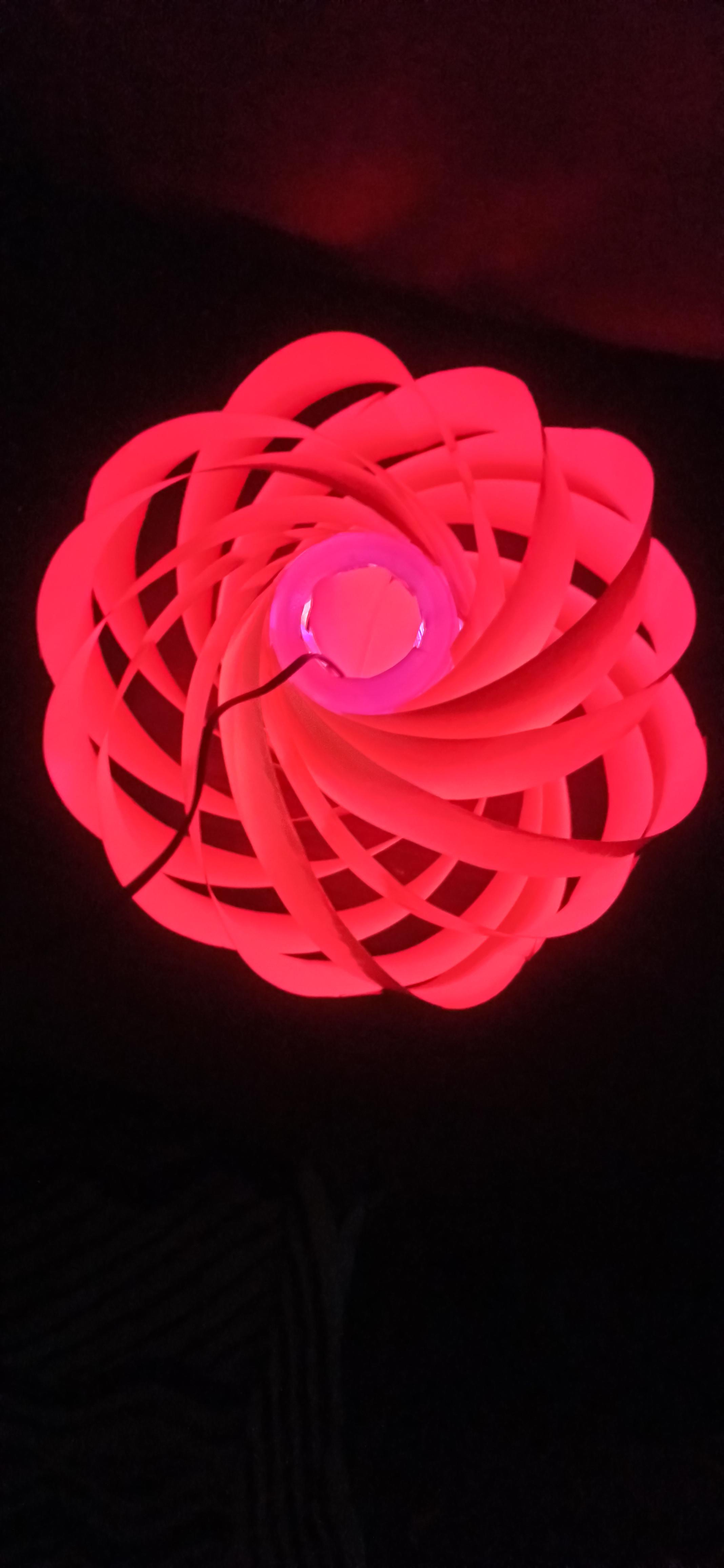
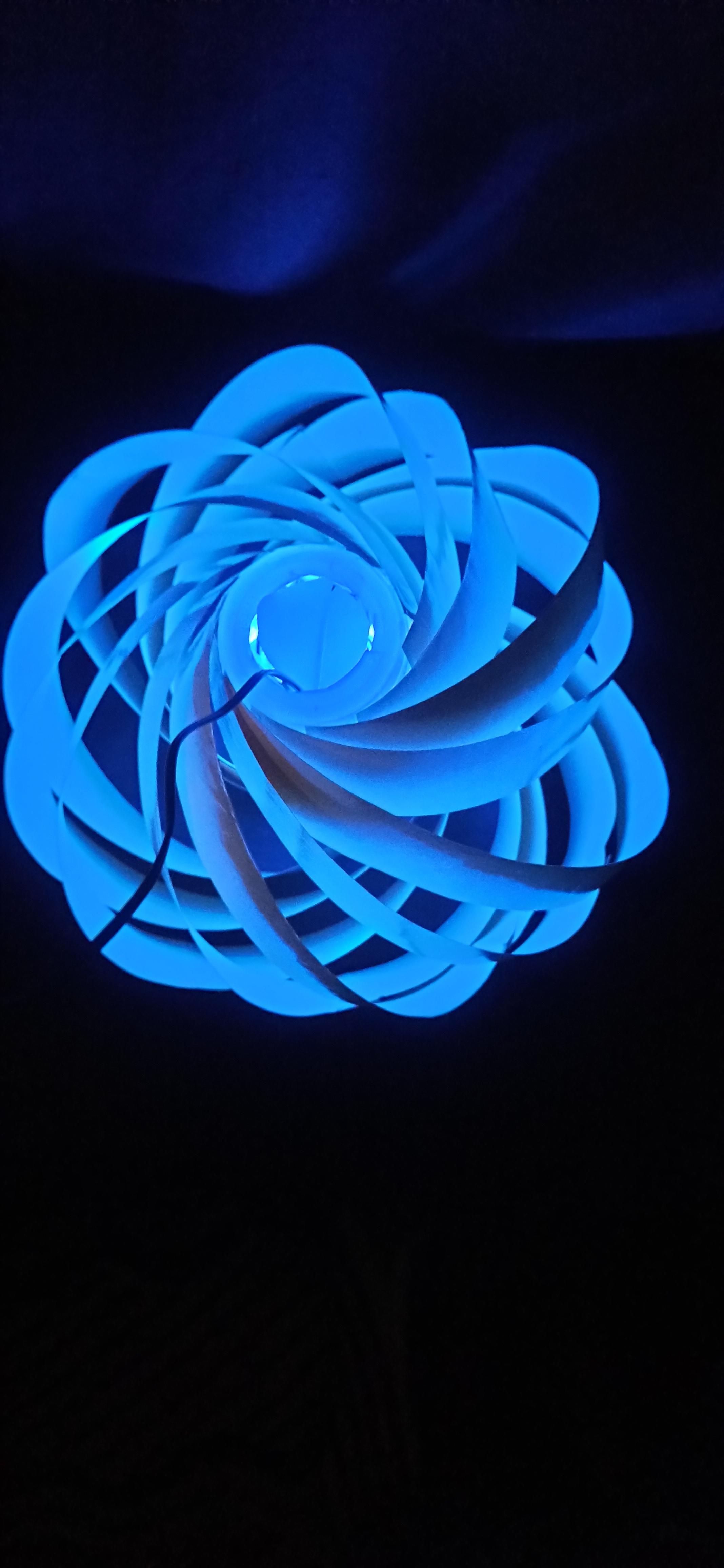
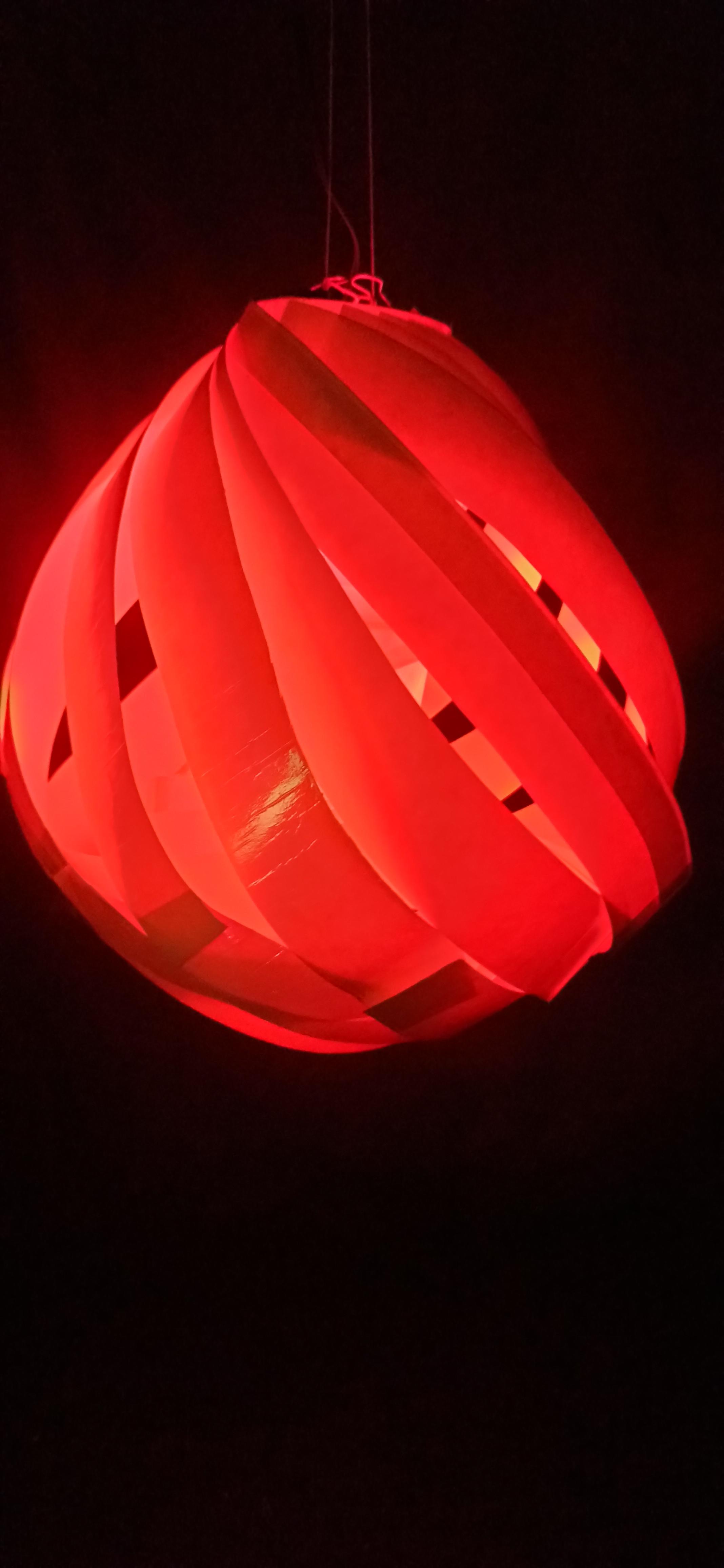
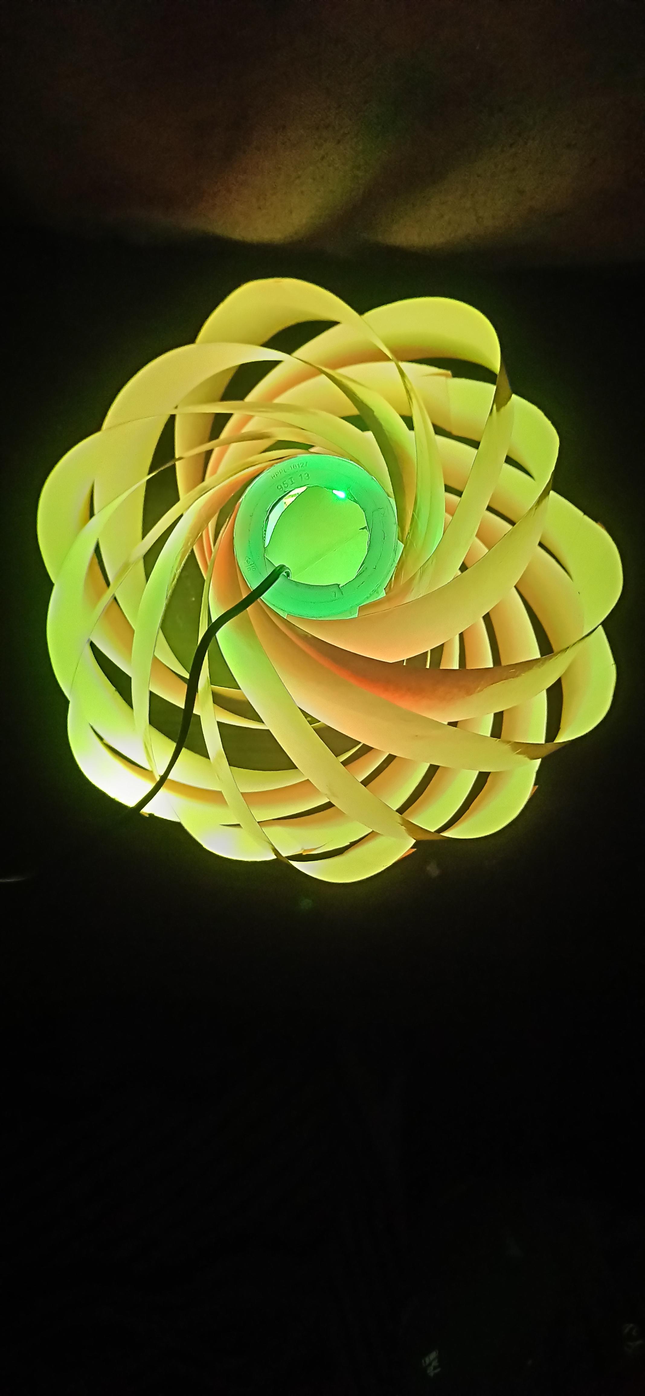
In conclusion, the RGB lamp project using NodeMCU and Blynk allows for customizable and interactive lighting. By using the Blynk app and NodeMCU board, you can control the LED strip from anywhere with internet access. This project highlights the potential of microcontrollers for DIY electronics and IoT projects. With basic electronics knowledge and programming skills, anyone can build their own RGB lamp and explore endless possibilities.