DIY Power Supply
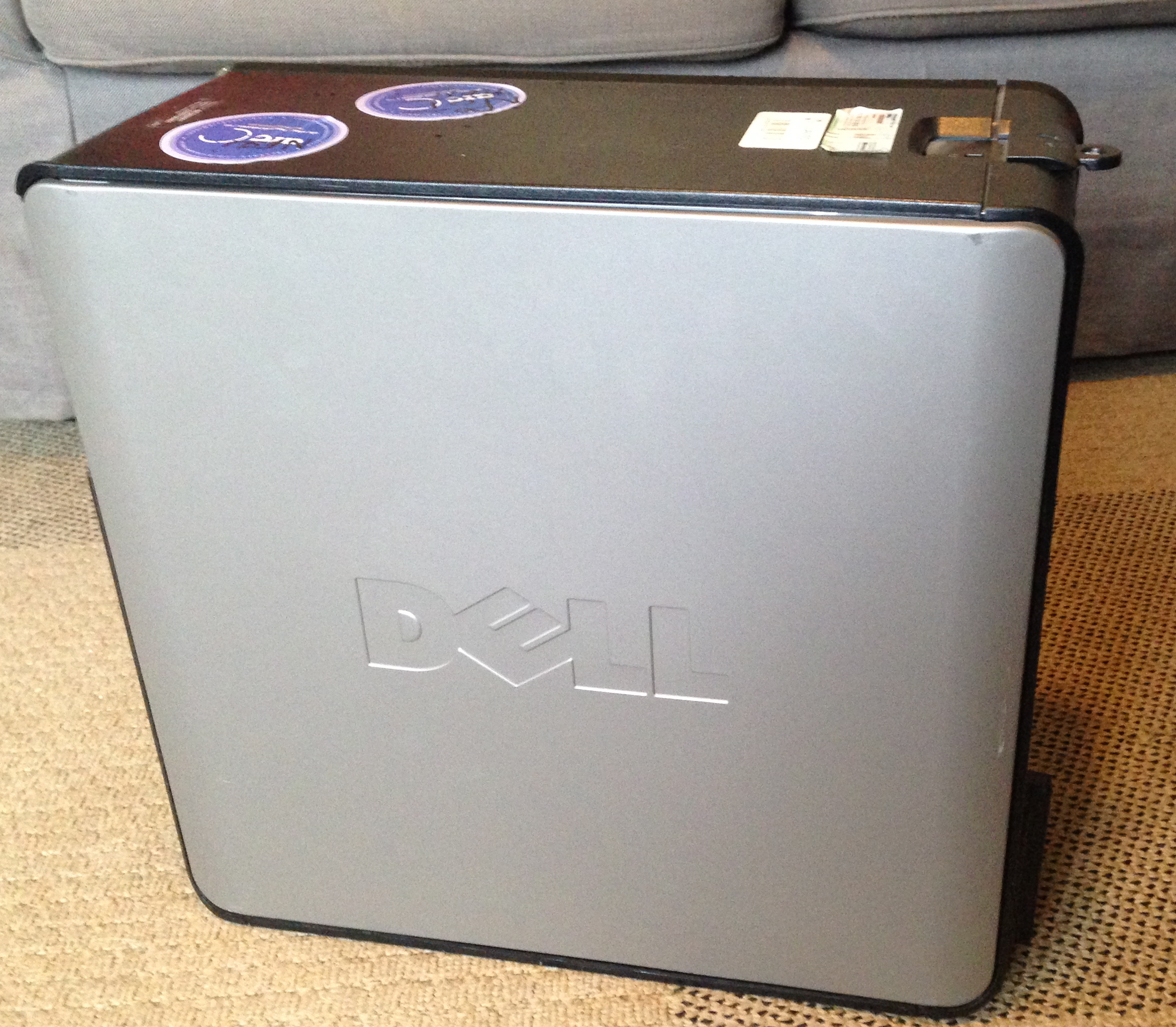
Obtaining a free power supply is incredibly quick and easy with a few basic tools and an old desktop computer. Most desktop computers are perfectly fine when they are exchanged for a newer, top-of-the-line system. If you have no other use for a working desktop, you can harvest the power supply to provide a source of 12V, 5V, and 3.3V DC to test your electrical creations.
Where can you find an old desktop computer? Check w/ local offices, colleges, schools, etc. Nearly every place will have a storage room full of old systems, most will be happy to donate one to your quest. Be sure that any existing data on the computer is wiped or inaccessible.
Materials
-- Desktop computer
Tools
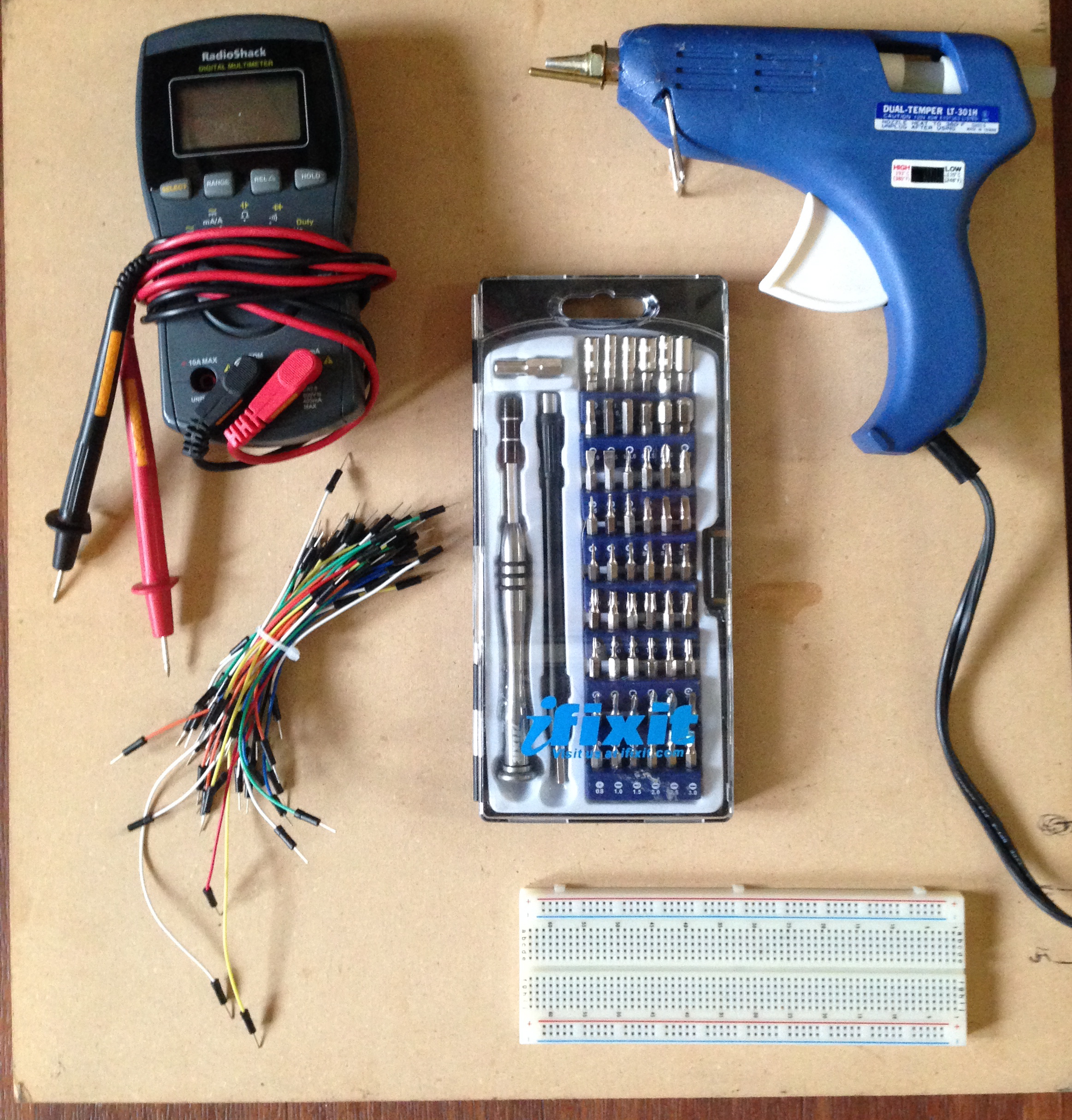
-- Screwdriver set
-- Multimeter
-- Hot Glue Gun
-- Wire
Breadboard wires are perfect, but regular solid core or stranded wire works fine.
-- Optional: Breadboard
Remove Outer Casing.
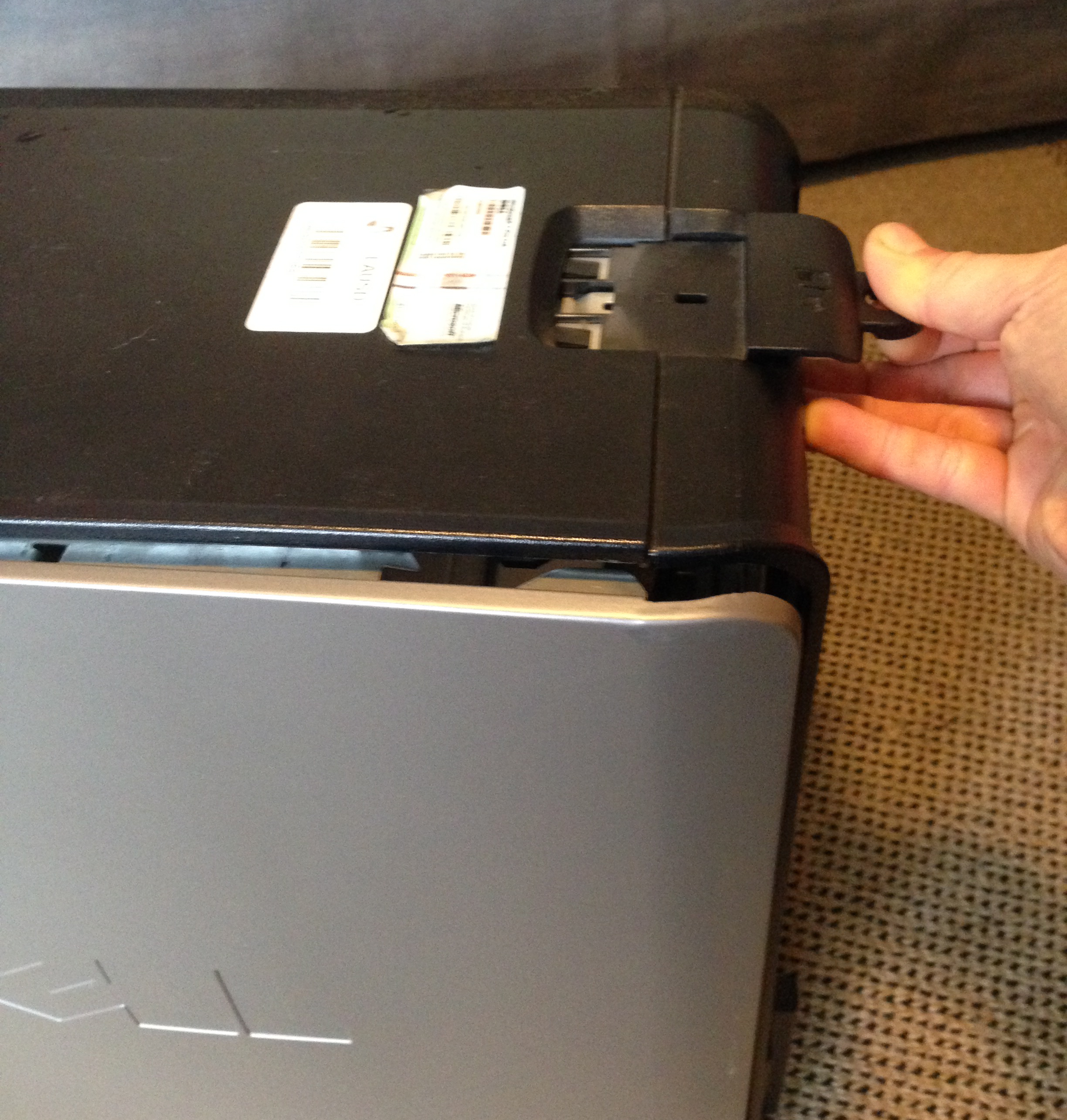
All desktop computers are unique. Examine the case for screws or another opening mechanism. The one I used had a pull-tab that pops open one side.
Preferable to remove the outer casing without damaging it (this should be totally doable).
Remove Power Supply
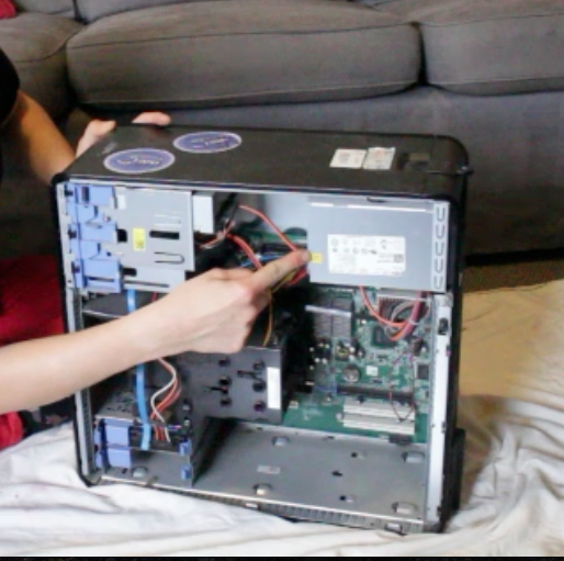
1. Unplug all connected cords.
2. Locate screws for power supply and unscrew.
3. Wiggle it out of the computer.
If it resists, check for hidden screws.
Plug in Power Supply & Test Connections
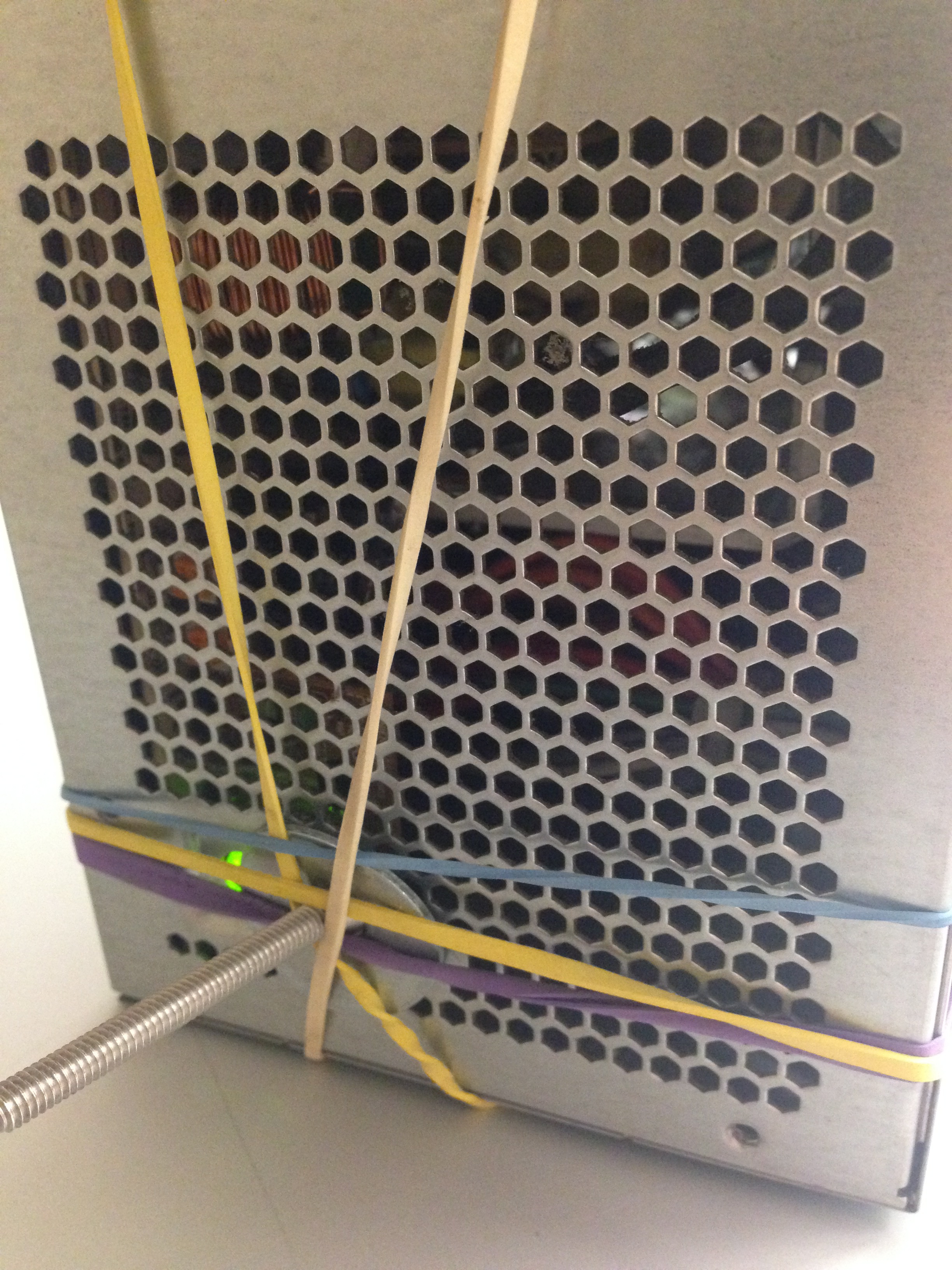
1. Plug power supply in using desktop cable.
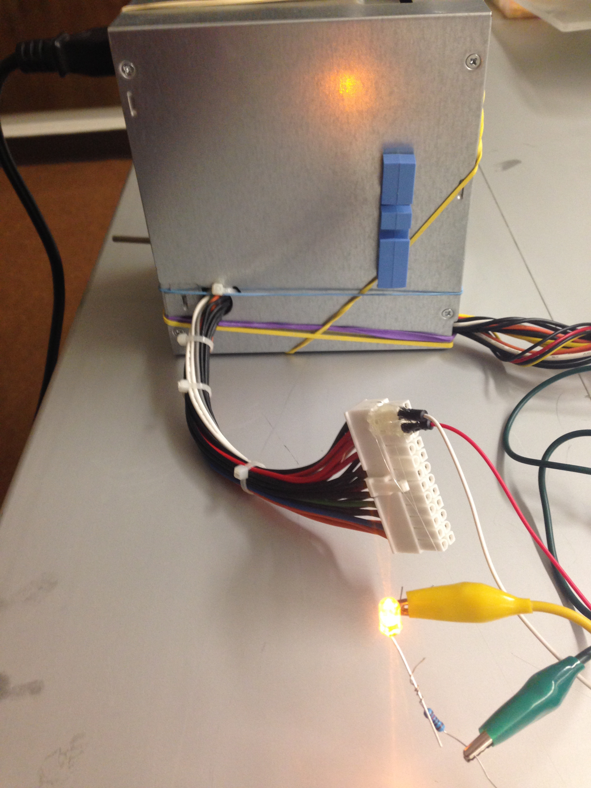
A small light will go on when the power supply is on. You may need to "MacGuyver" a switch to keep it on (see above photo w/ screw + rubber bands.)
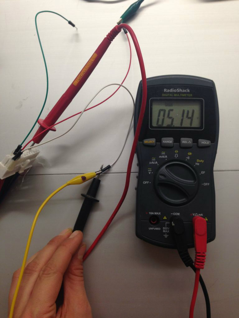
2. Using a multimeter, measure the voltage across the pins of the largest connector.
The color of the wires provides information about each pins' function: black is ground, and red is positive VDC.
There is likely only one ground pin.
3. Find where the voltage is 12 VDC, 5 VDC, and 3.3 VDC. Mark these pins and the ground pin on the connector.
There is one pin that supplies +12 VDC, and a few that supply 5 VDC and 3.3 VDC.
Connect Wires & Test.
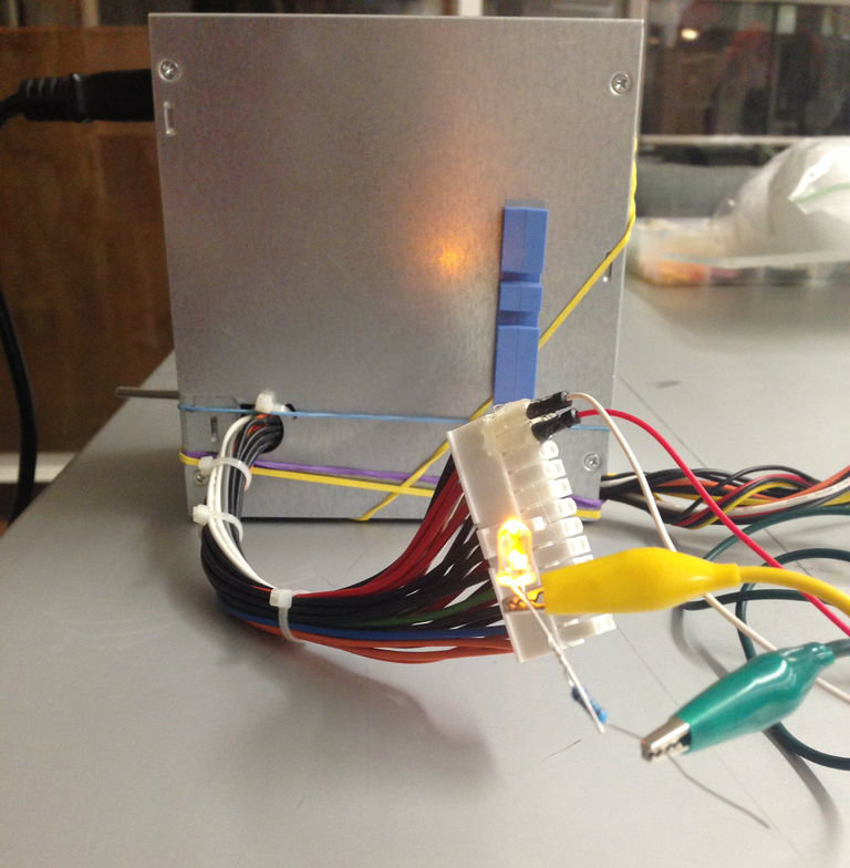
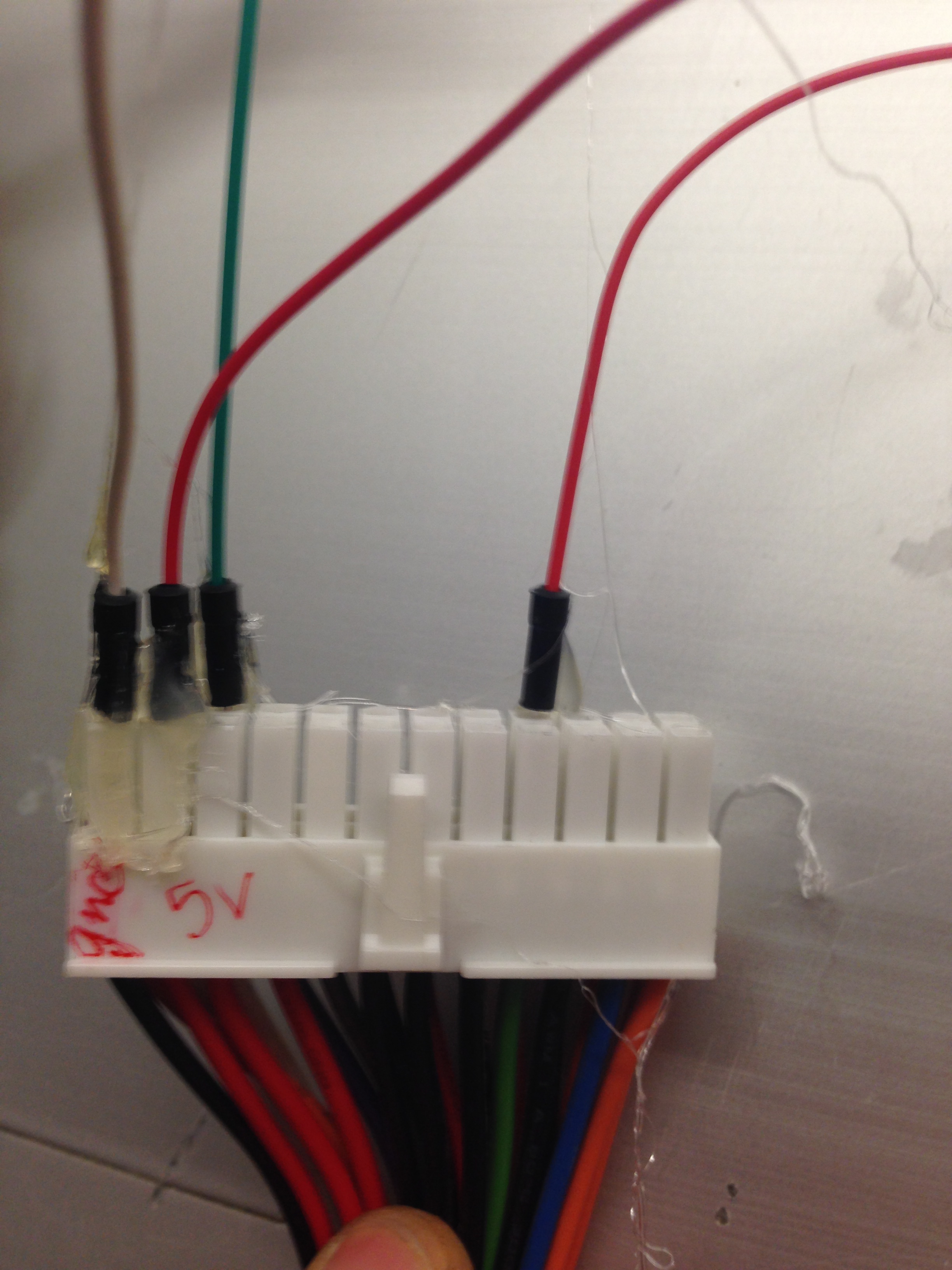
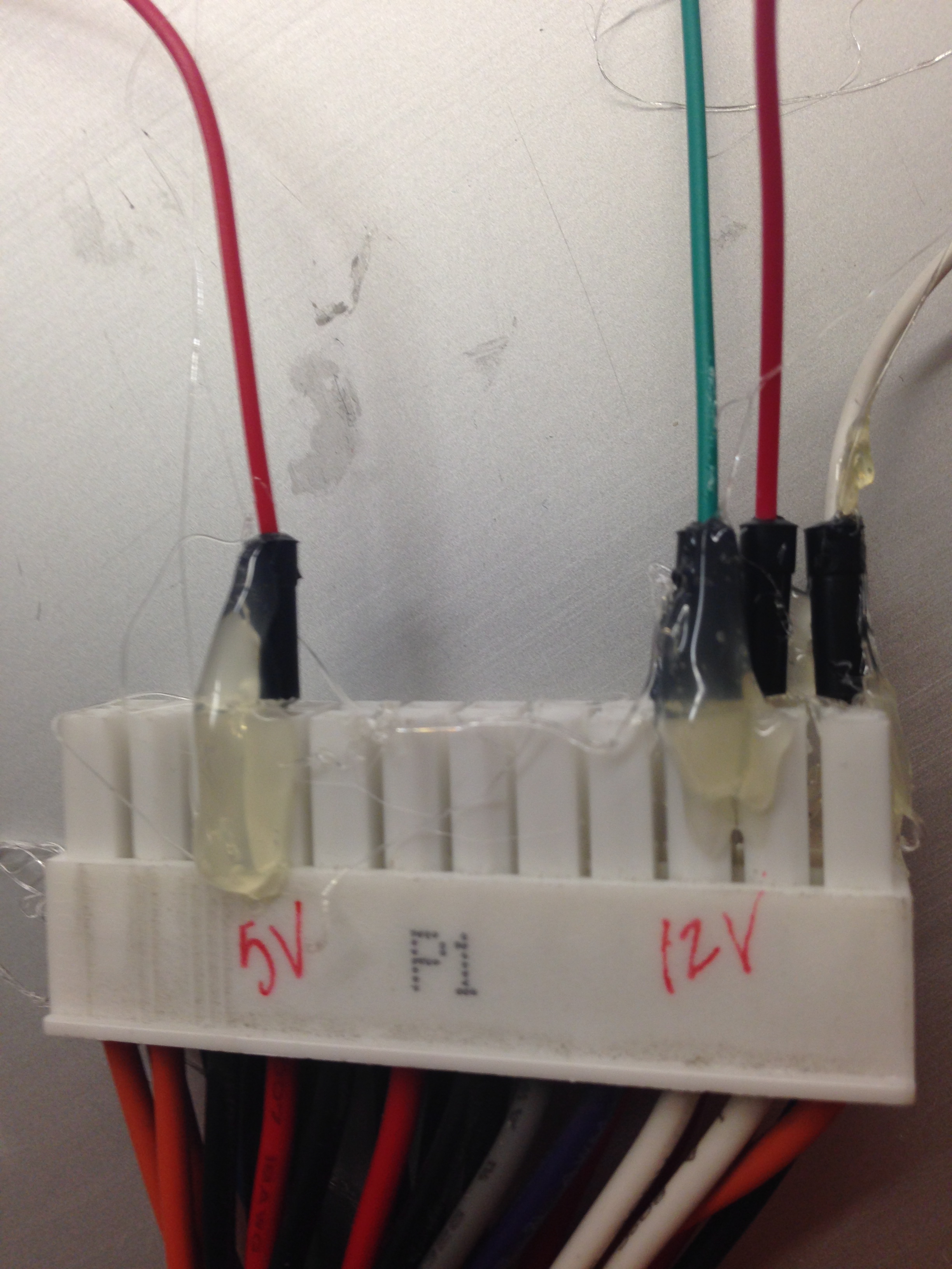
1. Plug in a connector or individual wires to the pins marked ground, 12 VDC, 5 VDC and 3.3 VDC.
Recommended to attach wires with some adhesive like hot glue.
2. Check connections w/ a simple circuit like an LED (+ resistor).
Check that the power supply lights up an LED w/ the 3.3 VDC (or 5VDC) wires.
3. Use for testing all the circuits!
Or at least the ones that work w/ 3.3, 5, and 12 VDC.. which are about what you'll need for hobbyist electronic projects so it's perfect!