DIY Multifunction Energy Meter V2.0
by opengreenenergy in Circuits > Arduino
14063 Views, 83 Favorites, 0 Comments
DIY Multifunction Energy Meter V2.0
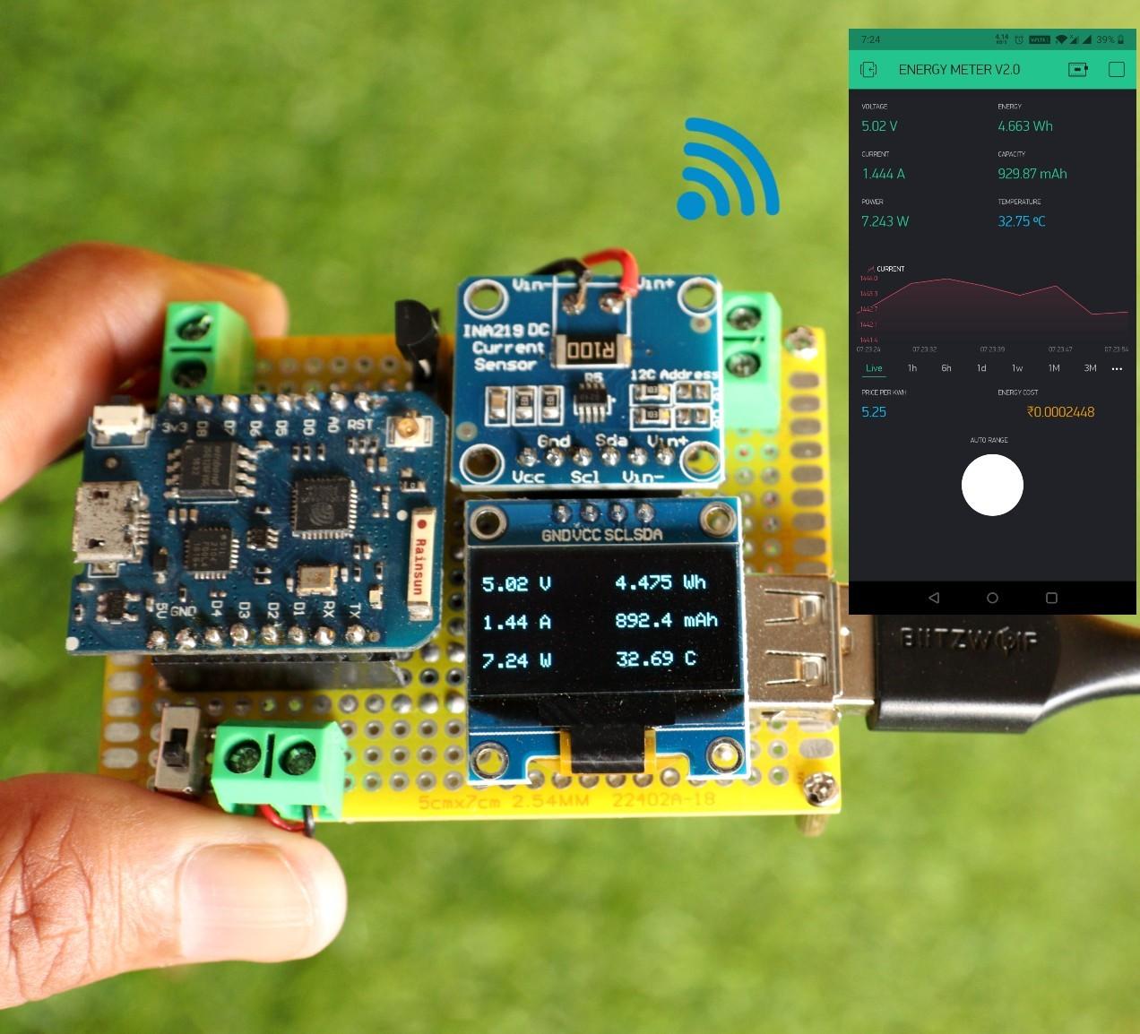
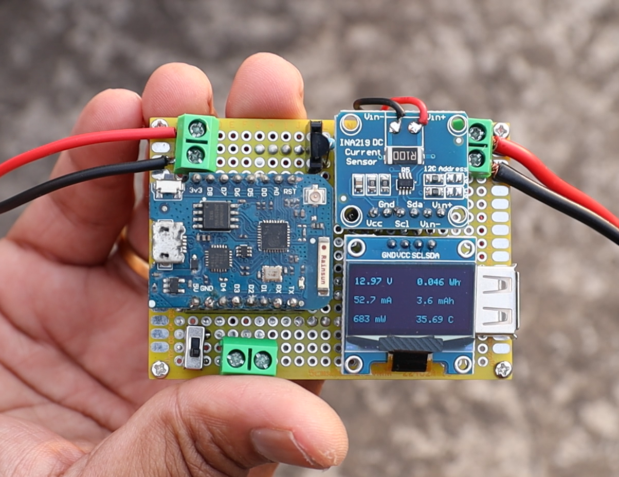
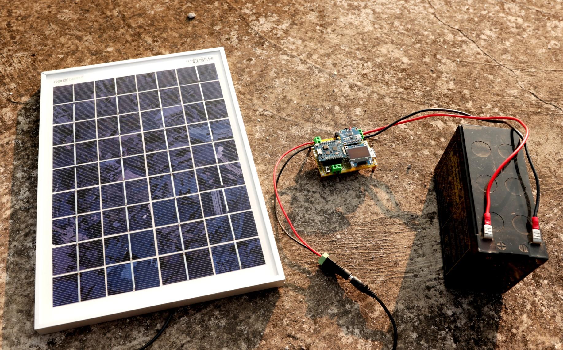

In this Instructable, I will show you how to make a Wemos ( ESP8266 ) based Multifunction Energy Meter. This little Meter is a very useful device that monitors voltage, current, power, energy, and capacity. Apart from these it also monitors the ambient temperature which is important for solar photovoltaic application. This device is suitable for almost any DC device. This small meter can also be used for measuring the real capacity of the battery pack or power bank using a dummy load. The Meter can measure up to voltage range from 0 - 26V and a maximum current of 3.2A.
This project is a continuation of my earlier Energy meter project.
The following are the new features added to the earlier version
1. Monitor the parameters from the smartphone
2. Auto range of parameters
3. Monitoring the Electricity Bill
4. USB device tester
I got inspired by the following two projects
1. Power Monitor” - DC Current and Voltage Sensor (INA219)
2. Make Your Own Power Meter/Logger
I would like to give special thanks to the above two project authors.
My Book : DIY Off-Grid Solar Power for Everyone
You can order my Book on Off-Grid Solar Power from Amazon
Support me On Patreon:
If you enjoy my work here on Instructables, consider joining my Patreon, it will be a great help for me to make more interesting projects in the future.
Patreon Link: https://www.patreon.com/opengreenenergy
Supplies
Components Used:
1. Wemos D1 Mini Pro ( Amazon )
2. INA219 ( Amazon )
3. 0.96" OLED Display ( Amazon )
4. DS18B20 Temp Sensor ( Amazon )
5. Lipo Battery ( Amazon )
6. Screw Terminals ( Amazon )
7. Female / Male Headers ( Amazon )
8. Perforated Board ( Amazon )
9. 24 AWG Wire ( Amazon )
10. Slide Switch ( Amazon )
11. USB Male Port ( Amazon )
12. 11. USB Female Port ( Amazon )
12. PCB Standoffs ( Amazon )
13. Solar Panels ( Voltaic )
Tools & Instruments Used:
1. Soldering Iron ( Amazon )
2. Wire Stripper ( Amazon )
3. Multimeter ( Amazon )
Step 1: How It Works?
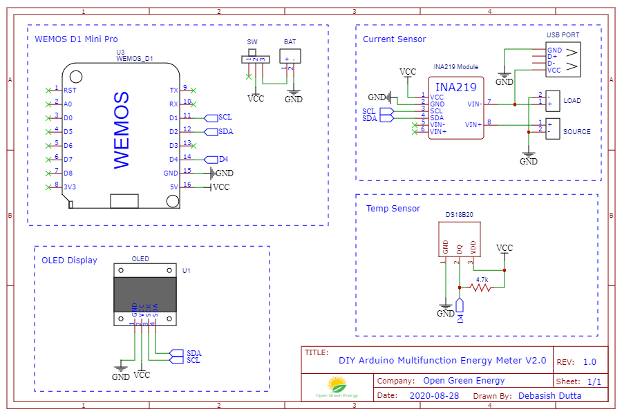
The heart of the Energy Meter is an ESP8266 based Wemos board. The ESP8266 senses the current and voltage by using the INA219 current sensor and temperature by temperature sensor DS18B20. According to this voltage and current, ESP does the maths for calculating power, energy, and capacity. From energy consumption, the electricity bill is calculated based on the energy rate ( price per kWh ).
The Whole Schematic is divided into 4 groups
1. Wemos D1 Mini Pro
The power required for the Wemos board is supplied from a LiPovBattery through a slide switch.
2. Current Sensor
The Current Sensor INA219 is connected to the Arduino board in I2C communication mode ( SDA and SCL pin).
3. OLED Display
Similar to the current Sensor, the OLED display is also connected to the Arduino board in the I2C communication mode. However, the address for both the device is different.
4. Temperature Sensor
Here I have used the DS18B20 temperature sensor. It uses a one-wire protocol to communicate with the Arduino.
Prepare the Header Pins
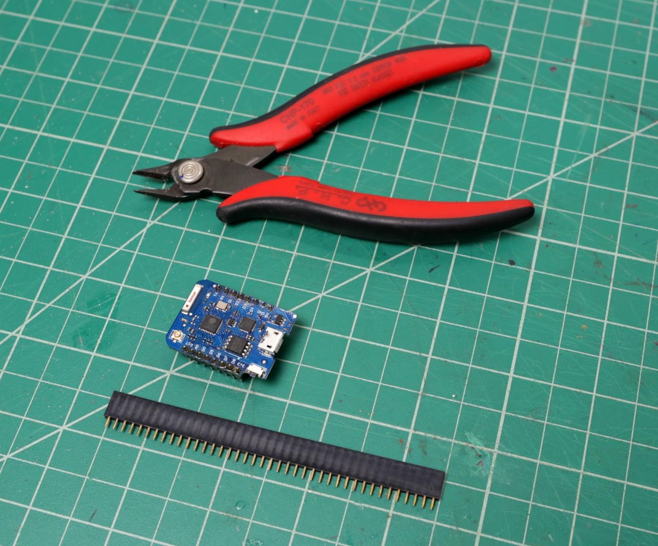
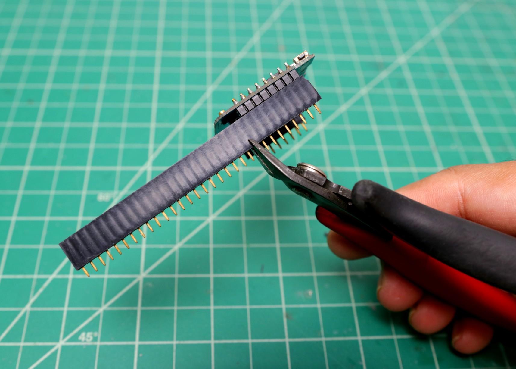
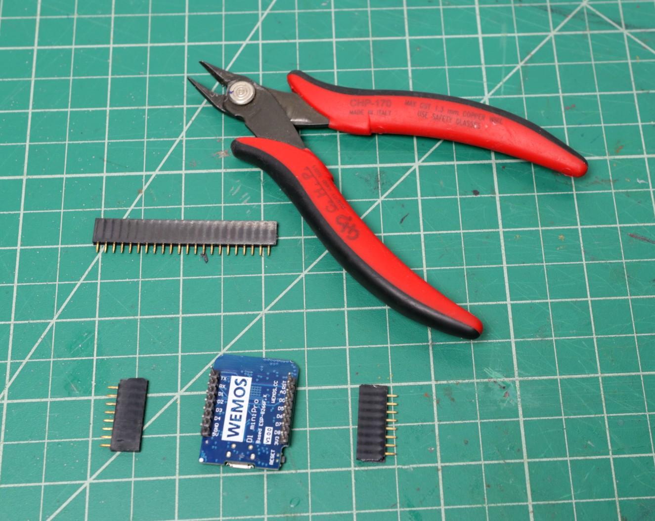
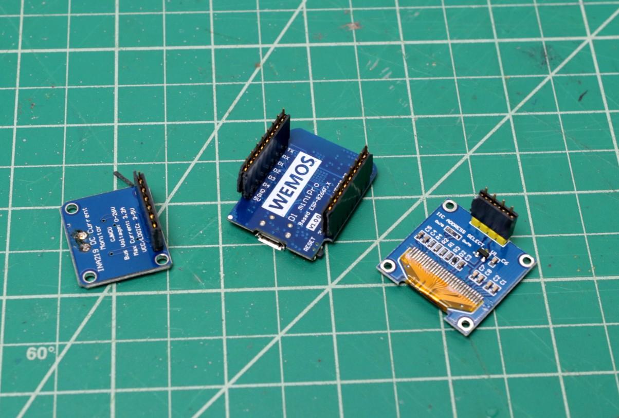
To mount the Arduino, OLED display, current sensor, and temperature sensor, you need some female straight headers pin. When you purchase the straight headers, they'll be too long for the components to be used. So, You'll need to trim them down to an appropriate length. I used a nipper to trim down it.
The following are the details about the headers :
1. Wemos Board - 2 x 8 pins
2. INA219 - 1 x 6 pins
3. OLED - 1 x 4 pins
4. Temp. Sensor - 1 x 3 pins
Solder the Female Headers
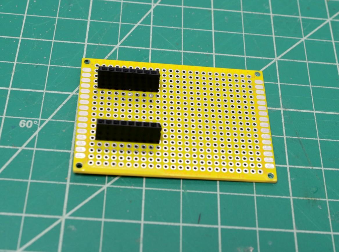
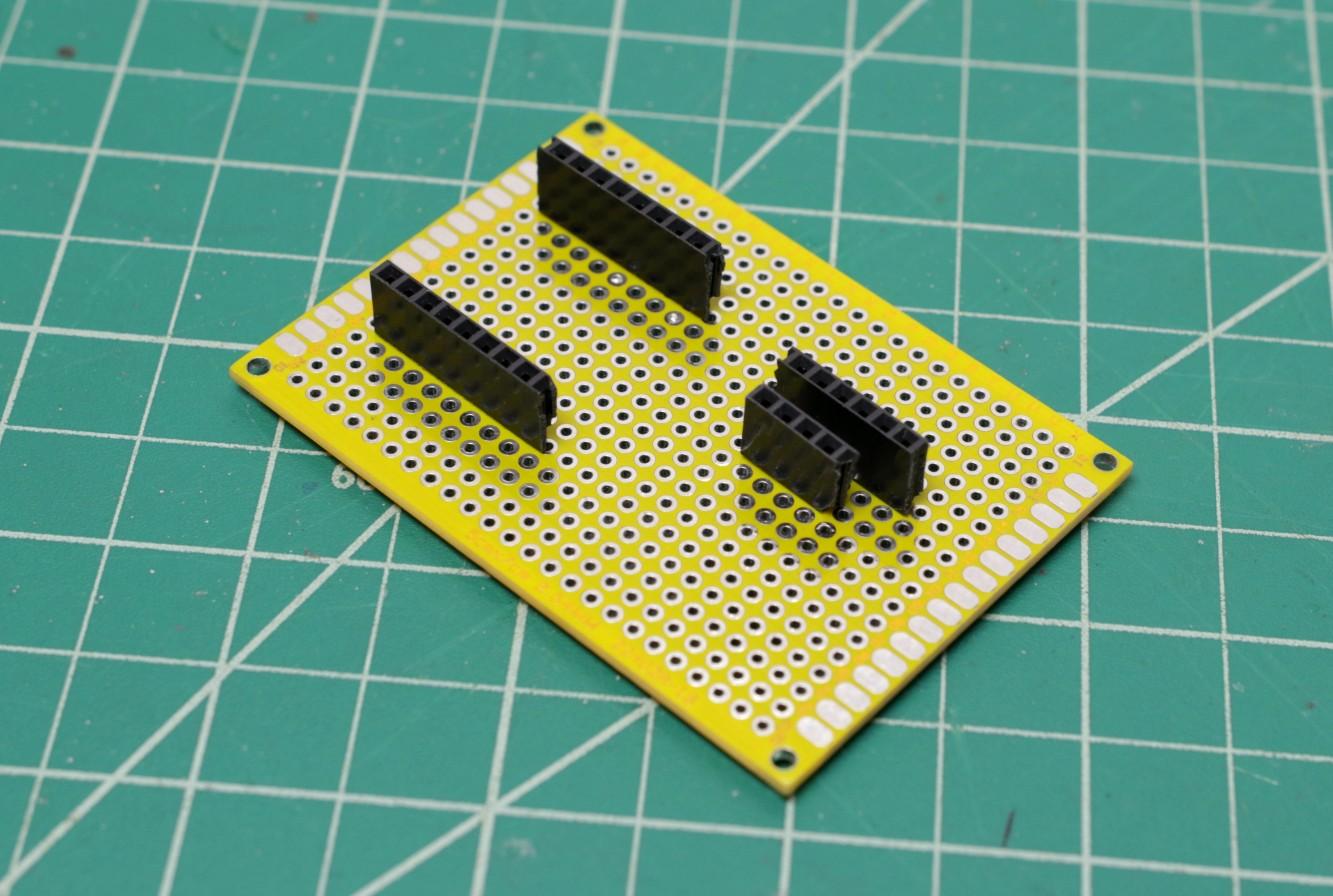
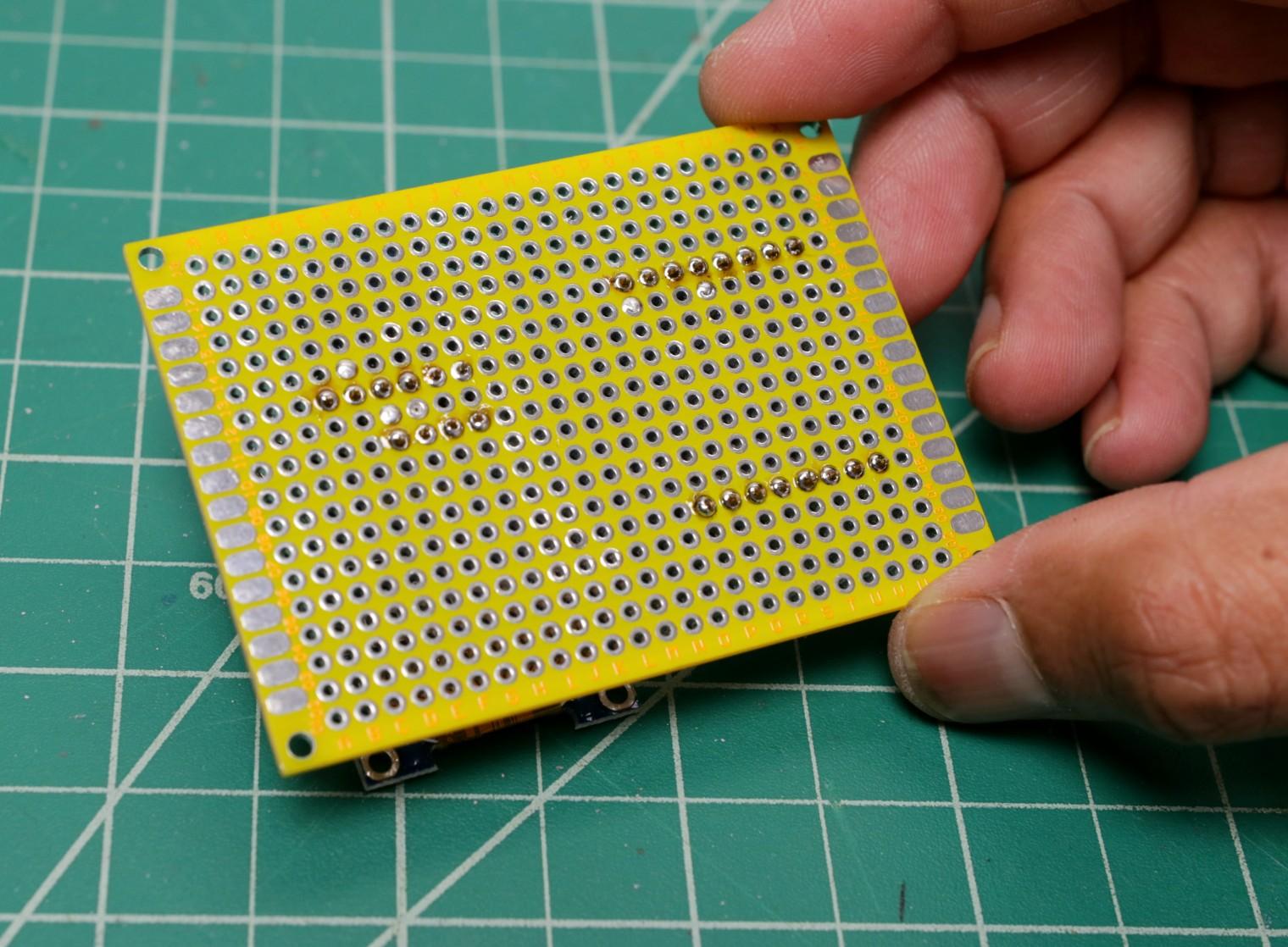
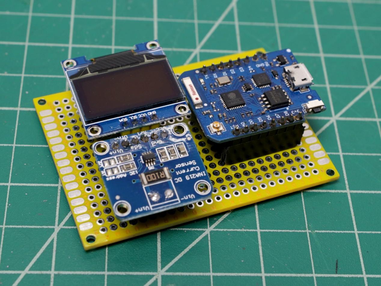
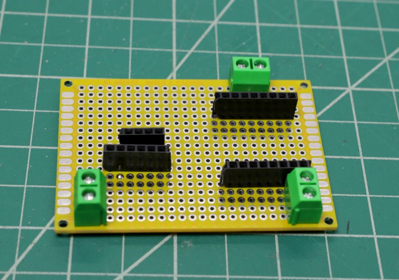
After preparing the female headers pin, solder them to the perforated board.
After soldering the header pins, check whether all the components fit perfectly or not.
Solder Screw Terminals, USB Port and Switch
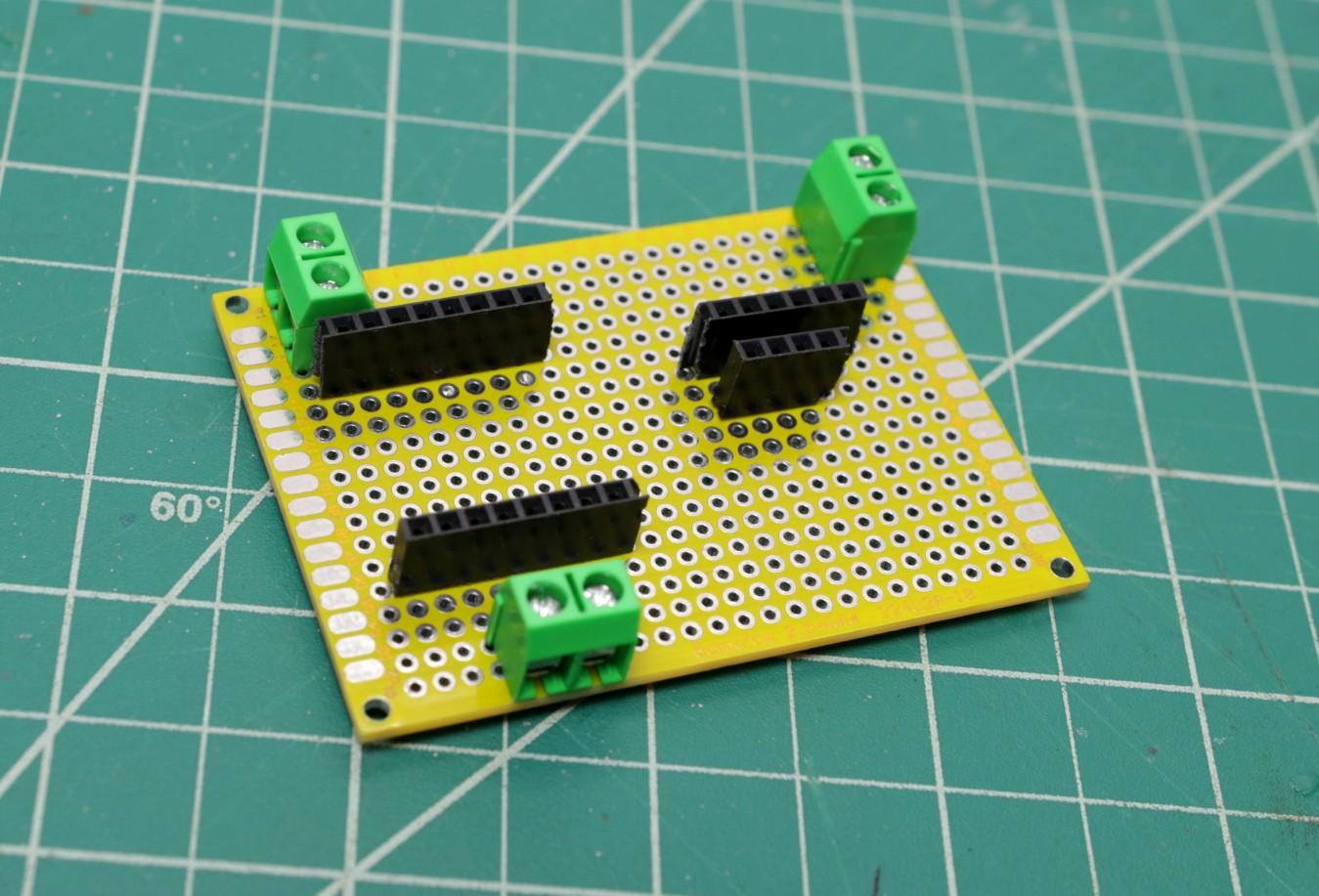
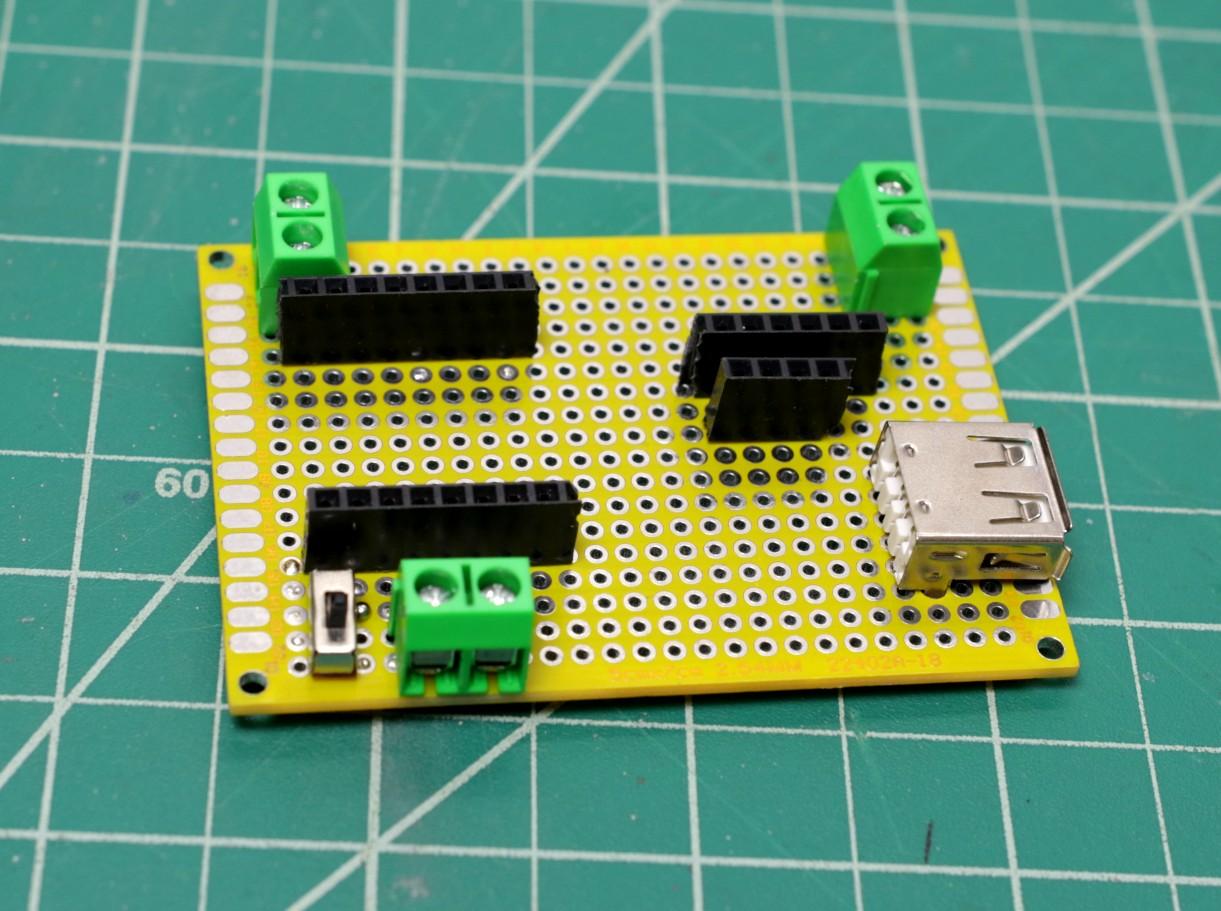
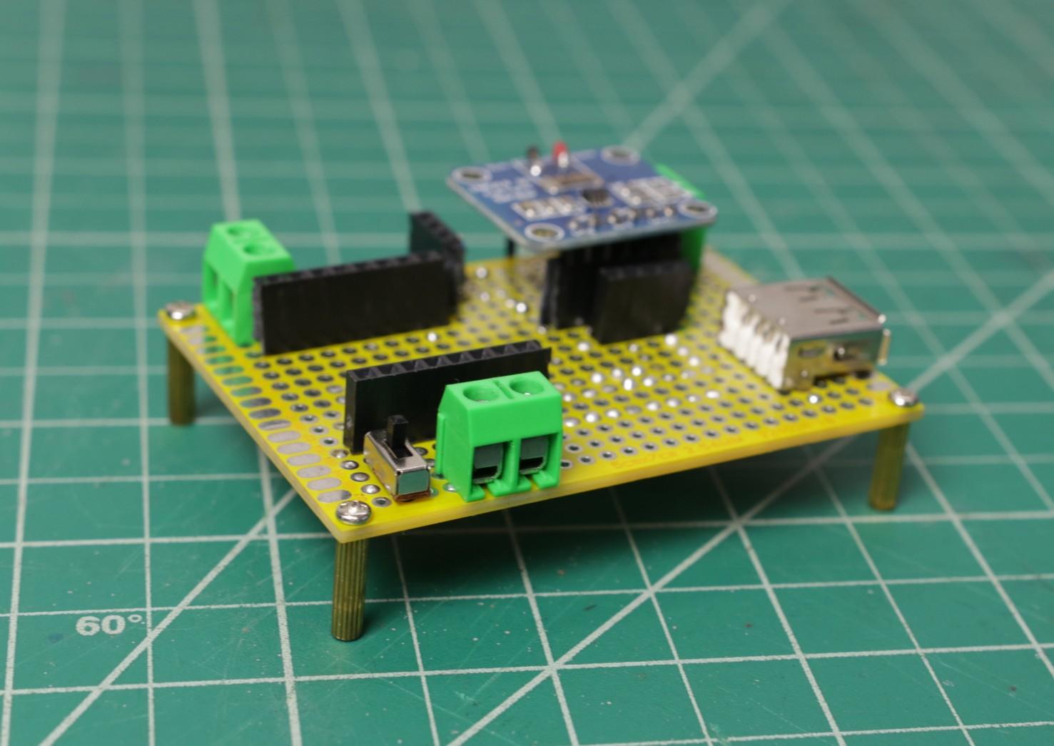
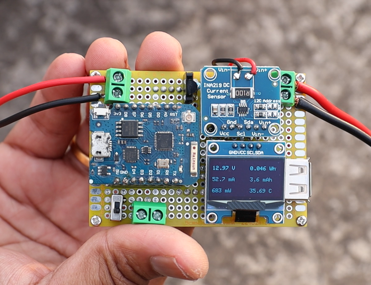
First solder the 3 screw terminals, the screw terminals are used for connecting 1. Source 2. Load and 3. Battery
The top terminals are used for source and load connection and the bottom terminal placed side to the switch is used for connecting the battery pack.
Then solder the slide switch. The slide switch turns ON and OFF power to the Wemos board.
At last solder the female USB port. The size of the mounting legs of the USB port is slightly larger than the holes in the perforated hole, so you have to make the hole wider by using a drill. Then press the USB port into that holes and solder all the pins.
Prepare the INA219 Sensor
.png)
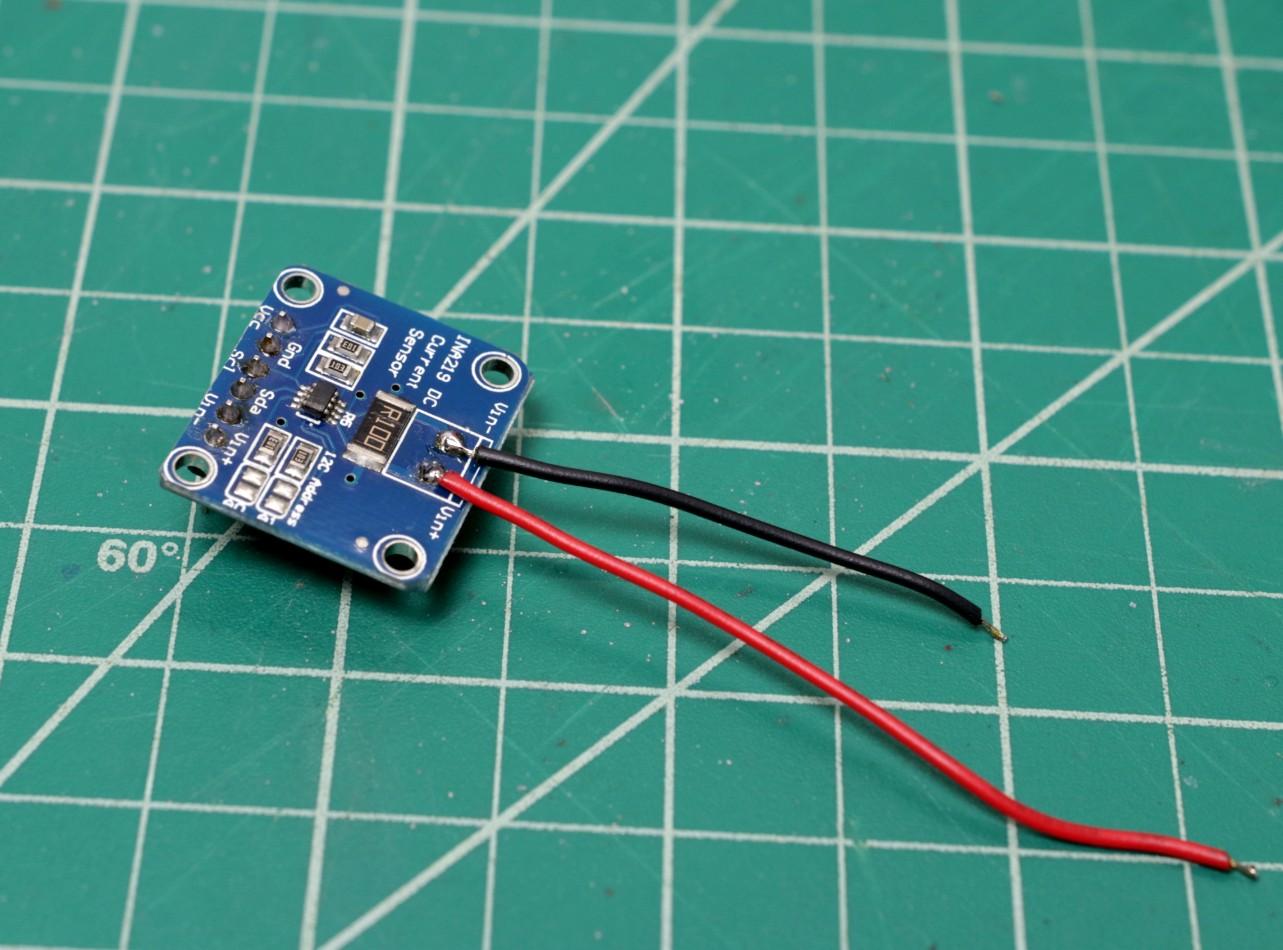
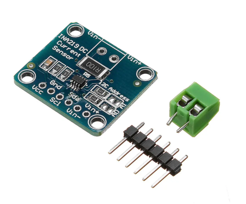
The INA219 sensor comes with 6pin male header strips and a screw terminal. The male header pins are for I2C connection with microcontroller and the screw terminal is for power line connection for measuring the current.
Here I have soldered the 6pin male pins to the INA219 and left the screw terminal for considering aesthetic look. Then I directly solder two wires to the soldering pad given for the screw terminal as shown in the above picture.
Mount the Temperature Sensor
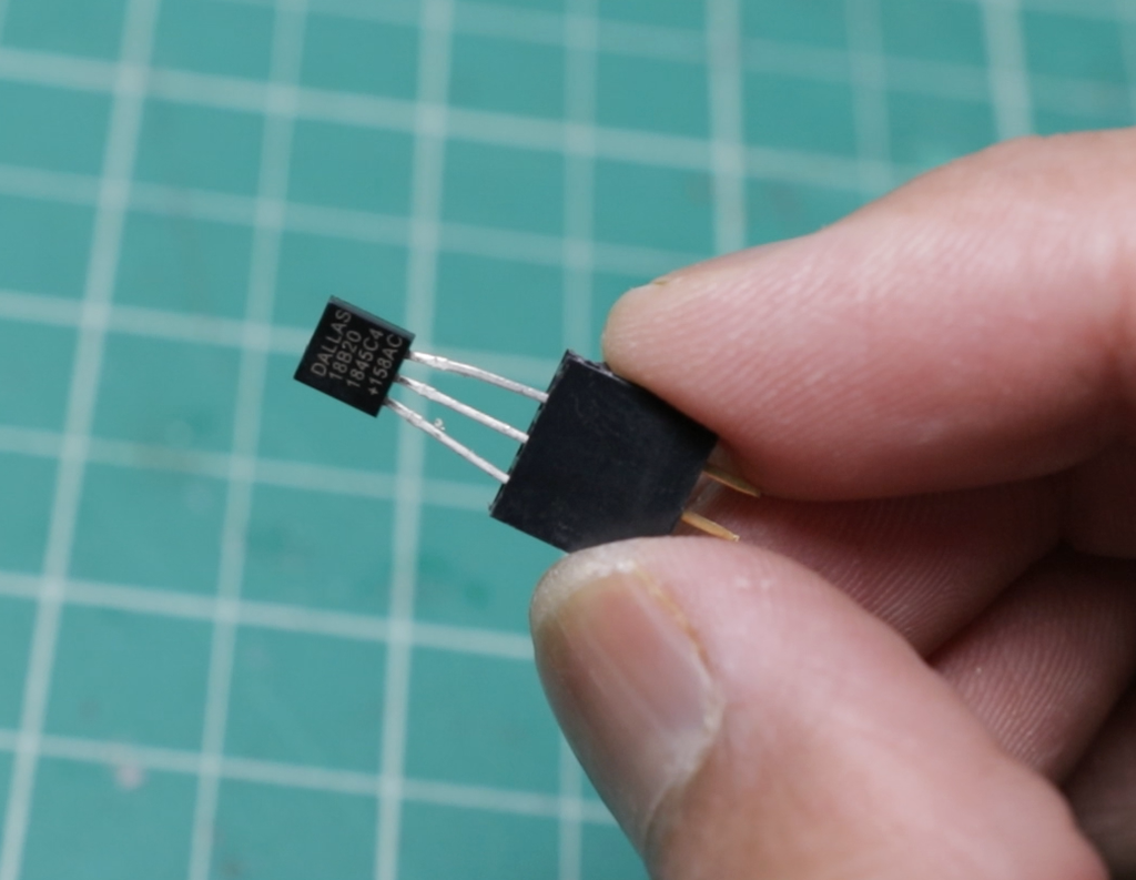
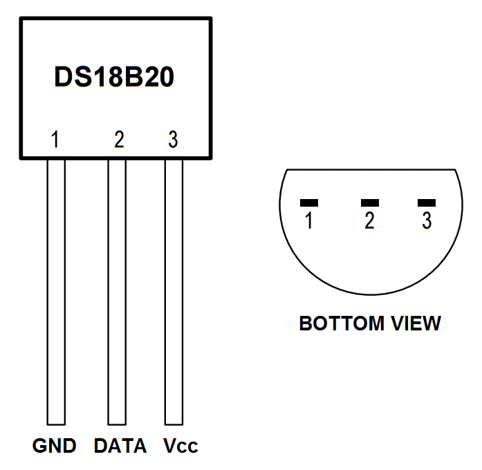
Here I am using the DS18B20 temperature sensor in the TO-92 package. By considering the easy replacement, I have used a 3 pin female header. But you can directly solder the sensor to the perforated board.
The pin diagram for DS18B20 is shown in the above picture.
Make the Circuit
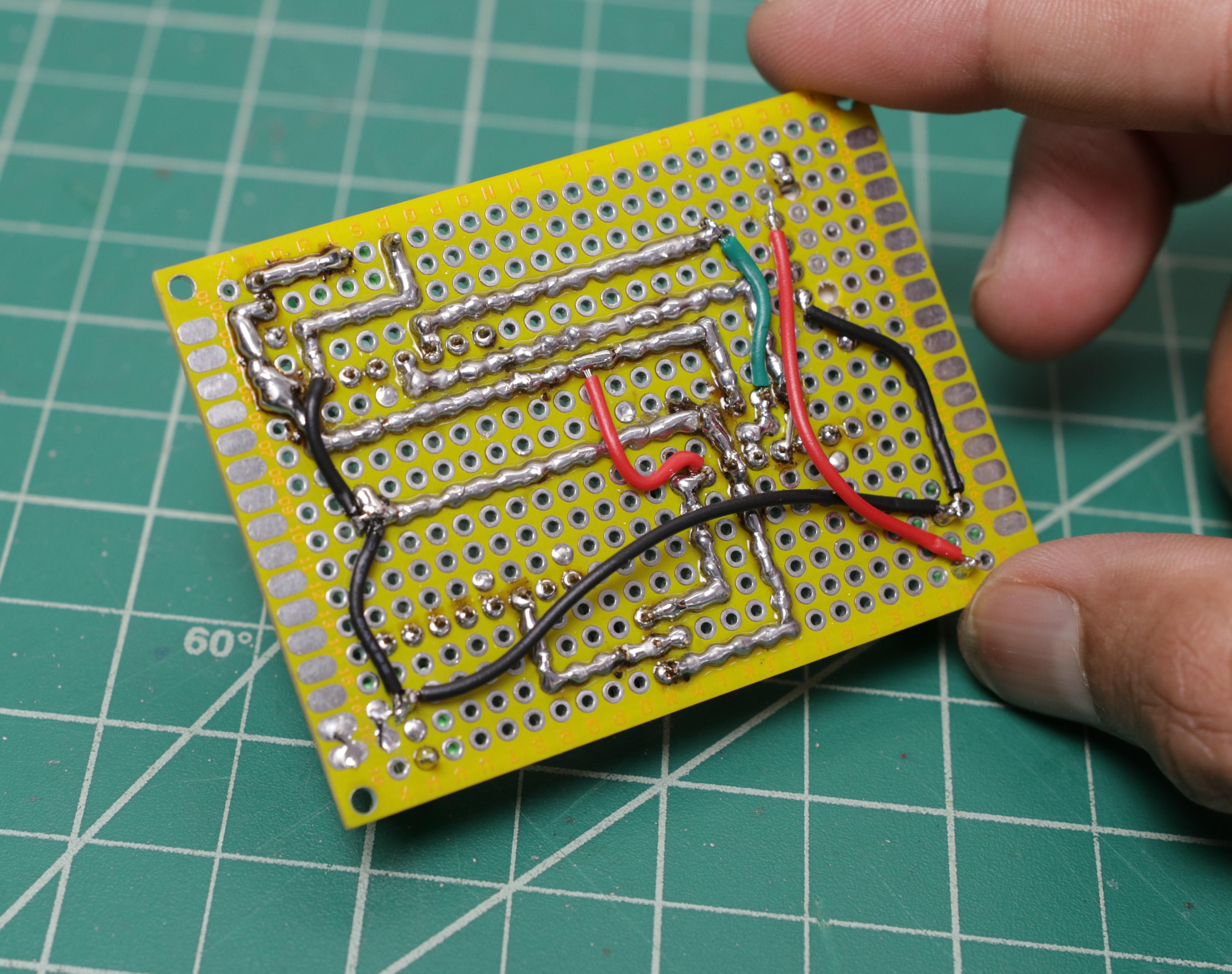
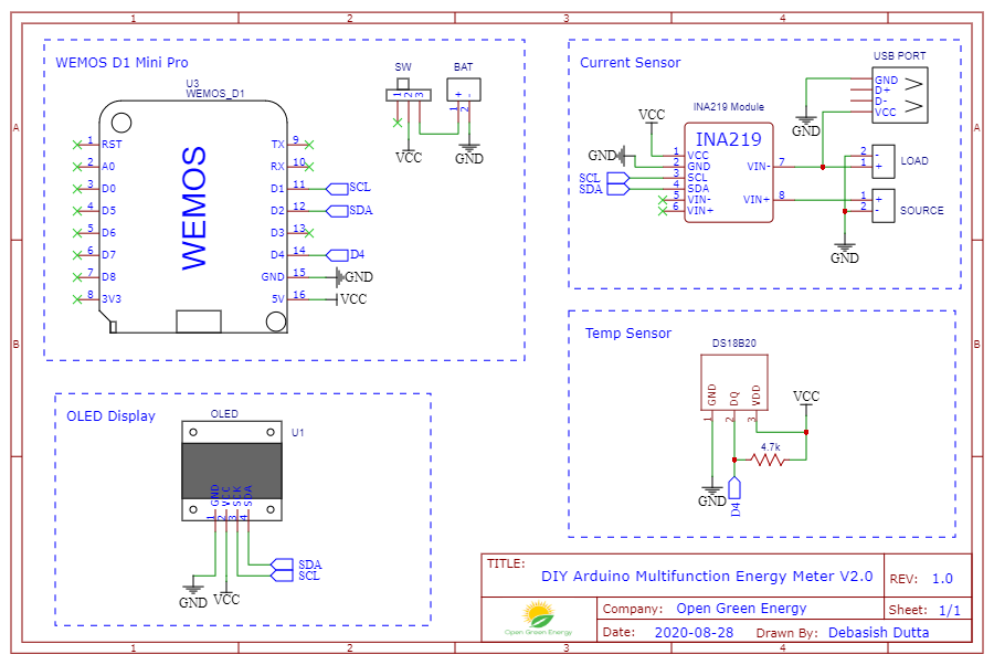
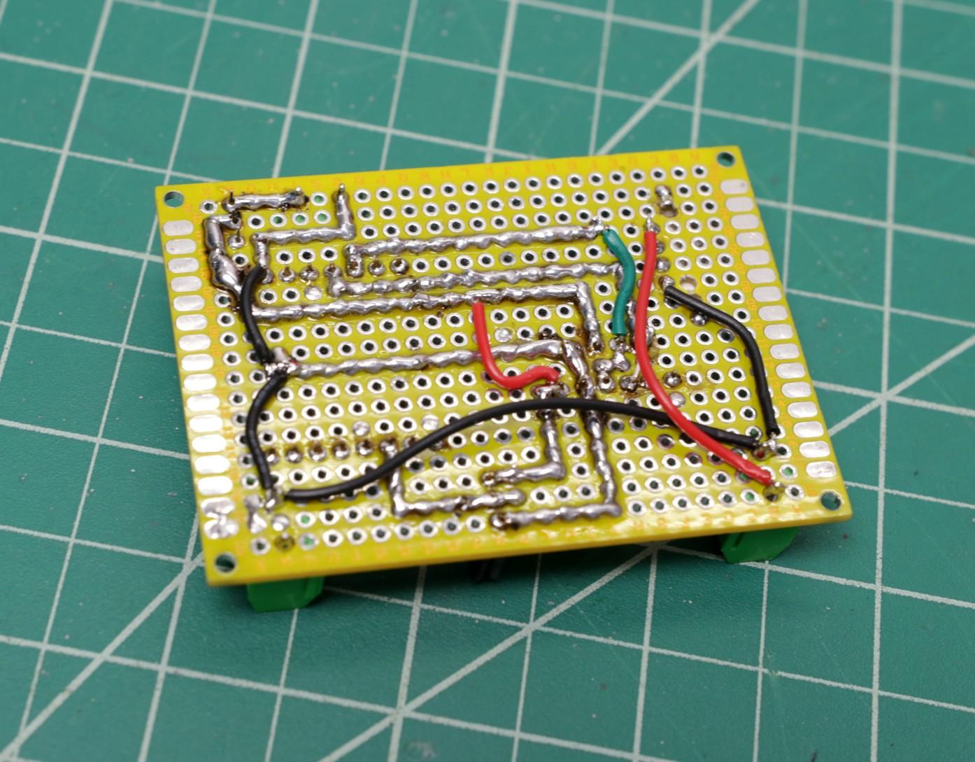
After soldering the female headers and screw terminals, you have to join the pads as per the schematic diagram shown above.
The connections are pretty straight forward
INA219 / OLED -> Wemos
VCC -> VCC
GND - > GND
SDA -> D2
SCL-> D1
DS18B20 -> Wemos
GND - > GND
DQ -> D4 through a 4.7K pull-up resistor
VCC -> VCC
At last, connect the screw terminals as per the schematic.
I have used 24AWG colored wires to make the circuit. Solder the wire as per the circuit diagram.
Prepare the Battery Pack
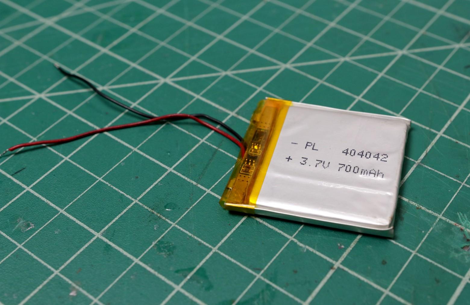
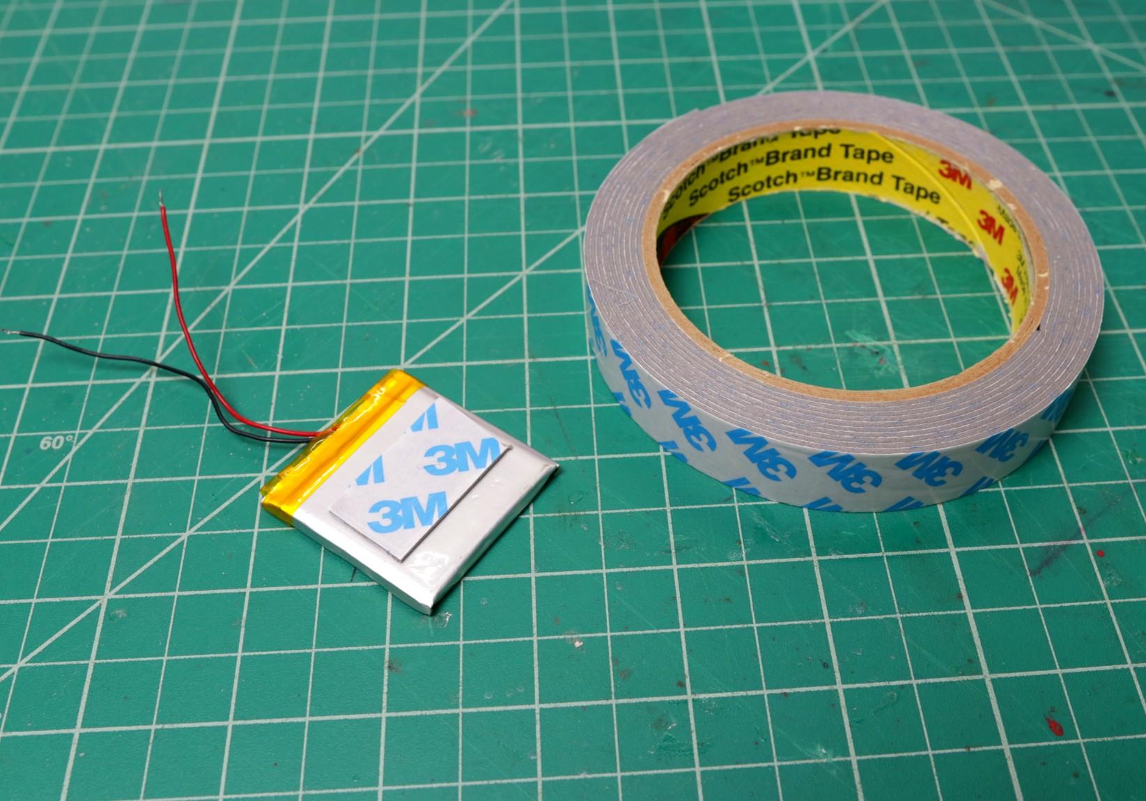
Here I have used a 700mAh battery pack to power the Wemos board. The battery pack is mounted on the backside of the circuit board. To mount the battery, I have used 3M double-sided tape.
Few thoughts :
1. If you don't want to use a battery pack, you can use source power to power the Wemos board by using a voltage regulator circuit.
2. You can add a TP4056 charging board to charge the LiPo battery.
Mounting the Standoffs
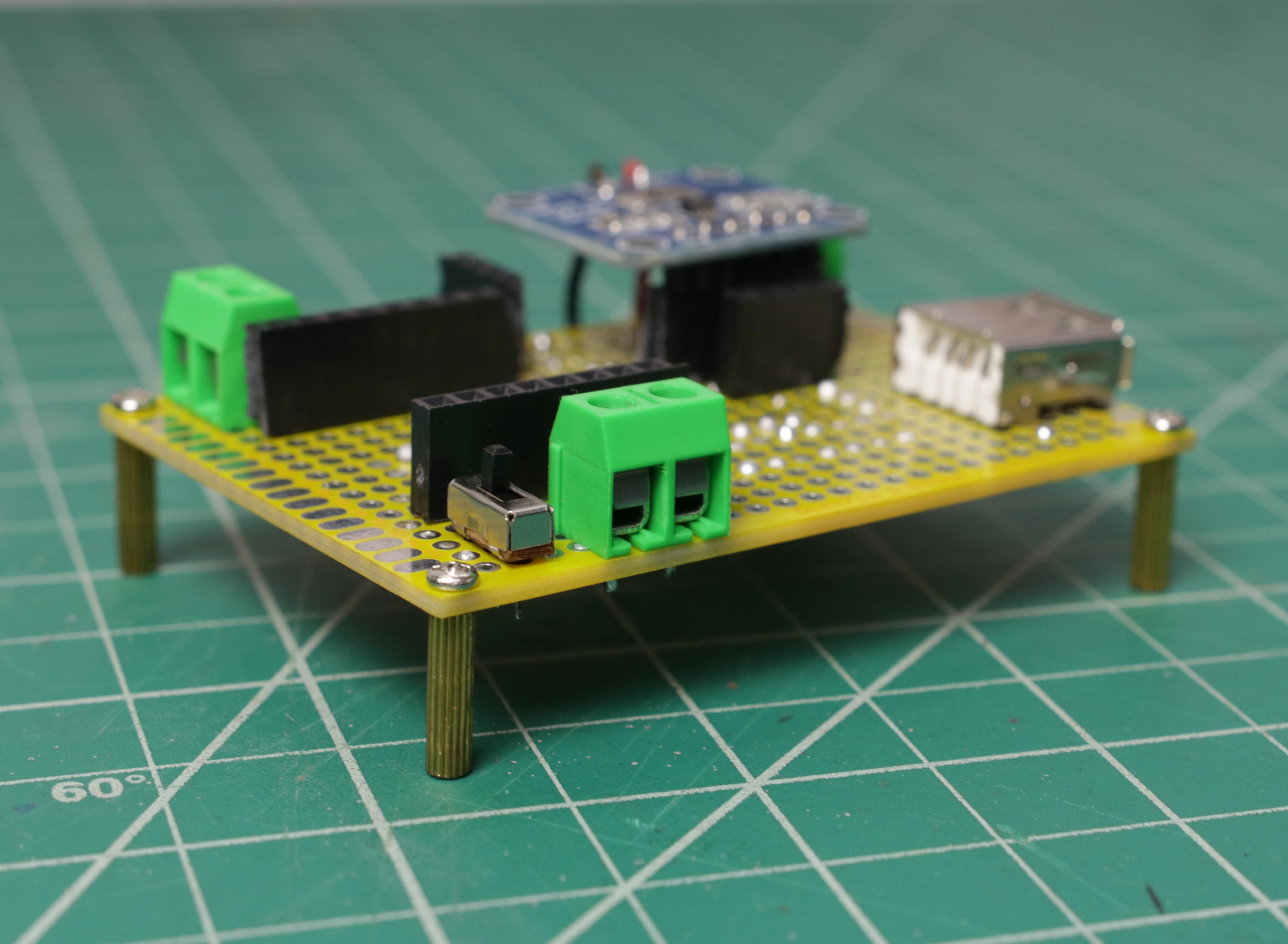
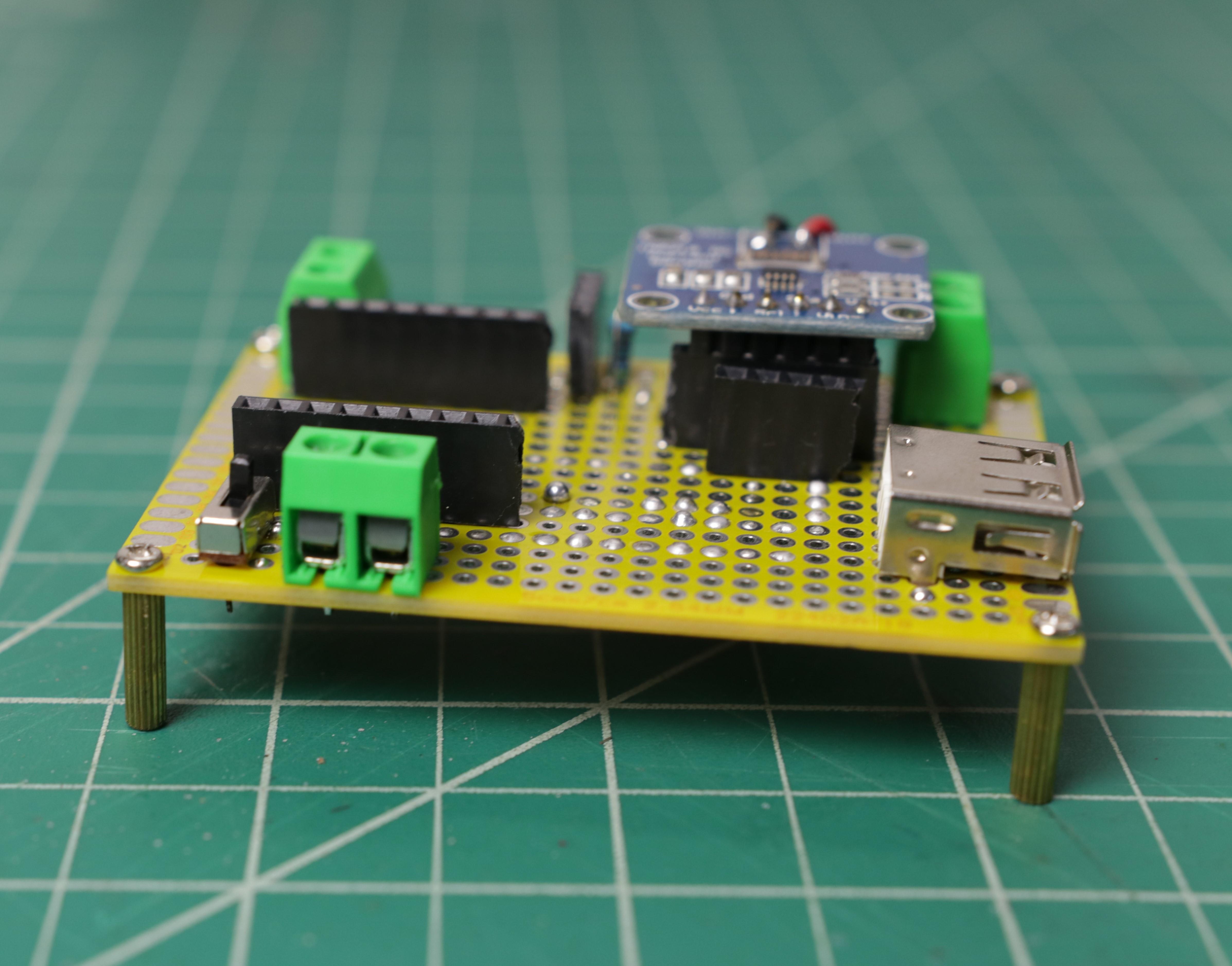
After soldering and wiring, mount the standoffs at 4 corners. It will provide sufficient clearance to the soldering joints and wires from the ground.
Software and Libraries
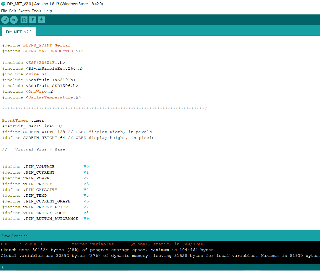.png)
1. Preparing Arduino IDE for Wemos Board
To upload the Arduino code to the Wemos board, you have to follow this Instructables
Set the correct board and COM Port.
2. Install the Libraries
Then you have to import the library on to your Arduino IDE
Download the following libraries
5.OneWire
3. Arduino Sketch
After installing the above libraries, paste the Arduino code given below.
Enter the auth code from step-1, ssid, and password of your router.
Then upload the code.
Downloads
Interfacing With Blynk App

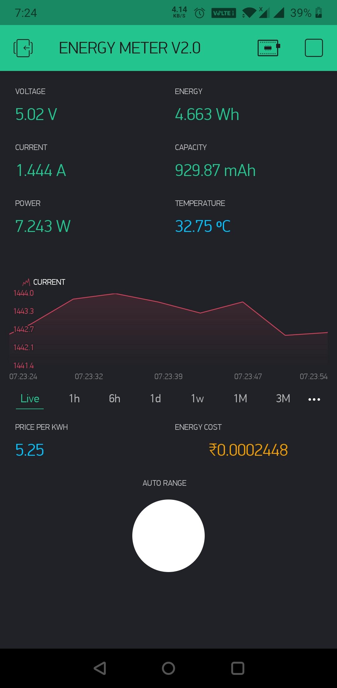
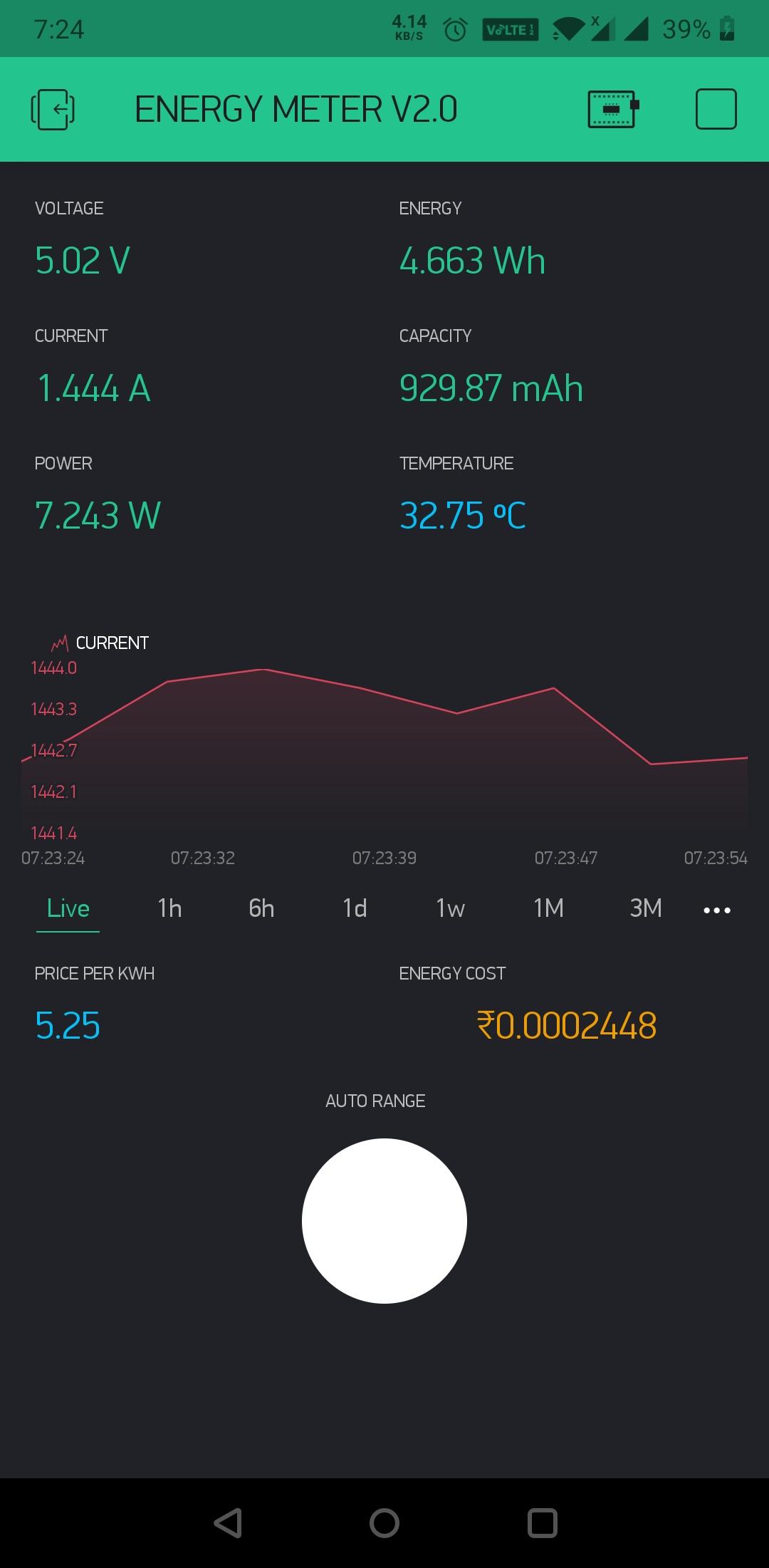
As the Wemos board has an inbuilt WiFi chip, you can connect it to your router and monitor all the parameters from your Smartphone. Here I have used Blynk app for making the smartphone monitoring app.
Blynk is an app that allows full control over Arduino, ESP8266, Rasberry, Intel Edison, and much more hardware. t is compatible with both Android and iPhone.
In Blynk everything runs on ⚡️Energy. When you create a new account, you get ⚡️2,000 to start experimenting; Every Widget needs some Energy to operate.
Follow the below steps :
Step-1: Download the Blynk app
1. For Android
2. For iPhone
Step-2:
Get the Auth Token In order to connect Blynk App and your hardware, you need an Auth Token.
1. Create a new account in Blynk App.
2. Press the QR icon on the top menu bar.
Create a clone of this Project by scanning the QR code shown above. Once it detected successfully, the whole project will be on your phone immediately.
3. After the project was created, Blynk team will send you an Auth Token over registered email id.
4. Check your email inbox and find the Auth Token.
Testing the Circuit
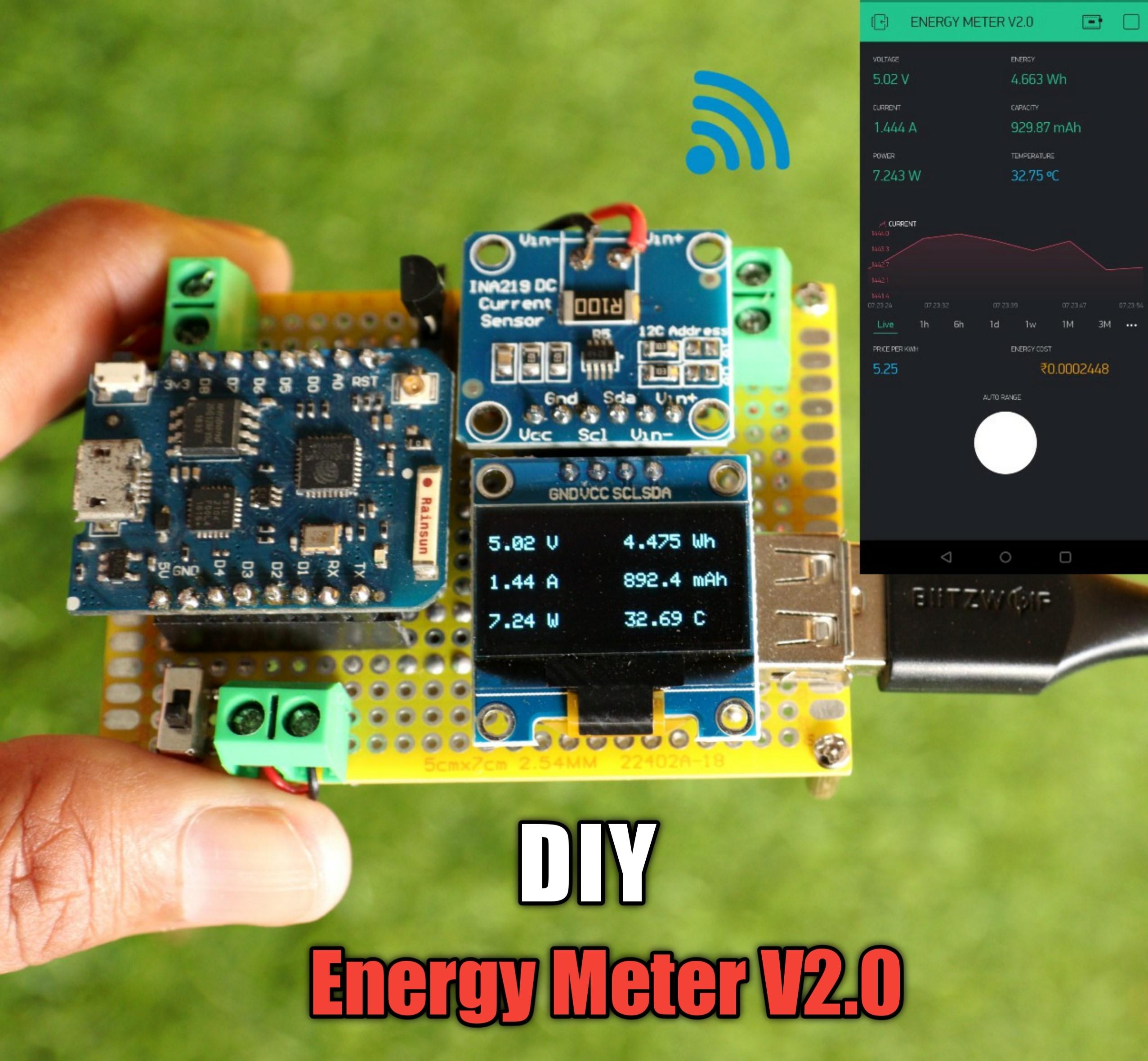
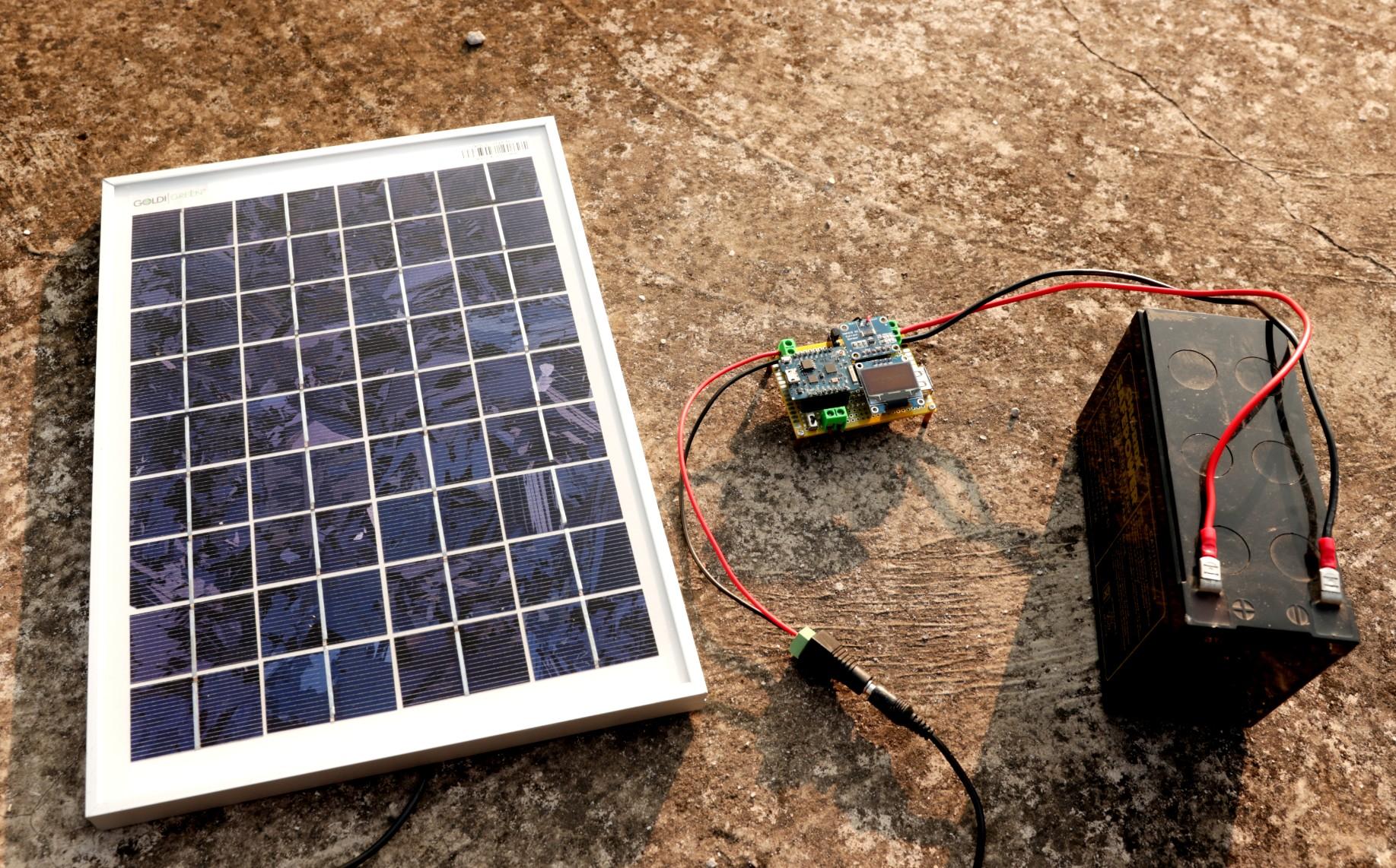
To test the board, I have connected a 12V battery as a source and a 3W LED as a load.
The battery is connected to the source screw terminal and LED is connected to the load screw terminal. The LiPo battery is connected to the battery screw terminal and then switch ON the circuit by using the slide switch. You can see all the parameters are displaying on the OLED screen.
The parameters in the first column are 1. Voltage 2. Current 3. Power The parameters in the second column are 1. Energy 2. Capacity 3. Temperature
Now open the Blynk app to monitor all the above parameters from your smartphone.
To check the accuracy I used my multimeter and a Tester as shown above. The accuracy is close to them.
I am really satisfied with this pocket-sized gadget.
Thanks for reading my Instructable.If you like my project, don't forget to share it.
Comments and feedback are always welcome.