DIY Macro Keyboard Using a Raspberry PI Pico
by not.vakesan in Circuits > Raspberry Pi
29032 Views, 21 Favorites, 0 Comments
DIY Macro Keyboard Using a Raspberry PI Pico
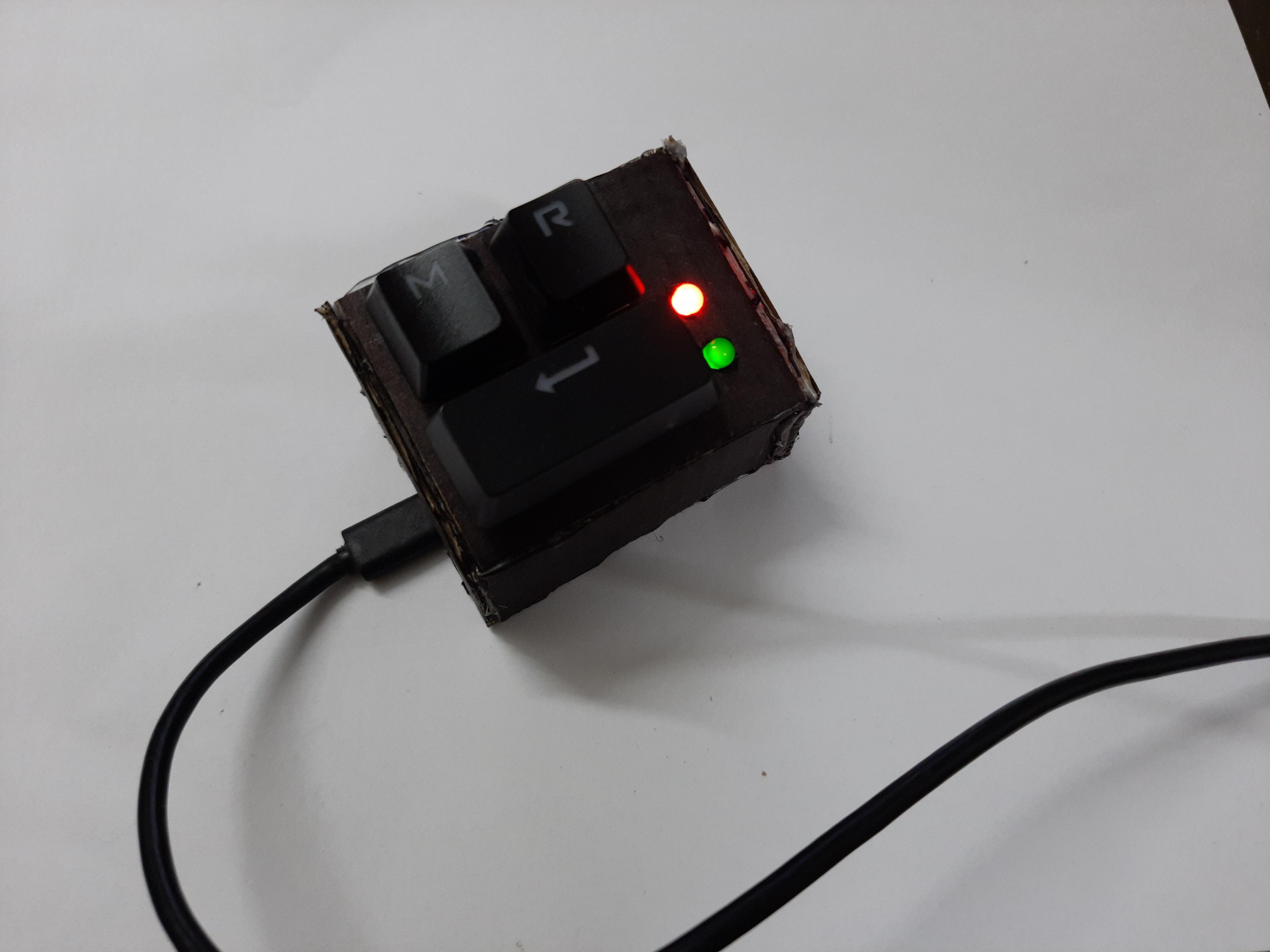
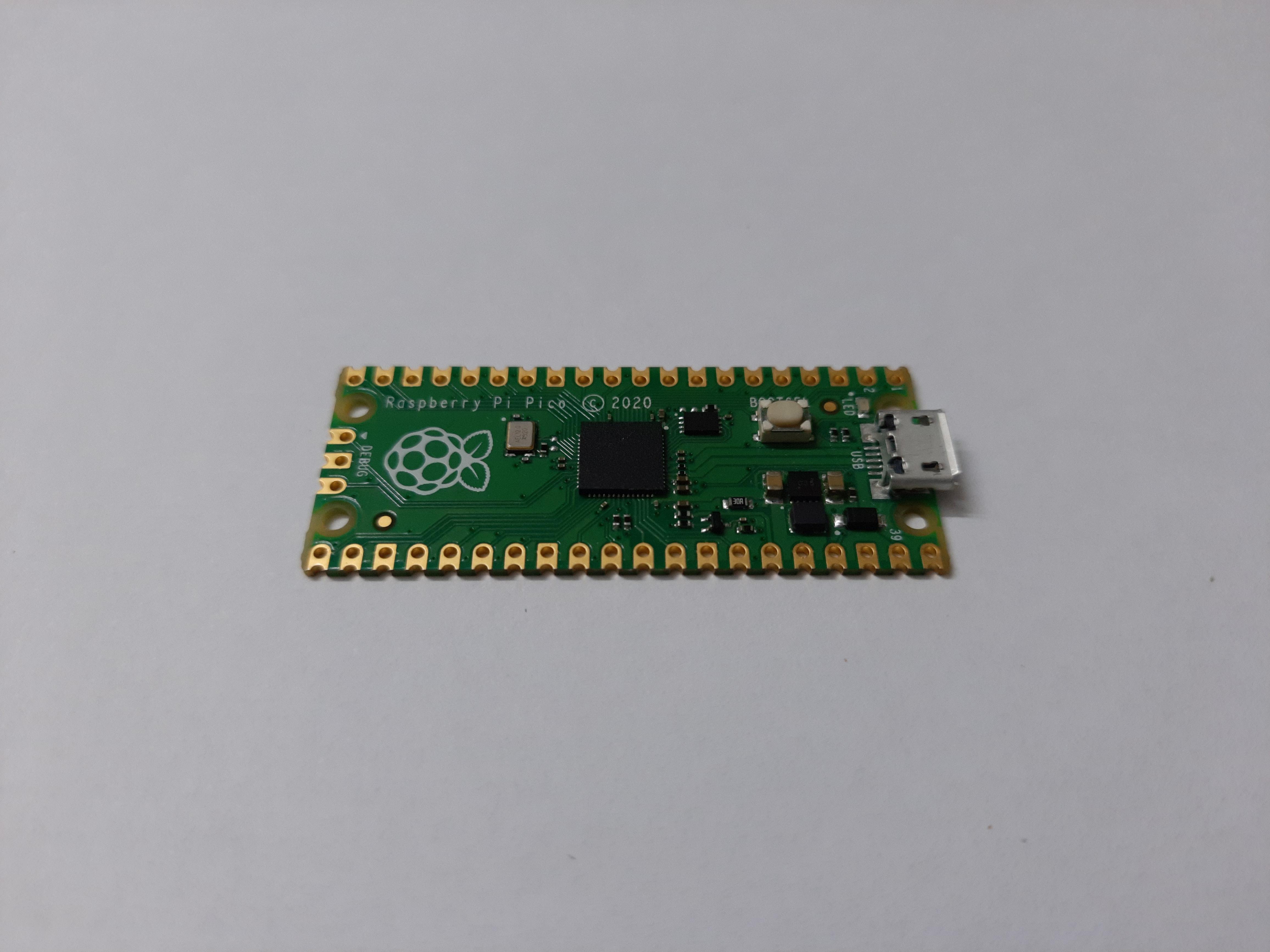
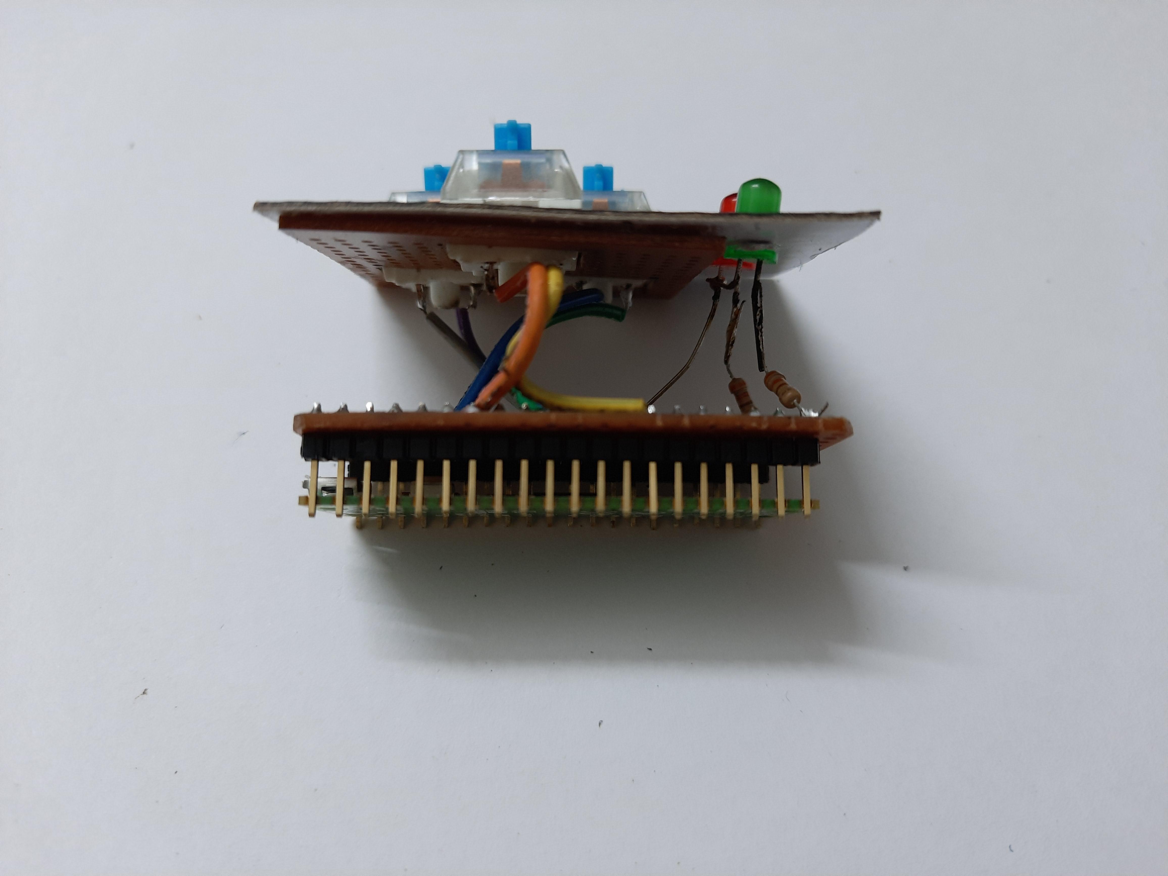
Have you ever wanted to make yourself a custom stream deck but didn't know where to start?
The Raspberry Pi Pico is just the thing you need.
Since the Pico supports USB interfacing it is very useful for making your own hotkeys and macros!
In this project I built a Macro with 3 buttons( for muting discord, Screen recording in OBS and a spare for future needs)
and 2 LEDs to show the mute and recording statuses.
Supplies
(x1) Raspberry Pi Pico
(x1) Micro USB cable
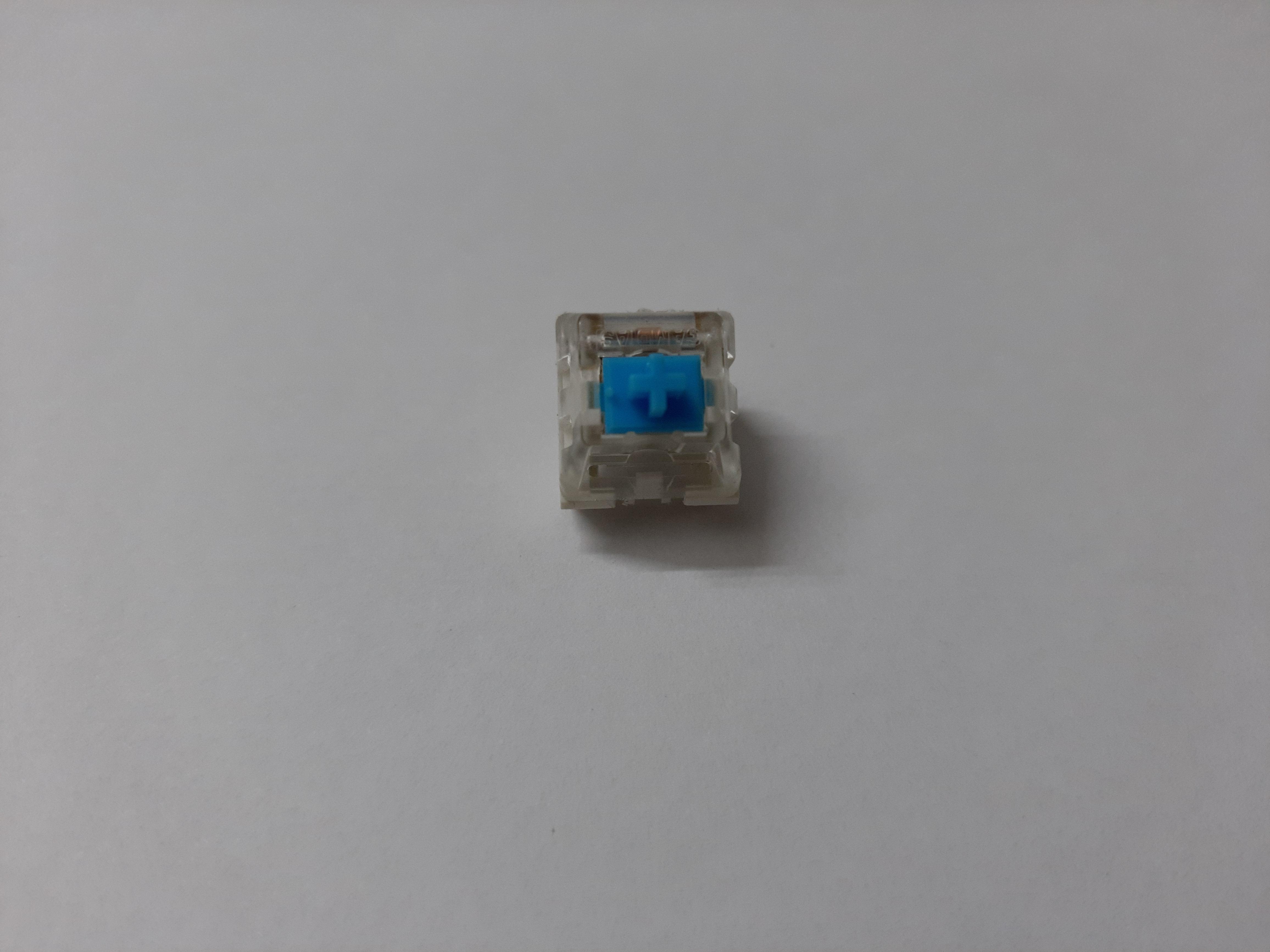
(x3) Push Buttons ( I have used some spare mechanical switches)
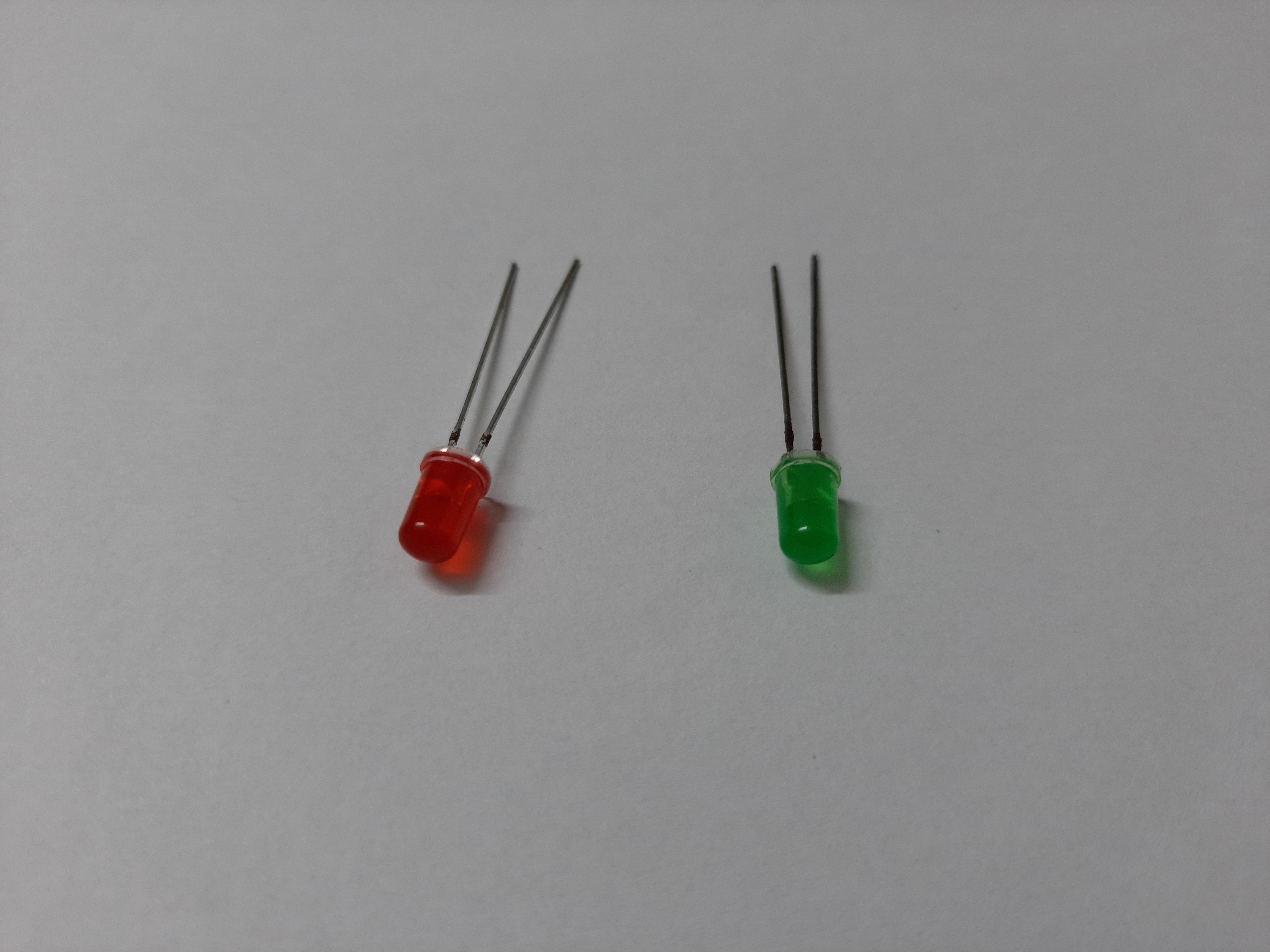
(x2) LEDs
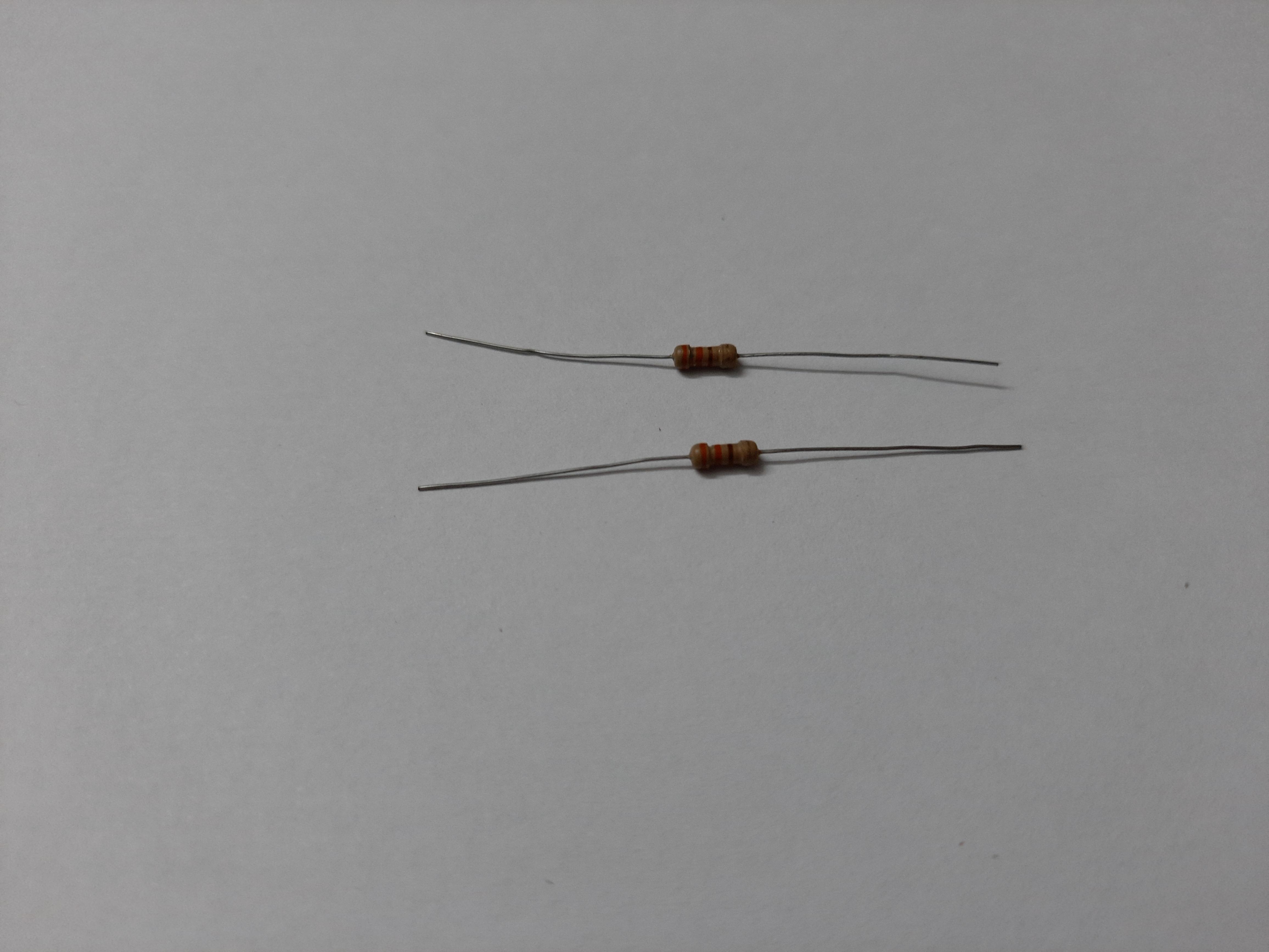
(x2) 330 ohm Resistors
Wires
Dot PCBs
Cardboard
Tools:
(x1) Soldering Iron
(x1) Wire Stripper
(x1) Hot Glue Gun
Setting Up the Pico and Testing
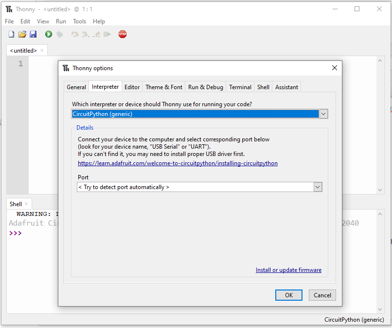
Since we are using the usb-hid libraries that aren't yet imported onto MicroPython yet, we will be using Adafruit's CircuitPython which has all the necessary libraries. We shall be using Thonny IDE to code the Pico.
Installing Thonny:
Head over to the Official Thonny Webpage and install the necessary application for your OS.
Downloading and uploading the CircuitPython UF2 file:
The UF2 file can be downloaded from CircuitPython Pico UF2 file.
Once downloaded, connect the Pico while pressing its BOOTSEL button. Drag and drop the UF2 file onto the storage folder that just opened and let the Pico restart.
Setting up Thonny:
Once you open Thonny go to Run > Select Interpreter
and make sure it is selected to CircuitPython(generic)
Type this command in the shell
help("modules")If everything is working until now you should see all the libraries that are already available.
Downloading required HID library:
To mimic Keypresses we need to download Adafruit's CircuitPython HID library.
- Go to the Adafruit's CircuitPython HID github repo
- Go to releases
- Download the zip file with mpy in it (example: adafruit-circuitpython-hid-6.x-mpy-4.1.6.zip )
- extract zip
- copy the adafruit_hid from the lib folder in the extracted folder
- paste it to the lib folder in the Pico which will now be called CIRCUITPY
Coding the Pico
Paste this code onto Thonny.
import board
import digitalio
import time
import usb_hid
from adafruit_hid.keyboard import Keyboard
from adafruit_hid.keycode import Keycode


keyboard = Keyboard(usb_hid.devices)


mute_pin = board.GP19       # pin to connect button to
record_pin = board.GP7
misc_pin = board.GP10
mute_led_pin = board.GP15   # pin to connect LED to
record_led_pin = board.GP16


# Initializing LED
mute_led = digitalio.DigitalInOut(mute_led_pin)
mute_led.direction = digitalio.Direction.OUTPUT
record_led = digitalio.DigitalInOut(record_led_pin)
record_led.direction = digitalio.Direction.OUTPUT


# Initializing Button
mute = digitalio.DigitalInOut(mute_pin)
mute.direction = digitalio.Direction.INPUT
mute.pull = digitalio.Pull.DOWN


record = digitalio.DigitalInOut(record_pin)
record.direction = digitalio.Direction.INPUT
record.pull = digitalio.Pull.DOWN


misc = digitalio.DigitalInOut(misc_pin)
misc.direction = digitalio.Direction.INPUT
misc.pull = digitalio.Pull.DOWN


mute_bool = False
record_bool = False


while True:
	# Check if button is pressed and if it is, to press the Macros and toggle LED
    if mute.value:
        print(" mute button Pressed")
        keyboard.press(Keycode.F14)
        time.sleep(0.15)
        keyboard.release(Keycode.F14)
        mute_bool = not mute_bool
        mute_led.value = mute_bool
    if record.value:
        print(" record button Pressed")
        keyboard.press(Keycode.F13)
        time.sleep(0.15)
        keyboard.release(Keycode.F13)
        record_bool = not record_bool
        record_led.value = record_bool
    if misc.value:
        print("misc button Pressed")
        keyboard.press(Keycode.F15)
        time.sleep(0.15)
        keyboard.release(Keycode.F15)
    time.sleep(0.1)
Note:
To run any code on the Pico automatically on start-up in CircuitPython the file must be named code.py
Electrical Connections
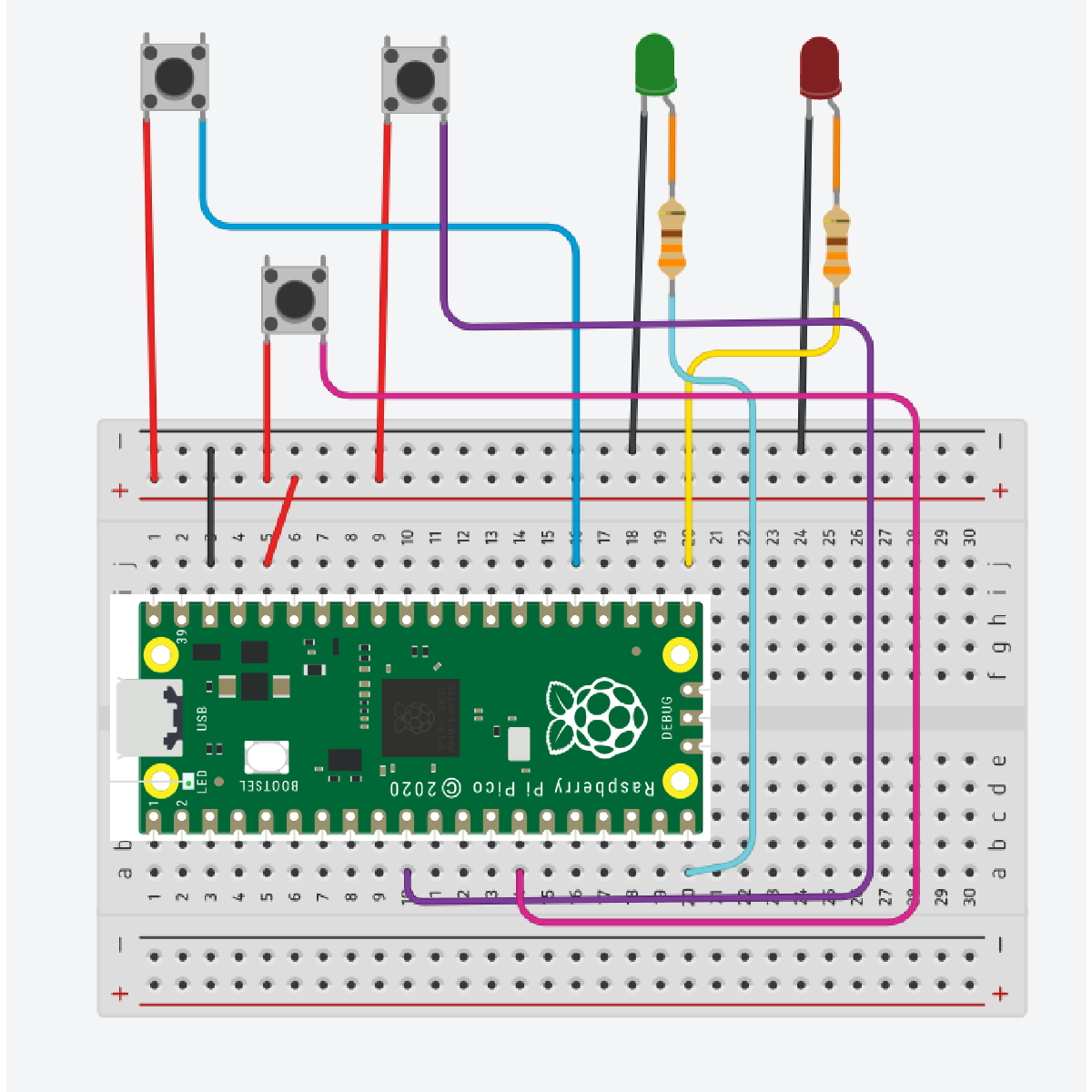
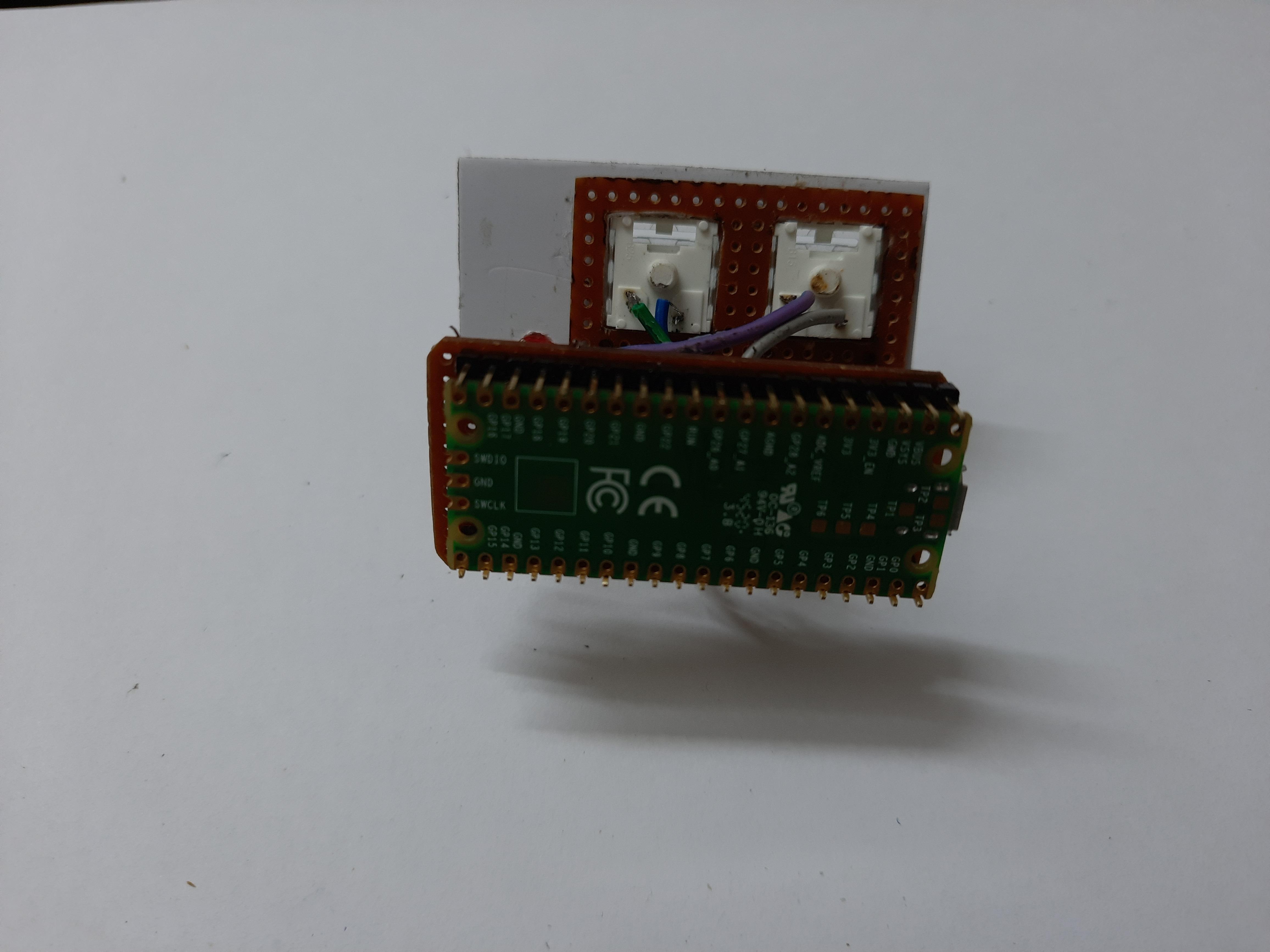
The connections are done as per the circuit diagram.
Both the LEDs are connected from GND to respective GPIO pins using a current limiting resistor.
The switches are connected from 3.3V to respective GPIO Pins, here pulldown resisters are not used as the pico supports pulling up/down a pin while initializing the pins.
Choosing Your Components and Layouts
Since the libraries are open source and the code is easy to edit the key macro combos are infinite and are only limited by your needs!
We first choose our switches, Push Buttons work just as well as any other button.
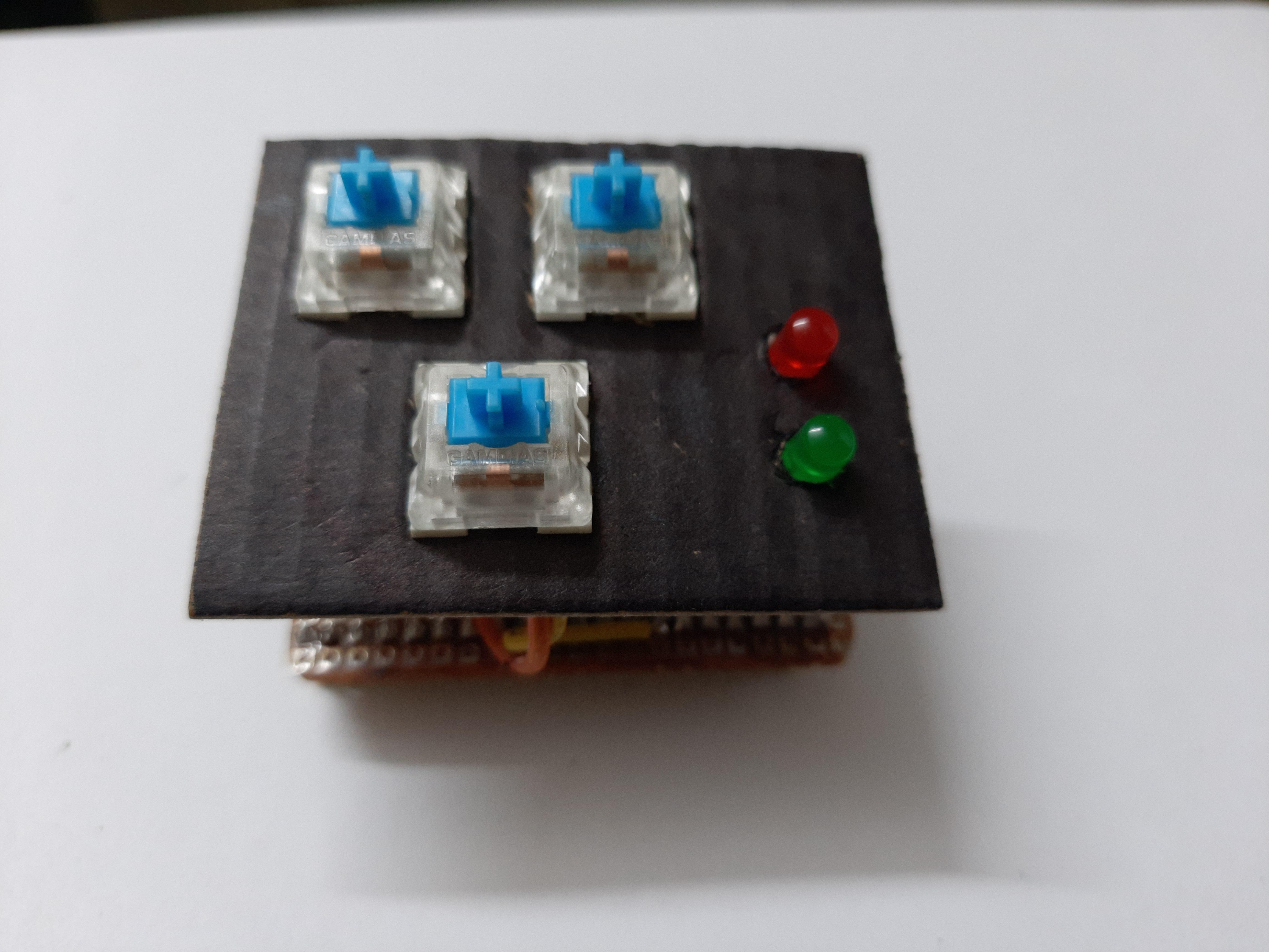
I used some mechanical switches that I de-soldered from my broken mechanical keyboard and also reused its keycaps.
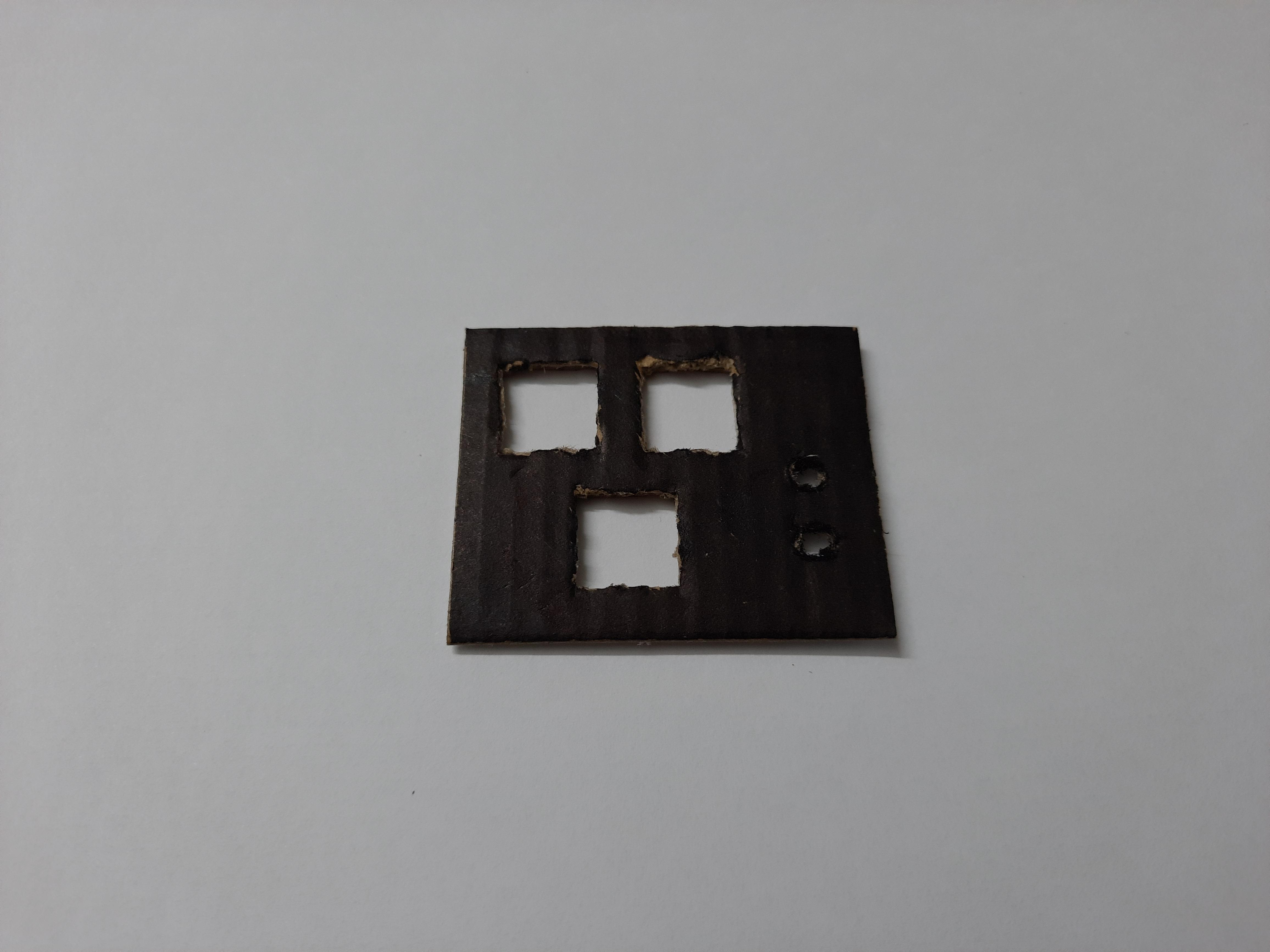
I wanted 3 keys so I cut my cardboard accordingly with holes for the LED also.
And made a suitable enclosure to fit them all.