DIY LED Array (Using Arduino)
by Wiring 1-2-3 in Circuits > Arduino
610 Views, 1 Favorites, 0 Comments
DIY LED Array (Using Arduino)
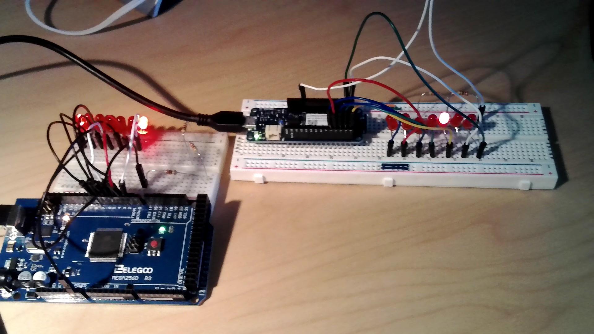
INTRO: Have you ever wanted to make a simple project that makes LEDs seem to be moving? No? That's what I thought. Well, if you ever have wanted to make something similar, you're in the right place!
Supplies
PARTS NEEDED:
3x 220 ohm resistor (The more 220s you have, the safer it can be!)
1x Breadboard
8x Jumper cables
7x LEDs (Red is the best because it is the most efficient color LED and it looks cool)
1x Arduino (Arduino MEGA, or Arduino MKR1000)
1x USB cable for Arduino
(OPTIONAL: A camera to take a vid to send to friends! :)
Building the Array:
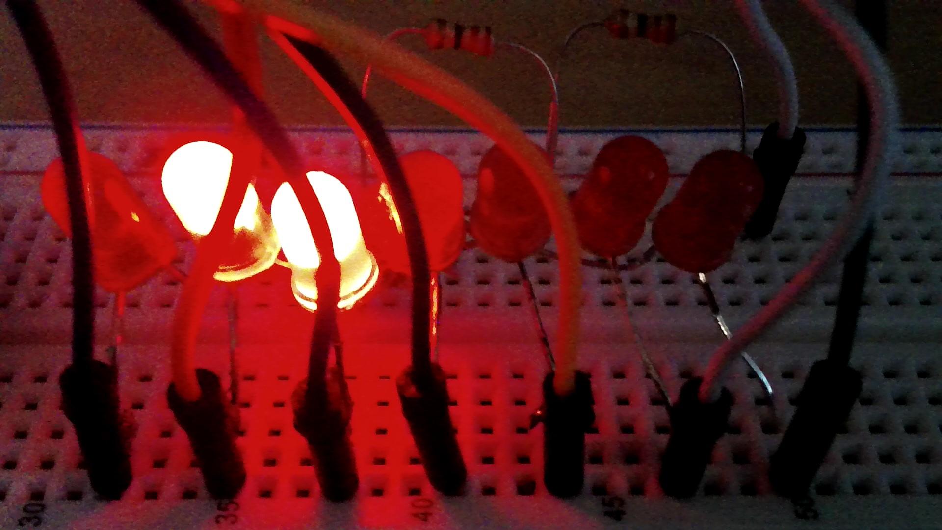
This step is simple. Solder 7 LEDs together, all Cathode/Negative pins together. That's it. You should have one GND leg connected to all cathodes of LEDs, and one Anode/Positive pin from each LED just floating in mid-air.
Connecting the Wires to the Arduino: (MKR1000)
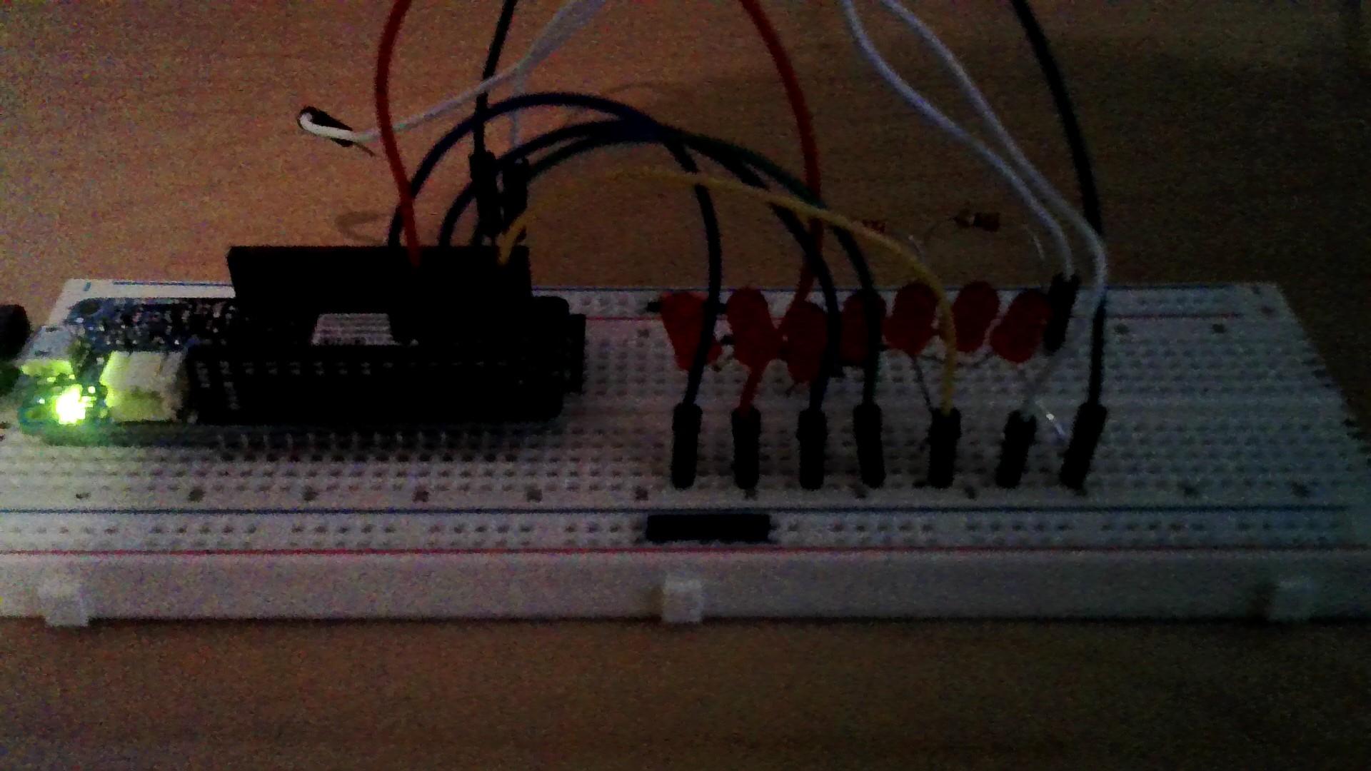
Now, if you are using the Arduino MKR1000, then stick with me. If you are using the MEGA, skip to the next step.
First, connect GND from your MKR1000 to your 220 ohm resistor(s). (the more, the better!) Then, connect the other end of the resistor(s) to the Cathode of all your LEDs. Great your almost there! Now, on the Arduino MKR1000, their are 7 pins, 1 through 7, excluding 0. So basically, connect your LEDs in order (ex. 1st LED to 1, 2nd LED to 2, etc.) Once you are done, your wiring should look something like these:
Some more pictures: IMAGES!!!!!!!
Connecting the Wires to the Arduino: (MEGA)
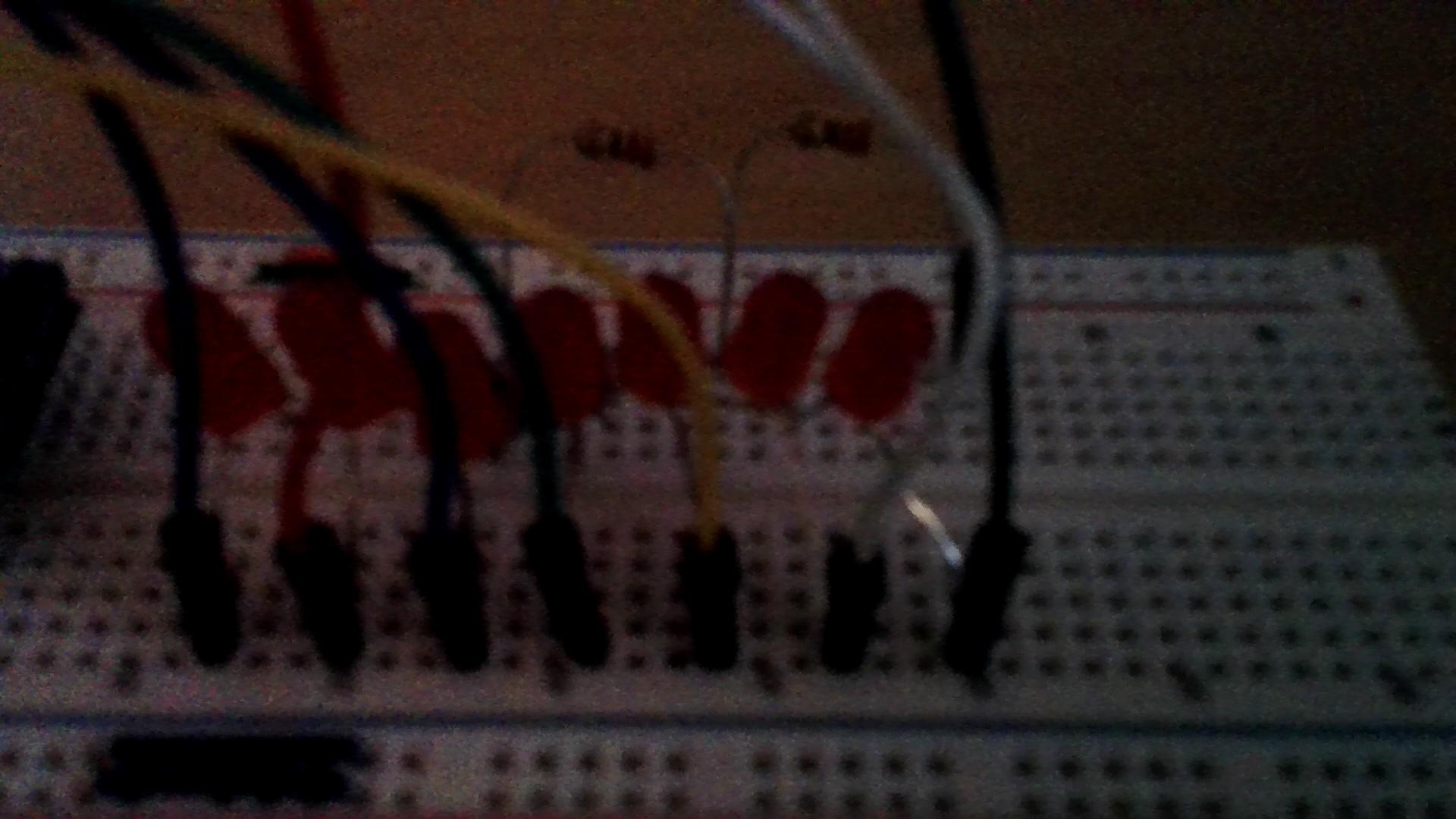
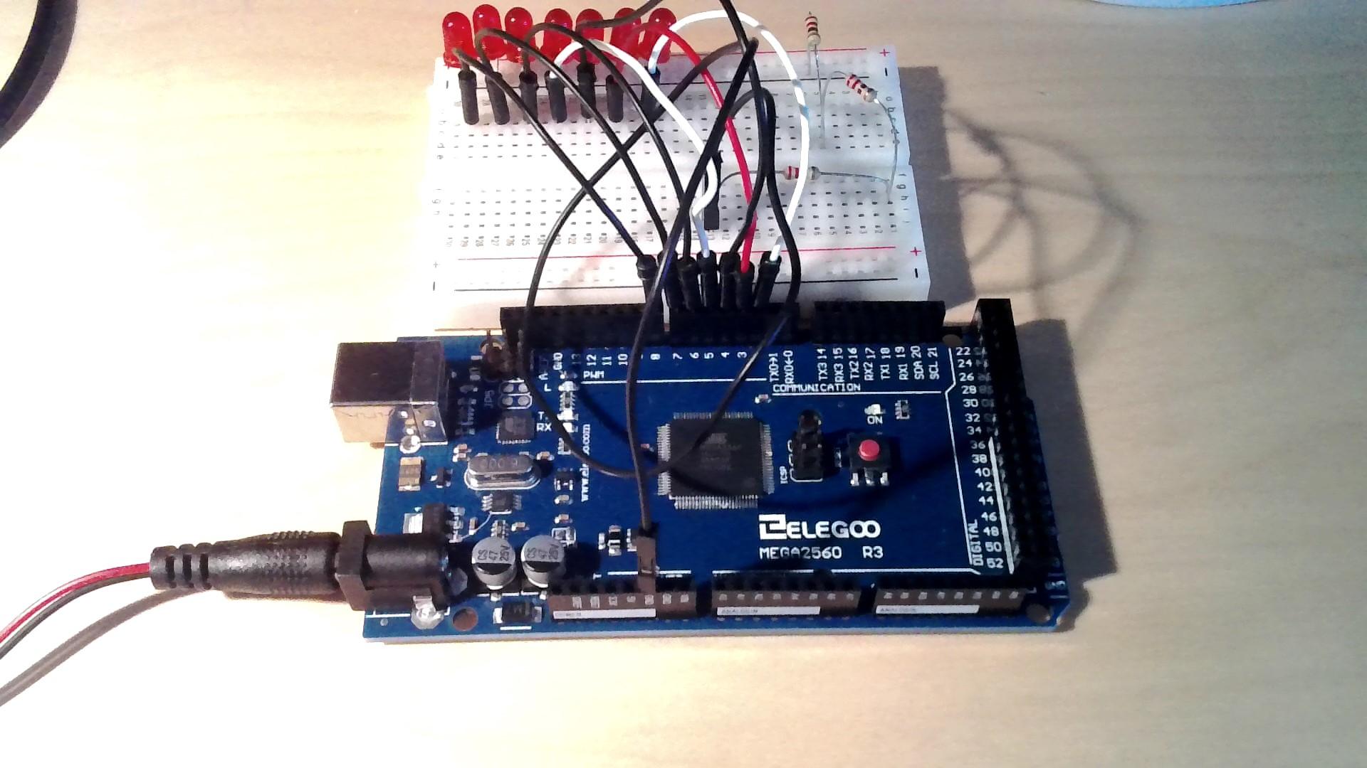
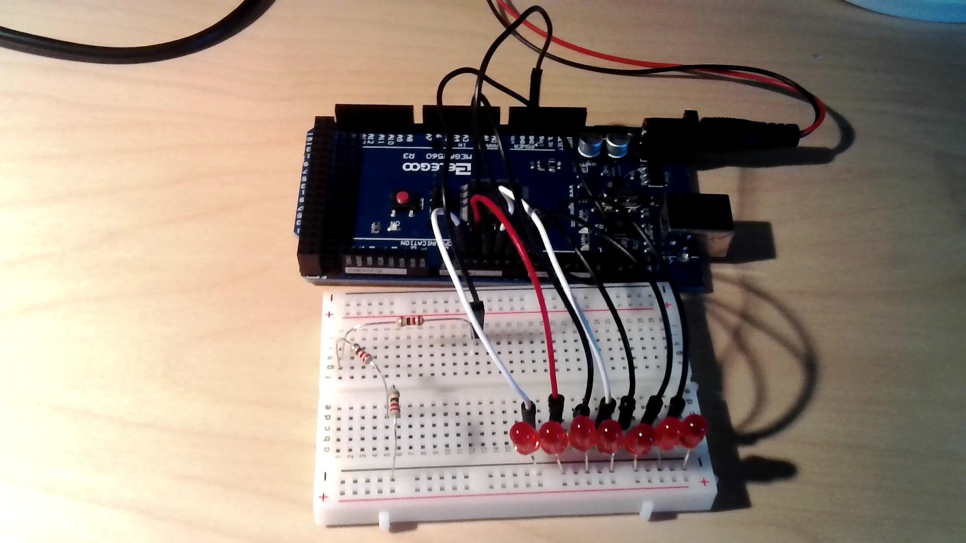
In this step, we will connect the wires from the LEDs to the Arduino MEGA. If you are using the Arduino MKR1000, go back a step.
The Arduino MEGA's wiring connections are pretty similar to the ArduinoMKR1000's. (Keywords in that sentence are "pretty similar", So don't mess this up, and pay attention!) Start out by connecting GND on the MEGA to the 220 ohm resistor(s). (The more resistors , the better!) Then, connect the other end of the resistor(s) to all the Cathodes of your LEDs. Yay! You got by the easiest part! Now, this is where it gets a little bit tricky. We will be using pins 2 through 8 for this project. Connect your LEDs in order. (ex. 1st LED to pin2, 2nd LED to pin3, etc.) Once you have done this, you're in the home stretch!!!
Here are some more images that may help: IMAGES!!!!!!!
Code For: ARDUINO MKR1000
Here is the code: MKR1000
Code For: ARDUINO MEGA
Here is the code: MEGA
Testing Time!
Hooray! You finished! Don't get too excited yet, we still need to test it! Simply plug it in using the USB cable, or power it using an external power supply. Does it work properly? If you aren't sure if it is working correctly, check out the next step to see the video of it working correctly!
All Done!
Check this out! It works