DIY: IR Remote Controlled Home Automation
by ProjectMaestro in Circuits > Arduino
868 Views, 4 Favorites, 0 Comments
DIY: IR Remote Controlled Home Automation
.png)
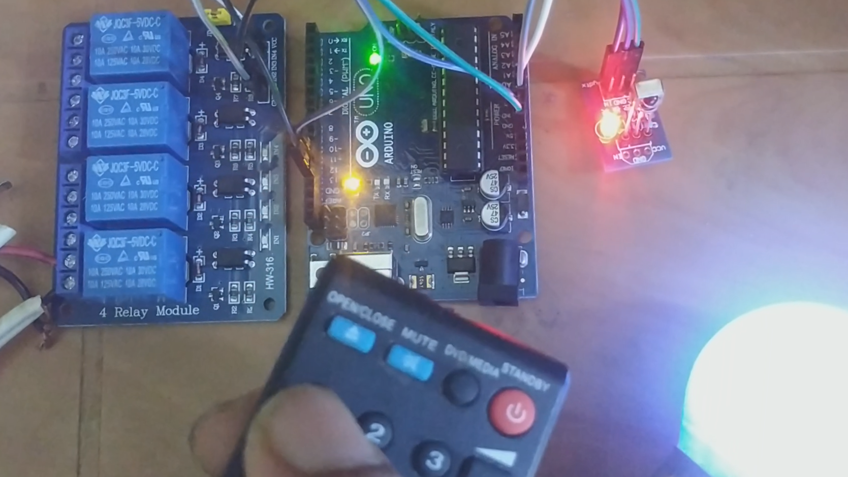
In this tutorial we will learn how to interface IR Remote with Arduino and control Relay Switch with remote to turn on and off a AC current powered Bulb. This is a great project for lazy people like me, who do not wish to get up from the bed just to switch off the lights and fans.
WARNING: First, if you have zero experiences working with AC voltage, please be sure, it can be deadly. So take proper safety precautions before working with AC voltage. You can wear rubber sandals and non conductive gloves to avoid contact with ground and bare wires.
Supplies
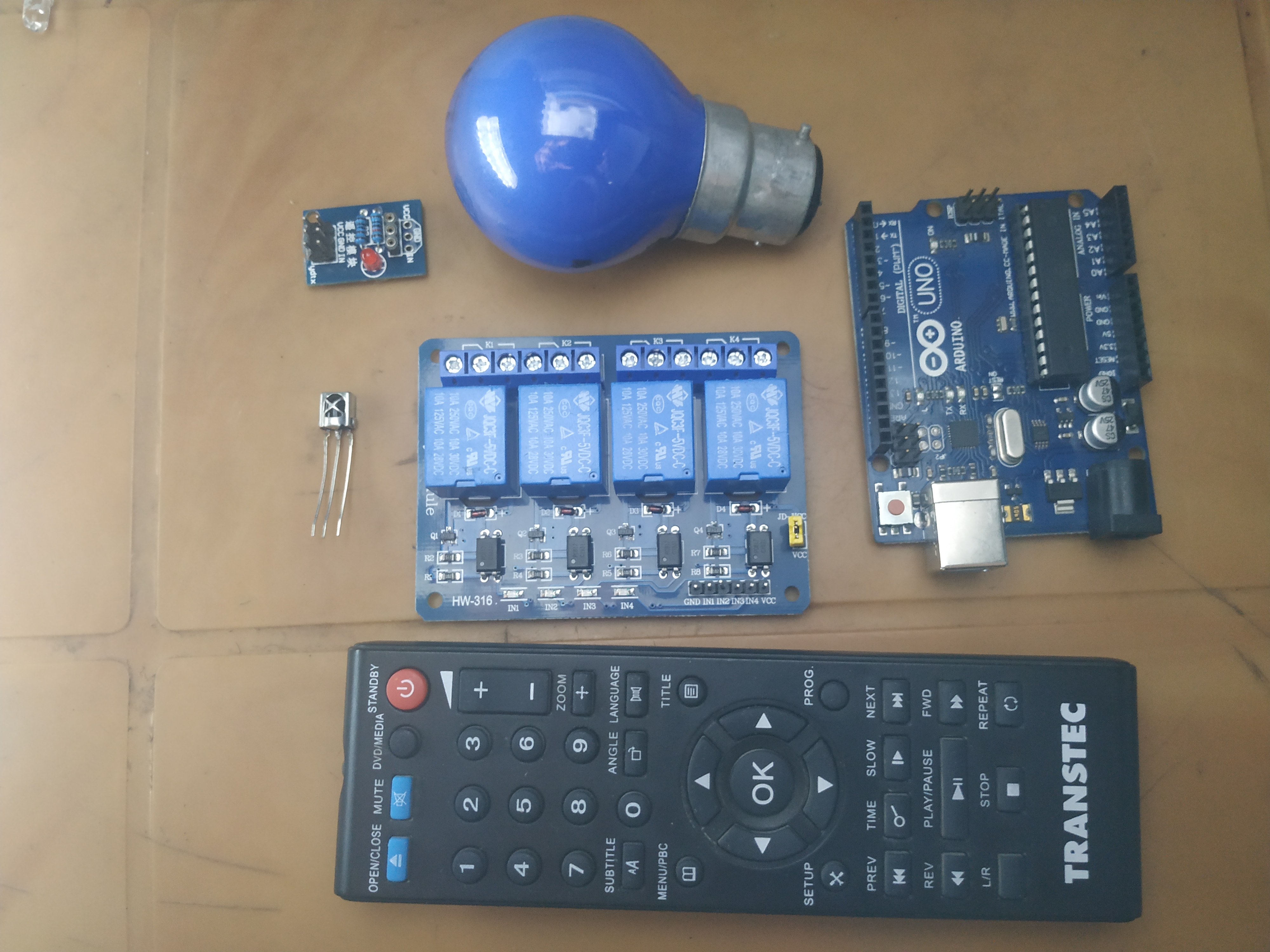
- Arduino Uno R3 (Any Arduino will do)
- IR Receiver (VS1838b) along with its module. The receiver can be bought standalone or with the module (which consists of necessary resistors and capacitors for its proper power delivery)
- 5V Relay switch that can support 110V~250V AC Voltage and 10Ampere current(I have used a 4 channel relay switch, as I will use it for controlling fans and lights of my room. You can use any number of channel depending on your needs. Single Channel, 2-channel, 4-channel, 8-channel and even 16-channel relay switch are available in the market).
- A remote controller from a old DVD. You can use any remote control that uses IR to control device. If you have mobile phone with IR blaster, you can also use that.
- Bulb, breadboard, wires etc.
Getting Started With IR Remote and IR Receiver.
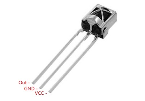
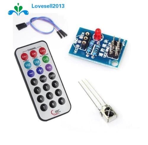
The IR receiver that we will be using here is VS1838b. The pinout is shown in the diagram. It can be purchased with a module where is can seat and you do not have to think about the resistors you need to connect with the receiver for its proper power delivery and functioning.
The module has VCC, GRND and IN that corresponds to the VCC, GRND and OUT of VS1838b.
To power up the module connect VCC to 5V, GRND to GRND and OUT of the module to the receiving pin(I used D11) of ARDUINO respectively.
Now, FYI, every button of remote controller with an IR blaster sends a code, more specifically pulses of invisible infrared light that corresponds to certain binary code. Every button has unique set of pulses. So, we need to know, what the code the button sends. since binary code corresponding to the pulse can be really really long, they are often viewed in Hexadecimal format.
So lets get started. Connect the the IN of the module to pin 11 of Arduino. Download the IR Remote library if you do not have and install the library. To do so, follow the first two steps and if you have, start from step 3:
- To download IR remote library click on to: http://downloads.arduino.cc/libraries/github.com/...
To install the library, open Arduino IDE, then Sketch ->Include library -> Add .Zip file and locate the file to add the library.
Open Arduino IDE, then File->Examples->IRremote-> IRrecvDemo
Upload the code to your Arduino.
Open Serial Monitor and click buttons of the Remote controller to see the Hexadecimal code of each buttons.
Congratulations, you are ready to use the remote as your next DIY playing tool.
Playing With the Remote
Now as you can see the codes behind each button you can simply start using the remote to control devices (DC devices of course for now). Just try some simple codes to turn on and off the built-in LED, or control some servo motors. You are gonna enjoy playing, trust me :D
Getting Started With Relay Switch.
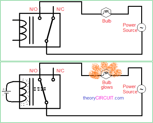
A relay is an electromagnetic switch that can be operated by a relatively small electric current which in turn can control switching a device that needs huge voltage or current to run. The relay is an electromagnet (a coil of wire that becomes a temporary magnet when electricity flows through it). When small current flows through the coil it gets energized and thus switches in between its states. There are two positions : NC(Normally Closed) and NO (Normally Open). Relay can be also thought as a SPDT (Single Pole Double Through) switch. when it is not energized, the pole remains in a closed connection to NC, when the coil is energized, the pole gets connected to NO, thus making it possible for small currents to activate larger ones.
The Relay I have used can handle 110 to 250V AC voltage and can allow 10A current through it, which is good enough for controlling almost all electrical appliances in our home. It can be energized through 5V received from Arduino.
I have bought a 4 channel relay as I have 3 lights and 1 fan in my room. You can buy any number of channels as necessary for your DIY Home automation.
Control Your Relay Switch to Lit a Bulb
WARNING: AC VOLTAGE CAN BE DEADLY. PLEASE BE SURE WHAT YOU ARE DOING
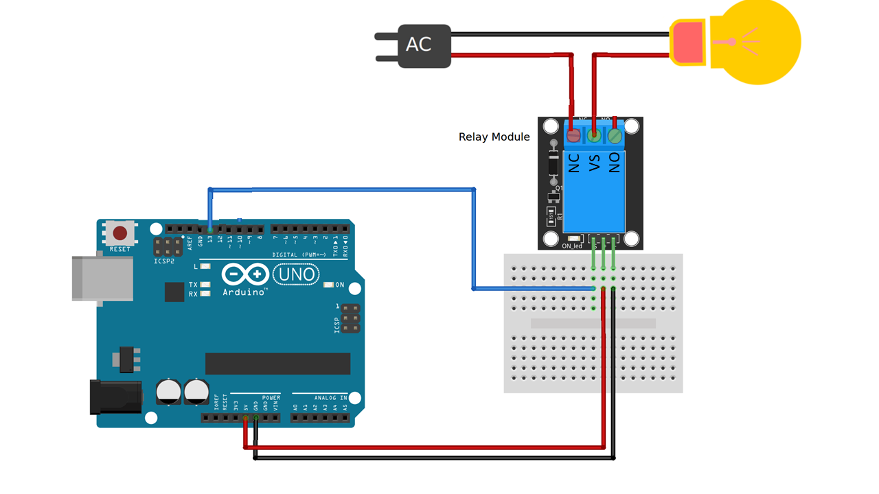
Take a wire that has a plug connected and check for the Phase of the line (AC Current has 2 wires, one is neutral and the other being the phase). Connect the phase to the center of the relay (VS).
Then take a bulb, wire it and get one of the wire attached to the neutral of the AC line and the other connected to the NC of Relay (I have planned to keep the bulb lit up if there is no 5V signal to energize it, as you know Arduinos can be unpredictable and can die at anytime and thus I will be able to manually switch on-off the light/appliances if necessary)
The circuit diagram has been attached. please connect accordingly.
The code can be downloaded from this link
https://drive.google.com/file/d/17meFvvfqIHnLrokSo...
So that's it. You are done and ready to do your own coding and play.