DIY Home Alarm System Using Arduino
by callmeappytechie in Circuits > Arduino
15975 Views, 48 Favorites, 0 Comments
DIY Home Alarm System Using Arduino

Hi, guys!!! I'm Sridhar Janardhan back again with another instructable.Today I am going to deal with Arduino Based Home Alarm System.The cost of the whole project cost you less hand 10 $.It is very handy and compact in size.If anyone has missed out my previous ible "Control Servo Using PIR Sensor" Click on the text.
Now let's get started by gathering the tools and Components required for this ible.
Gathering Components :


The components required for making out this Instructable are:
- Ultrasonic Sensor
- Arduino Uno
- Piezo Buzzer
- Breadboard
- LED
- Jumper wire
- Thermocol (Optional)
- Thermocol cutter (Optional)
Hope you all collected the required sources for this tutorials
Connecting Ultrasonic Sensor:


Before the connection, i would like to explain "What is Ultrasonic sensor??"
An Ultrasonic sensor is a device that can measure the distance to an object by using sound waves. It measures distance by sending out a sound wave at a specific frequency and listening for that sound wave to bounce back. By recording the elapsed time between the sound wave being generated and the sound wave bouncing back.This seems similar to the working of Sonar and Radar.
The connection of the Ultrasonic Sensor to the Arduino:
- GND pin (Black wire) is connected to the Ground railings on the Breadboard.
- VCC pin (Red wire ) is connected to the Positive railings on the Breadboard.
- Echo pin (White wire)is connected to the Digital pin 9 of the Arduino.
- TRIG pin(Orange wire)is connected to the Digital pin 10 of the Arduino.
After finishing the above procedure, We concentrate our next interfacing of Piezo buzzer.
Connection of the Piezo Buzzer.


The connection of the piezo buzzer:
The buzzer got two wire coming out of the enclosure.The Red wire indicates the Anode or Positive Terminal.The Black wire indicates the Cathode or Ground terminal.Before connection, the Piezo buzzer wire are extended using a male to male jumper wire as shown in the picture
- The Red wire or Positive terminal is connected to the Digital pin 13.
- The Ground wire is connected to the negative railings of the Breadboard.
After the connection of Piezo Buzzer, you are done with the circuit except interfacing an LED.let's get into that business.
Connecting LED:


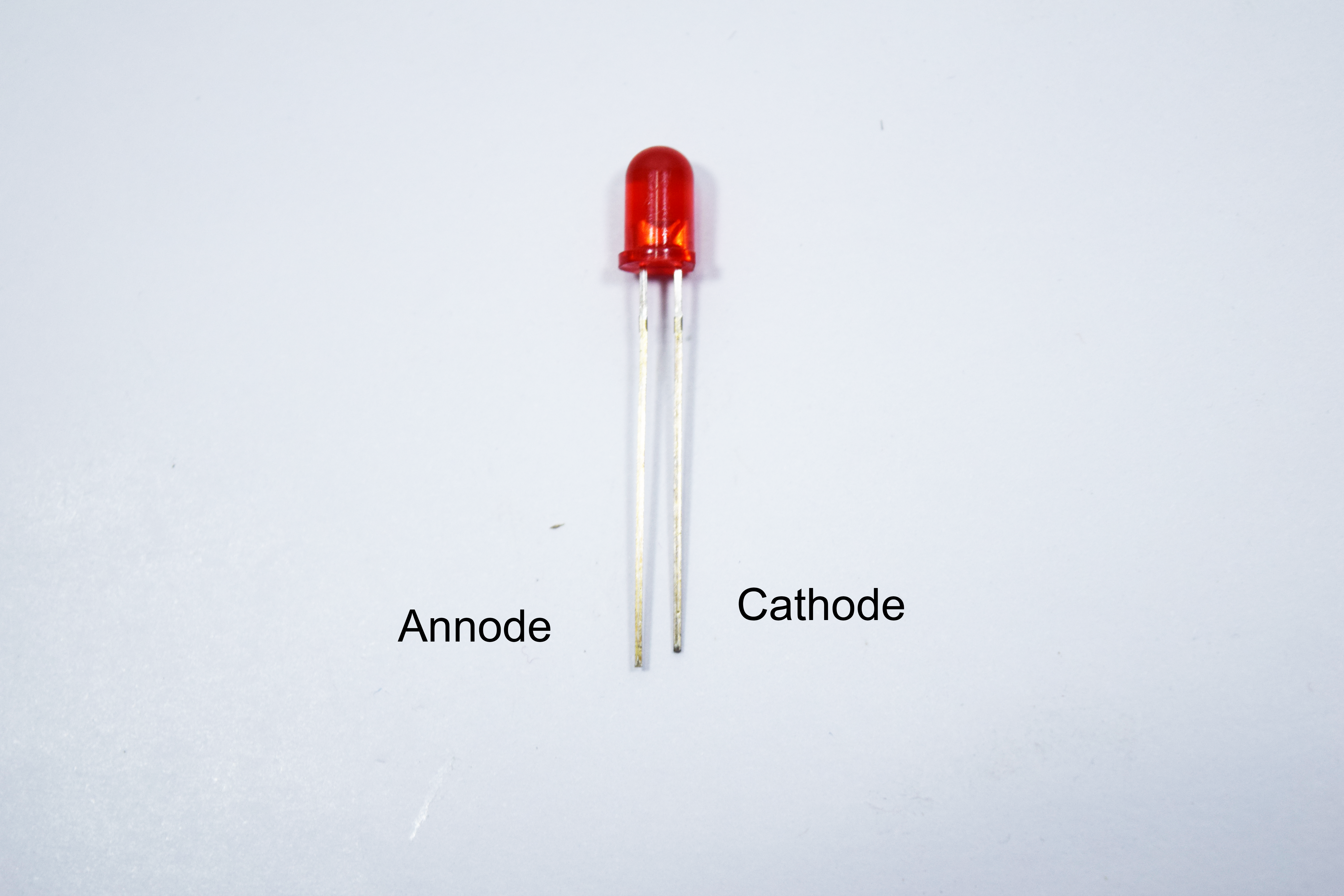
The LED has two terminals, The long leg is called as Anode and the short leg is called as cathode.
LED is now placed on a breadboard, The longer leg is connected to the Digital pin 13 and the shorter leg Cathode is connected to the negative railings of the Breadboard.
This completes the interfacing of the hardware in the circuit.Let's get into the coding of the Microcontroller.
Coding:

const int trigPin = 9;

const int echoPin = 10;

const int buzzer = 11;

const int ledPin = 13;

long duration;

int distance;

int safetyDistance;

void setup() {

pinMode(trigPin, OUTPUT);

pinMode(echoPin, INPUT);

pinMode(buzzer, OUTPUT);
pinMode(ledPin, OUTPUT);
Serial.begin(9600);
}
void loop() {
digitalWrite(trigPin, LOW);
delayMicroseconds(2);
digitalWrite(trigPin, HIGH);
delayMicroseconds(10);
digitalWrite(trigPin, LOW);
duration = pulseIn(echoPin, HIGH);
distance= duration*0.034/2;
safetyDistance = distance;
if (safetyDistance <= 5){
digitalWrite(buzzer, HIGH);
digitalWrite(ledPin, HIGH);
}
else{
digitalWrite(buzzer, LOW);
digitalWrite(ledPin, LOW);}
Serial.print("Distance: ");
Serial.println(distance);
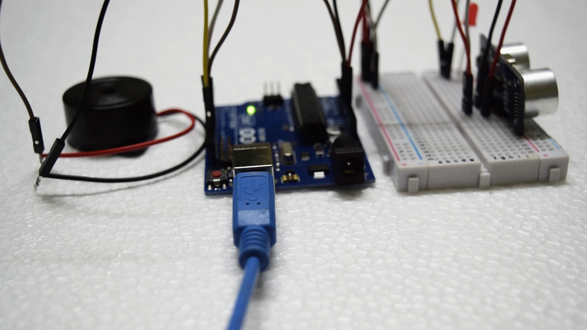
}The Execution :

Any Assistance:
If you need any assistance in any electronics categories mail me your project Abstract to official.appytechie@gmail.Feel free to leave a comment below so that I can get you better Projects and Instructables.
Thank you,