DIY Grow Light

This project stemmed from my love of house plants and the fact that I needed a senior capstone idea for my university studies. Despite how straight-forward I thought this project would be, it ended up taking different forms and hitting many roadblocks. To see the final video of the project, click here.
Formatting:
If a link has been provided outside the supplies list, the words to click on will appear as italicized, underlined, and orange.
Table of Contents:
- Supplies
- Supplies that Worked
- Links and Shopping List
- Supplies that Didn't Work
- Links
- Previous Attempts
- 12V 2 Channel Relay Setup
- IoT Relay Setup
- Circuitry / Coding
- Setting Up the Coding Environment
- Instructions
- Files
- Troubleshooting
- 3D Modeling / Printing
- Setting Up the Modeling Environment (Optional)
- Instructions
- Files
- If You Do Not Have Access to a 3D Printer
- Troubleshooting
- Assembly
Supplies
Supplies that Worked (Shopping List):
- 5V 1 Channel Relay
- Interfaces with 2-pronged lamp cord
- Hanging Ceiling Lamp Cord (2-Pronged)
- Interfaces with relay
- Arduino Uno
- Microcontroller that sends signals to the relay module to control the grow light
- I've used Arduino Unos for years, so I chose this one, but you can use whichever microcontroller you are most familiar with
- Real Time Clock
- Keeps track of the passage of time without delay
- A microcontroller can glitch or delay if it's keeping track of large amounts of time
- Dimmable LED Grow Light Bulbs
- Allows user to replace bulbs if they're burnt out or if a different bulb wavelength is desired
- Can be dimmed via remote control if regular light is too strong for plants
- Breadboard and Jumper Wires
- Necessary for Arduino circuit wiring
- Female to Male Jumper Wires
- Necessary for plugging the relay into the Arduino
- Buttons
- To program to control light brightness and timer
- 9V Battery Connector
- Necessary for plugging the 9V battery into the Arduino
- 9V Battery
- Powers the Arduino instead of a computer
- Multimeter
- Allows you to check lamp cord's power/ground wires, see if your circuitry is set up correctly
- Mini Screwdrivers
- Necessary for securing lamp cord wires to the 5V relay
- Wire Cutters, Wire Stripper, and Exacto Knife
- Needed for accessing the wires in the lamp cord
- You can also use a box cutter instead of an Exacto Knife
- Soldering Iron Kit
- For connecting buttons to wires
- Digital Caliper
- Gives you precise measurements if you choose to model your own grow light shell
- PLA Filament
- For 3D printing your grow light shell
- I used PLA filament because that is what the lab I work in has, but you can do your own research on other types of filaments or use a pre-built box (be sure it does not conduct electricity)
- Hot Glue Gun
- Works as an insulated adhesive for circuitry
- Super Glue
- For gluing parts of your 3D printed shell together if it is too big to print at one time
- Double Sided Nano Tape
- Allows for a strong yet removable adhesive to be the attachment method of the grow light
- Electrical Tape
- Provides insulation for exposed wires and soldered connections
- #6 Screws (Any Length)
- Allows for a more secure attachment method
- 3D printed shell has holes that fit #6 screws
Supplies that Didn't Work:
- 12V 2 Channel Relay
- Might require a 3-pronged lamp cord
- Wire Sockets
- Cannot split the power cord easily
- IoT Relay
- Does not allow for Arduino-based dimming
- Has an "always on" outlet that renders the Arduino useless
- Socket Adapters (For IoT Relay)
- Doesn't allow for power cord splitting
- Regular LED Grow Lights
- Does not allow for dimmable light feature
- However, you can build a manual dimming system, like 3D printed sliding grates or blinds
Previous Attempts and Research
.jpeg)

12V 2 Channel Relay Setup:
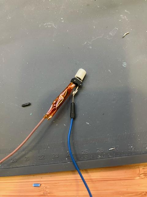
The initial version of this project utilized a 12V 2 channel relay and wired sockets. This required a 3-pronged light socket to be wired into the channel, and unfortunately, I did not have that on hand. With this, I was not able to turn on the lightbulb.
IoT Relay Setup:
The second version of this project used an IoT relay and plug sockets. This system worked better than the 12V 2 channel relay at first purely because it could turn the bulb on. However, this did not allow for the relay to interface with a dimmable bulb. I reached out to the manufacturers who confirmed that the relay would either power on HIGH or LOW, and no in between. Therefore, the dimmable bulb could not function. I also managed to fry my Arduino Uno by using an AC/DC charger that did not match what was required to power the Arduino, a video of which is included below. If you choose to use a large external power supply (which is not required in this Instructable), double check the power is within Arduino operating limits.
First Iteration of Final Project:
When building the final version of this project (which the Instructable is based on), it ended up overloading the circuit once inside the box and exploded. I rebuilt the project and tested various parts of it to make sure I understand where it went wrong. What I learned is:
- Normal PLA filament is non-conductive. It is safe to put the circuitry inside a PLA box. If you are unsure about if the PLA you are using, check its conductivity using a multimeter.
- The socket I was using did not sit fully in the lamp cord. To avoid any wires potentially coming into contact with it, I applied electrical tape to the exposed part of it (link in shopping list). I also applied electrical tape to the exposed part of the battery clip.
- Stagger the power and ground cords on the breadboard (do not have them directly next to each other). If the wires slip out a little bit, them being next to each other will increase the risk of them touching and short circuiting. I recommend placing them diagonally from each other while following the flow of the current (an explanation of how breadboards work is in the troubleshooting section of Step 5: Assembly).
- If the relay is ever flickering rapidly instead of staying on/off steadily, immediately disconnect everything from a power source (the Arduino from the battery, the lamp cord from an outlet, etc.).
- To ensure everything is as insulated as possible and wires don't slip around, use hot glue (which is insulating) to secure wires to the Arduino and cover exposed wires in the relay. To remove the hot glue, use rubbing alcohol.
Research:
- The timer settings on the grow light are reflective of the University of Missouri Extension's research on caring for houseplants. Using artificial lights, houseplants should get up to 16 hours of light each day, so I created 3 timer settings (8, 12, and 16 hours).
- Their research on light for different houseplants also suggests that there are typically 1 of 3 light requirements (low, medium, and high). I have modeled the grow light to be able to fix on a shelf or wall to provide direct and indirect light to plants. A summary of the University of Missouri Extension's research will be included below.
- Low light plants: palms, pothoses, philodenrons, snake plants
- Medium light plants: ferns, figs, pines, monsteras, jade plants
- High light plants: cacti, succulents, herbals (lavender, jasmine), orchids
- An Arduino (or most microcontrollers) alone will not be able to handle keeping accurate time for multiple hours. In order to avoid errors in timing, I decided to use a battery-powered Real Time Clock that needs to be set only once and will run as long as the battery connected to it has power (even if the microcontroller is off).
Downloads
Circuitry Setup


Setting Up the Coding Environment:
If you have not used an Arduino before, it requires a specific coding environment called the Arduino IDE. Click here to go to the Arduino IDE website and download the software that is compatible with the computer you are using. As of the time of the creation of this Instructable, the Arduino IDE 2.3.2 is the version you should download. Follow along with the instructions and pop up commands to set up the IDE.
Next, grab your Arduino and the adapter that came with it. If you do not have a USB port in the computer you are working with, you will need another adapter to connect the Arduino adapter to your computer ports. Plug in the Arduino to your computer and open the IDE. In the top left corner, there is a dropdown menu you should click on. If your Arduino Uno and port do not appear in the list, click on "Select other board and port...", select your brand of microcontroller, and select the port that pops up. If you are having trouble, head down to the troubleshooting section.
Instructions:
Prepping the Lamp Cord and Relay
- Identify which prongs of the lamp cord are power and ground. The power tends to be the narrower prong, and the ground tends to be the wider one. However, it is key to check before proceeding.
- If you are stuck, check the troubleshooting guide below.
- Lay the lamp cord down on a cuttable surface (ex. cutting board, mat). DO NOT have the cord plugged in or attached to any power source.
- Using your Exacto knife or box cutter, separate the two wires by cutting along the groove. DO NOT cut into either wire. You might need to make a small cut and pull them apart manually until about 2-3 inches of wires are separated.
- Identify the power wire. In the middle of the newly separated power wire, use the wire cutters to slice the power wire in half.
- Use wire strippers to take off no more than 1cm of insulation (plastic cover) from each end of the power wire. We need the exposed wire to plug into the relay, but we do not want the two exposed power wires to touch.
- Using a flat head mini screwdriver, loosen the topmost 2 screws on the relay. The top two screws will allow the lightbulb to power on when the relay receives a signal.
- Insert the exposed wires beneath the screws. BEFORE TIGHTENING, make sure there is not a lot of exposed wire sticking out. If there is, use the wire cutters to trim off some of the exposed wire. Once the exposed wires are at an acceptable length and have been inserted into the relay, hold them in place while tightening the screws on top of them. It is recommended that you stress test them by tugging gently on the wires. If they move, be sure to tighten the screws more.
- When you are sure the wires will not touch each other and are secured, plug the grow light into the socket.
Wiring the Relay to the Arduino
- Collect 3 Male-to-Female jumper cables of different colors. I like to color code my wires in order to keep track of what wire has what purpose. For example (though not to say you must use this color coding system):
- Red wires are used for power.
- Black wires are used for ground.
- Yellow or Orange wires are used for signals.
- Plug the signal wire into the S prong and connect it to pin 13 on your Arduino.
- Plug the power wire into the + prong and connect it to the 5V pin on your Arduino.
- Plug the ground wire into the - prong and connect it to any ground pin on your Arduino.
- Using the Arduino adapter and any other necessary port adapters, connect your Arduino to any port in your computer.
Wiring the Real Time Clock
- Now that we have the relay set up, it is time to start adding parts to the system. Grab a breadboard and 4 jumper wires. Keep in mind that sticking to the color system you've started with the relay will help keep things organized. You will need one wire for power, one wire for ground, and two signal wires.
- Plug the real time clock into the breadboard, making sure each pin is on its own row. If you are not familiar with the inner workings of a breadboard, here is a guide.
- Connect the power pin of the clock to the power bus of the breadboard.
- Connect the ground pin of the clock to the ground bus of the breadboard.
- Connect the SCL signal pin of the clock to the SCL pin of the microcontroller.
- Connect the SDA signal pin of the clock to the SDA pin of the microcontroller.
- The next step is making sure the power and ground busses of the breadboard are actually connected to power and ground. You will need another 2 wires - one for power and one for ground. Disconnect the relay module's power and ground pins from the Arduino.
- Using the 2 new wires, plug the 5V power pin in the Arduino into the top power pin on the power bus of the breadboard. Do the same with the ground pin in the Arduino and breadboard.
- Underneath the power and ground pins of the breadboard connected to the Arduino, plug in the power and ground pins of the relay and real time clock.
Prepping and Wiring the Buttons
- Fair warning: this step will require the use of a soldering iron. If you do not have one and are not comfortable using it, you might want to plug the buttons directly into the breadboard and have an exposed breadboard (not contained in the shell) to operate the grow light.
- Heat up your soldering iron. Gather the solder material, buttons, wires, and shell lid.
- Slide one button's prongs into the little holes on the top right section of the lid. Be sure the button is centered under a number.
- Holding the button in place, flip the lid over and rest it on your workspace. The button should stay put by being pinned down by the lid.
- Once your soldering iron is at the desired temperature, connect one wire to each prong. Be sure the exposed parts of the wires or soldering don't touch each other.
- Let the soldering cool down. Once it is cool enough to touch, take electrical tape and tape each connection to secure and insulate it.
- Repeat steps 3-6 for each of the 3 buttons. If you flip the lid over to its front (once you are done and the soldering is cool), you should only see the buttons and none of the soldering or tape.
- Connect the ground wires (one per button) to the ground bus of the breadboard, and the other wires to pins 12, 8, and 7.
Troubleshooting:
- If you are confused at which wires/prongs are power and ground, use your multimeter to check the conductivity.
- If you accidentally cut and exposed your wires, use electrical tape to insulate them. Do not use duct tape, as it conducts electricity.
- If you are new to soldering, click here for a comprehensive Instructable tutorial by noahw.
Coding


Instructions:
Setting Up the Coding Environment
If you have not used an Arduino before, it requires a specific coding environment called the Arduino IDE. Click here to go to the Arduino IDE website and download the software that is compatible with the computer you are using. As of the time of the creation of this Instructable, the Arduino IDE 2.3.2 is the version you should download. Follow along with the instructions and pop up commands to set up the IDE.
Next, grab your Arduino and the adapter that came with it. If you do not have a USB port in the computer you are working with, you will need another adapter to connect the Arduino adapter to your computer ports. Plug in the Arduino to your computer and open the IDE. In the top left corner, there is a dropdown menu you should click on. If your Arduino Uno and port do not appear in the list, click on "Select other board and port...", select your brand of microcontroller, and select the port that pops up. If you are having trouble, head down to the troubleshooting section.
Coding the Grow Light Bulb and Real Time Clock
- Double check that the Arduino IDE has identified and connected to the Arduino.
- Download the code from my GitHub. You will need to download all the files and create one folder called hardware. In that folder, there should be 3 sub folders: arm, avr, and pic32. Make sure that the files are sorted correctly according to their names. Each sub folder should have 2 files.
- Uncomment line 25, change the dates and time, and run the code. Open the serial monitor in the upper right corner. The Real Time Clock should print the date and time every second.
- Run the code. The Arduino should light up, and the relay should light up and click whenever power is sent from the signal pin (pin 13). The clicking is supposed to happen!
- Once the clock is working, go back in and comment line 25 to avoid resetting the clock every time you run the code.
Troubleshooting:
- If a port is not appearing on the Arduino IDE, it probably means the port has been damaged and is no longer functioning. Switch the Arduino adapter to a different computer port and try again.
- If no ports are working, try plugging in the Arduino on a different computer. If the second computer still cannot detect the Arduino, it means your Arduino is broken and needs to be replaced.
- If you are having trouble figuring out how to use the IDE, here is a tutorial.
- If parts of the DS3231 code are causing errors, it could be because the code itself is saved in a subfolder in the library.
- Go to the Rinky-Dink Electronics website and download the DS3231.zip file. From there, drag the DS3231.h file and hardware folder into your coding environment.
- Do not remove any of the files from the hardware folder when transferring - their paths are already coded into the DS3231.h file.
- A good way to test to see if your circuitry setup is correct is to run a blink code through your microcontroller.
- If the lightbulb turns off when it should be on (or vice versa), you might have used a different set of screws to secure the lamp cord to the relay. Either switch the lamp cord wires to a different set of adjacent outlets, or edit your code to allow the bulb to turn off at a "LOW" signal.
- If the Real Time Clock is not printing in English (ex: in symbols), make sure you are printing to signal 9600 (located in the setup function).
- If it's not printing anything and the light on the Real Time Clock is lit up, try pressing the reset button on your Arduino.
- If there is no light illuminated on the Real Time Clock, check all wire connections, check the battery, and if everything is fine, your clock might be broken.
- If the relay turns on/off opposite of what the code is telling it to, switch the NO/NC pins the lamp cord is wired into.
3D Modeling / Printing
Setting Up the Modeling Environment (Optional):
The 3D modeling environment I used was Autodesk Fusion 360. Of course, you can use any environment you prefer, but the tutorial will be based around the software I have used. One tip (if you're a student or faculty member) is to check to see if your educational institution offers plans for this type of software for free or at a discounted price. You DO NOT need to purchase Autodesk Fusion 360 if you are using my STL Grow Light file.
Otherwise, head to the Autodesk Fusion 360 website and select the plan you wish to purchase. Follow the instructions and pop up commands to download the software. Once it has been installed and you have logged in, you are ready to begin.
Instructions:
If you want to make your own box: check out the Autodesk Fusion 360 tutorials. You might also want to use the digital caliper to take accurate measurements of the circuitry in order to build an appropriately-sized box. Once you are done with the box, save the design as an STL file and drag to a flash drive. Plug it into your 3D printer to get started.
If you do not want to make your own box: DO NOT purchase Autodesk Fusion 360 and instead download the STL file linked below. This file is in a format that is accepted by several 3D printers. Drag the file onto a flash drive and plug it into your 3D printer to get started. I modeled the box to fit the breadboard, Arduino Uno, and battery listed in the shopping list at the beginning of the Instructable. If you choose to use a bigger version of any of these items, you will run into issues with everything fitting.
3D Printing: Each 3D printer has its own instructions and inner workings. While 3D printers are not my area of expertise, I will include links to various 3D printer help websites in the troubleshooting area below. Some 3D printers do not allow for large objects to be printed all at once, so the files I've included come with a split (creating 2 separate bodies) already built into them. If you need to, use the Extrude feature to Cut out one body and print each body separately.
If You Do Not Have Access to a 3D Printer:
- Research Local Makerspaces
- Use the Makerspace Directory
- Utilize 3D Printing Services
- Example: Xometry
- Use wood and a laser cutter or saw to make a box
- Alter a pre-built box with hand tools (hand saws, files, etc.)
Troubleshooting:
- If you're unsure what type of 3D printer you are using, here is a website that sells many different kinds.
- If you're not sure which 3D printer filament to use, here is a guide.
- If your 3D model is not small enough to be printed, you can split it into multiple bodies. Use this tutorial to split your model. Then, go to File, Save As, and save two copies of your project under different names. You can then go in, delete the bodies you are not using, print each part, and glue them together with hot glue or super glue.
- If your lid does not fit inside your box, either edit it to be thinner by 0.5-1mm or sand it down.
Assembly

.jpeg)
Instructions:
- Safety Up! Grab your hot glue gun and the electrical tape. Tape the exposed part of the lightbulb and socket, and the battery and clip. Any exposed metal runs the risk of short circuiting the system if a wire comes in contact with it.
- Using the hot glue, cover the bottom of the relay in a thick layer of glue. The glue will insulate the relay, and since we can't secure the relay to the box due to its proximity to the bulb, we need to make sure it won't short circuit the system if any wires touch it.
- Disconnect the Arduino from your computer and connect the 5V battery to the power supply port. The Arduino should turn on again and continue running the code.
- Using hot glue, stick the Arduino and battery to the inside of the box and keep in mind where the socket will go when the lid is on. Peel the paper off the back of the breadboard and stick the adhesive side of the breadboard into the box. If you're confused as to where to put the pieces, refer to the photo above.
- Take the lid of the box, the grow bulb, and the socket. Be careful not to pull or apply pressure to the buttons and wires. Hold the socket to the underside of the lid against the hole and screw the grow bulb through the hole in the lid into the socket. The lid should now be secured around the bulb.
- Once the hot glue has dried, slide the lid with the socket and bulb onto the box.
- Double check that everything is working by plugging in the lamp cord to an outlet, connecting the battery, and running the code.
- Using the double sided tape or #6 screws, secure the grow light shell's top side to your desired surface. If using the double sided tape, please read the instructions on the back to press and hold firmly for 60 seconds so the tape sticks to the box and the other surface.
- You should now have a working DIY Grow Light! Use the remote to change the brightness of the light while it is on. Be sure to replace the batteries in the remote and the box if need be.
Troubleshooting:
- If your breadboard does not fit inside the shell, I recommend switching to the 400 tie-points bread board (included in the breadboard kit on the Amazon shopping list).
- If the yellow control light on the Arduino is dim or flashing, you have short circuited your assembly. Remove the wires and start again to ensure proper wiring.