DIY ESP12 Programmer
Hello There,
I am very glad to welcome you to my very first instructable - the DIY ESP12 Programmer. This programmer will allow you to use and program the ESP12 module, which you can later use for prototyping purposes. If you are reading this, then you might already be knowing much about ESP12 modules, a SOC with WiFi capabilities. This module finds lots of use in the IOT projects and is a module of choice for many of us DIY enthusiasts. I made this programmer with ESP12F module, and I believe that this should still work fine with ESP12E module as well. So without further ado, lets get into it!
Note: Throughout this instructable, a high supply voltage will imply a voltage of 3.3v DC unless otherwise stated. The FTDI board must be set to 3.3v DC. Using 5v will fry the ESP12 chip
Disclaimer: I did not initally intend to post this project as an instructable, so I did not clicked the pictures while building it. However, I will try to be pretty verbose to cover up for those missing pictures.
Supplies
- ESP12F
- 2.54mm pitch female header - 14 pins (5 + 9)
- 2.54mm pitch male header - 3 pins x 2
- Resistor 1/4 W, 10k - 5 units
- FTDI board
- Pieces of Mica Sheets
- Perfboard
- Wires
- Heat Shrink Tubes
- Soldering Materials
- Hot Glue
- Hammer
- Some iron nails
Circuit Diagram
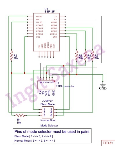
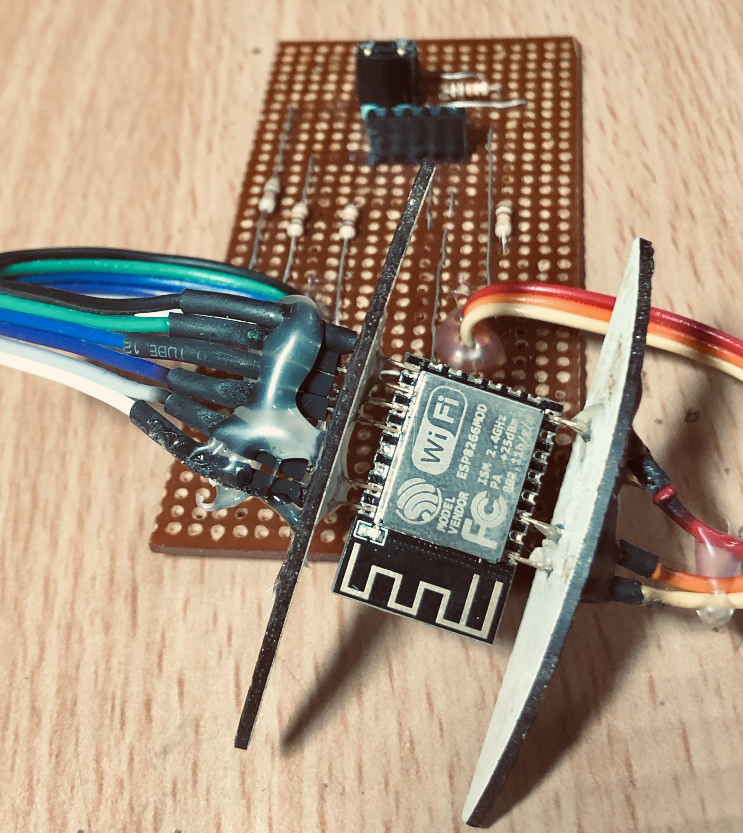
This circuit diagram can be used to boot the ESP in the flash mode or the normal working mode. This is made possible by using the jumper pins (labelled as JUMPER in the schematic). Note that the jumper would need pair of pins to be toggled at the same time. One set of pin helps to toggle the RESET pin and the other one toggles the GPIO0 pin. Refer to the box under the circuit schematic or the description at the end of this paragraph. The connector labelled as "H1 FTDI connector", would be used to setup a 5 pin female header. This header would later allow the FTDI board to sit in. If your FTDI board provides a different pin layout or has a female header on it, then you would need to adapt this circuit schematic accordingly. For jumpers, I soldered male header pins on my perf board and created a jumper out of female headers. (Refer to the pic of the completed project)
Connections for FLASH mode:
- RST pin to be connected to CTS of FTDI board
- GPIO0 to be pulled low via 10k resistor
Connections for Normal working mode
- RST pin to be pulled high via 10k resistor
- GPIO0 to be pulled high via 10k resistor
Note: high here implies a suppy voltage of 3.3v DC
Mica Sheets
I started off with this wooden mica sheet. These are orignally used to cover the electrical junction boxes on walls. In India, these can be bought from any electrical's shop.
Slicing the Mica Sheets
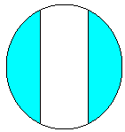
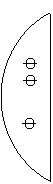
Cut the sheets as shown in the image above. We will be using the Cyan coloured portion further.
Drilling Holes in the MICA
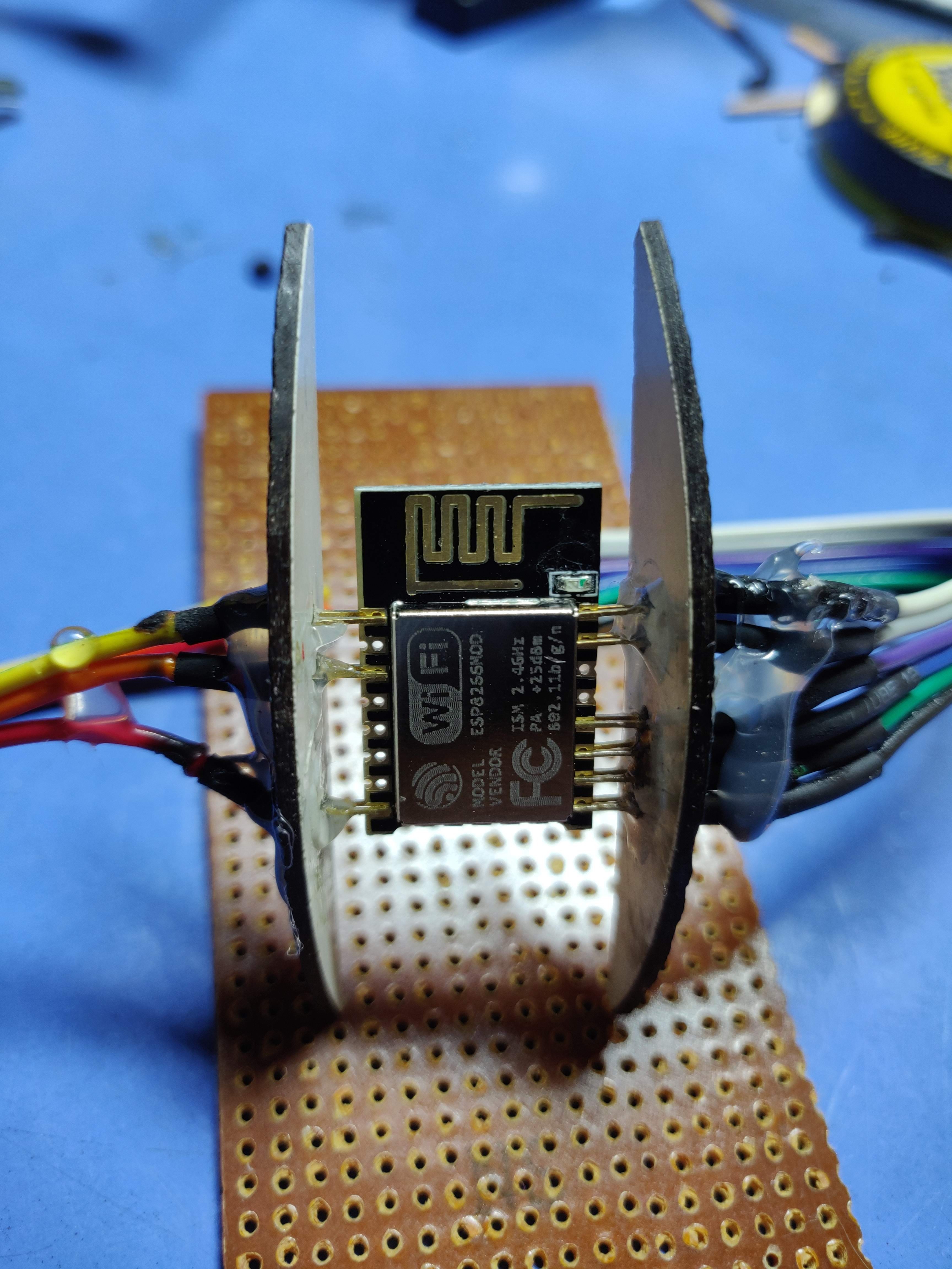
Now, as you can see in the schematic, there are 3 and 6 connectors of ESP at each side, that needs to be connected. So use ESP module itself as a guide to determine the spacing between the holes. It is crucial to use small diameter nails so that the holes do not get into each other. I used these nails to make through holes in the mica sheet (Read the subsequent steps to get an idea of the hole diameter). Then I used a screw driver to make a small indentations along the hole diameter. These indentations would later hold the metallic connectors in place. Refer the figure above and also the picture of the finished product to get the idea.
Prepare the Connectors
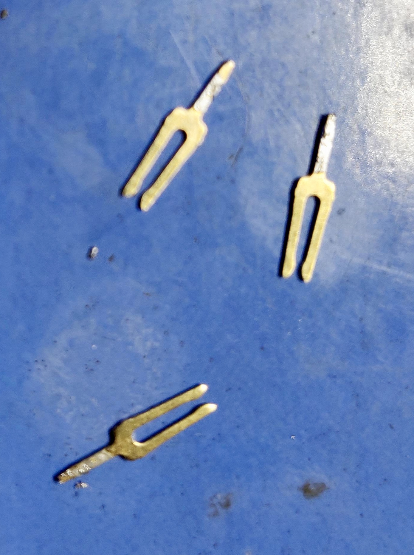
I used the connectors from the female headers. I broke the plastic covering to expose the connector. The open end of these connector would just slide over the ESP12F terminals and would provide a very good connection due to its spring action. The notch of these connector would go into the holes that were cut in the mic sheet. The diameter of the holes must be sufficient to just let the notch of the connector to get thru, while the shoulder of the connectr must rest in the indentations that were made along the holes in the sheet.
Assembling the ESP Holder
- Slide the connector terminals on ESP and use it as a guide to slide the connectors into the MICA sheet. The connectors should sit in the indentations made earlier. Slide the connectors until its shoulders starts to touch the mica sheet. Resize holes if needed.
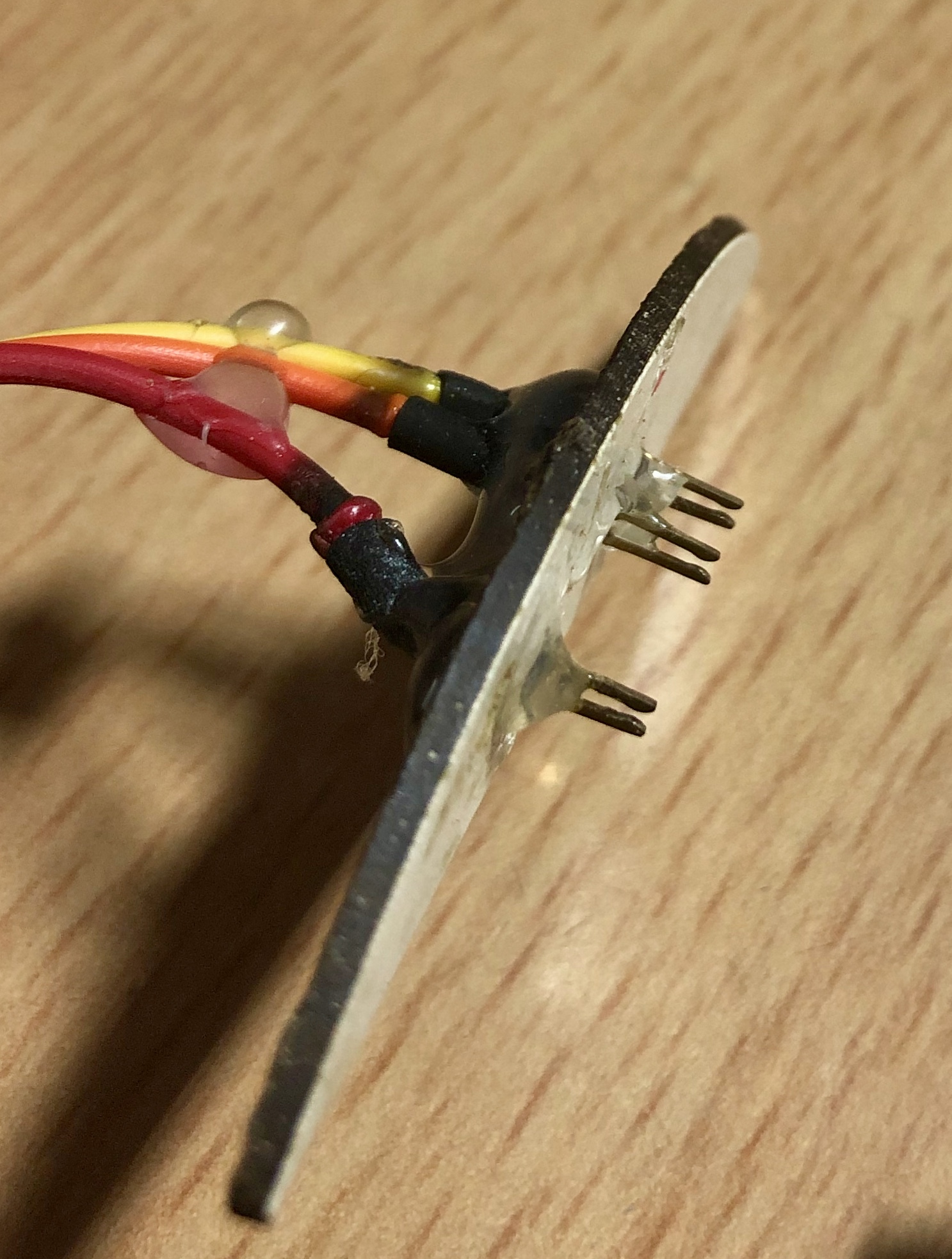
- Once in place, use some hot glue to let these connectors sit in place firmly. The hot glue must be used at the shoulder end of the mica-connector (the end visible in the pic above). The other side of the connector would be used to solder wires. Using hot glue at that end (at this point) would mess up the things.
- Solder wires to the other end. Using heat shink tubes is preferred [I burnt mine, pardon me for that :( ]
- Now use hot glue at this end so that the entire arrangment gets a good mechanical stability.
- Repeat the same for the other end too. Refer the image of the finished project for reference.
Finishing It Up
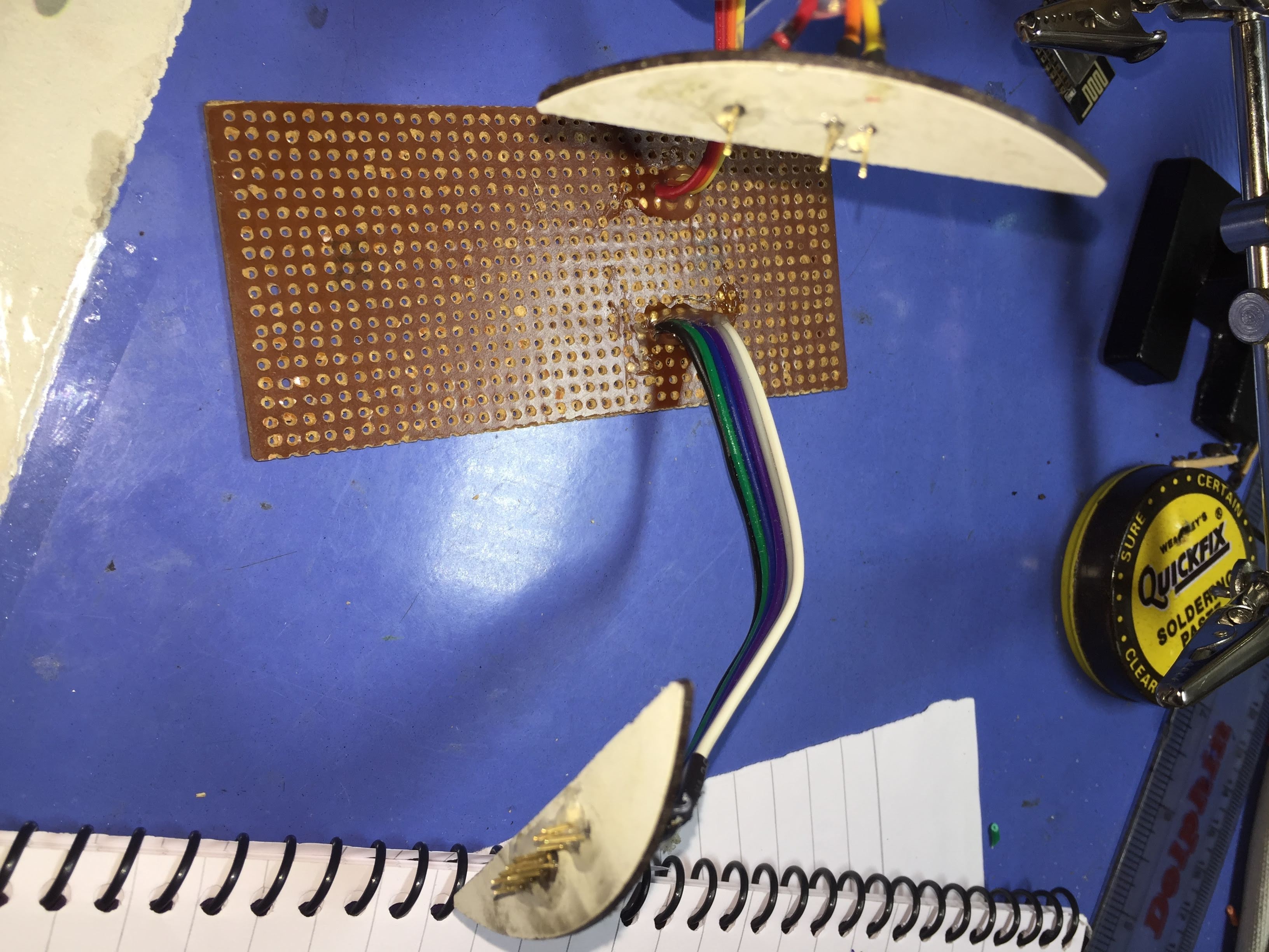
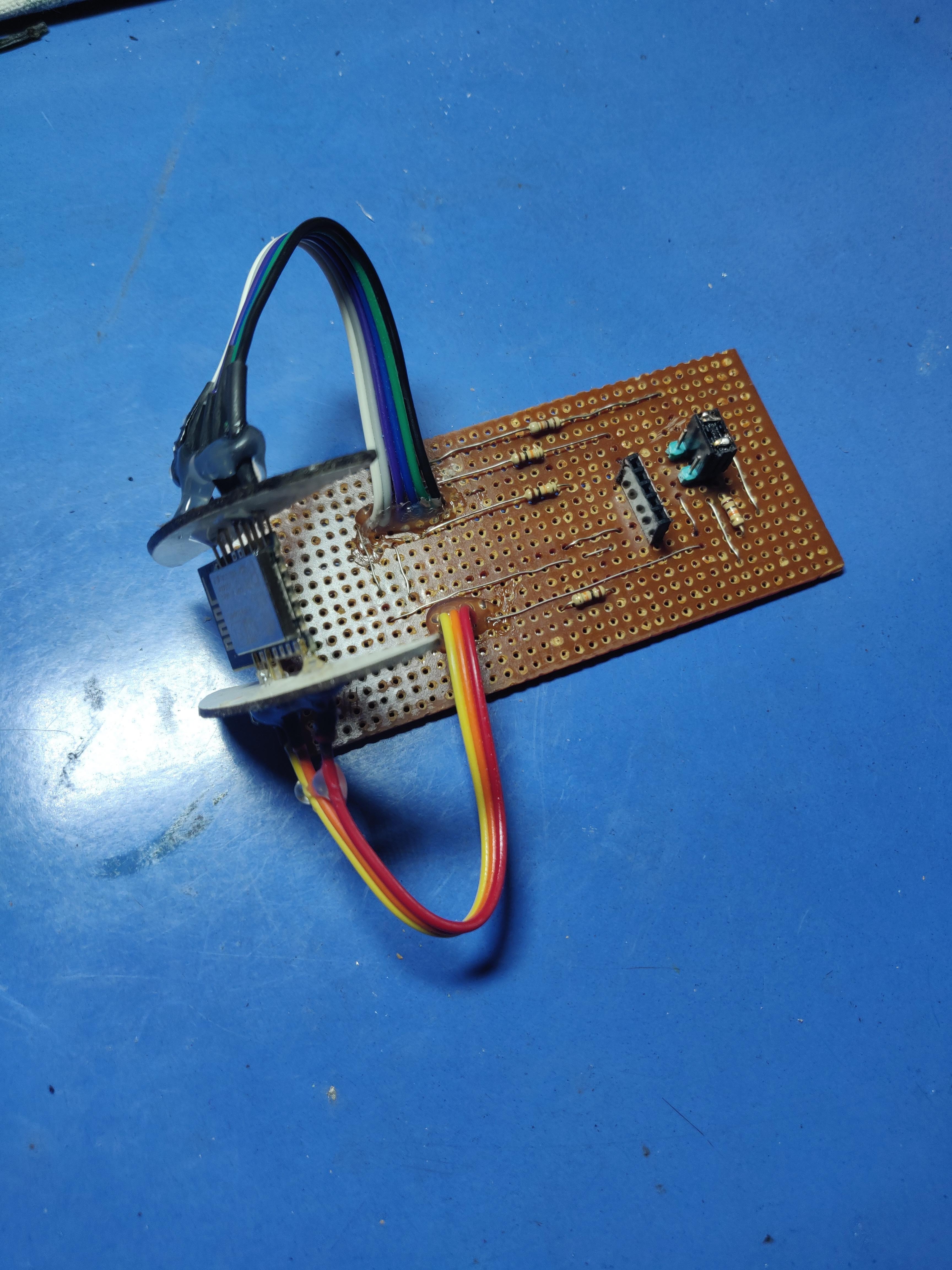
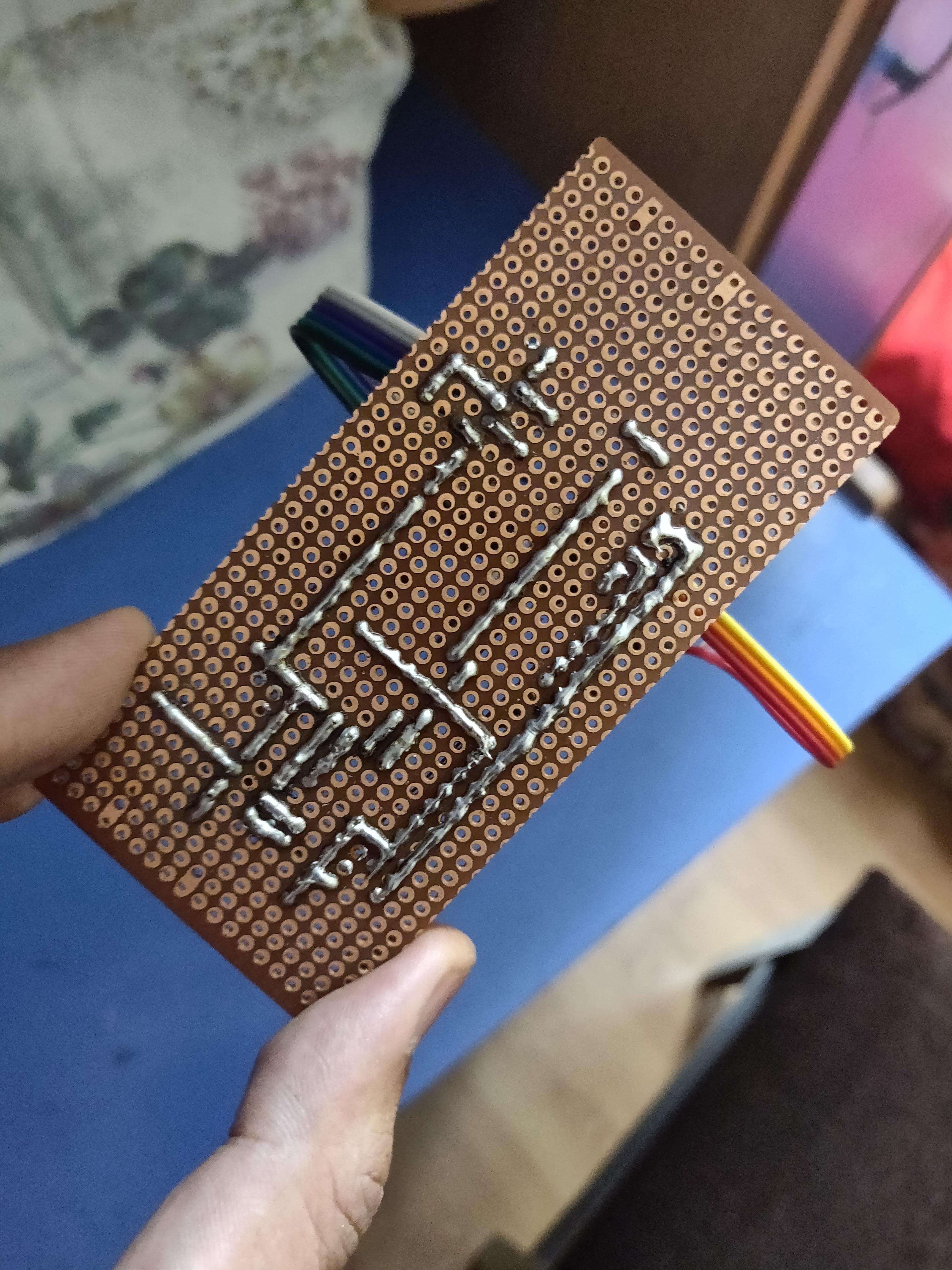
- Make the connections on the perf board as per the schematic.
- Solder the wires coming from the ESP holder on to the PCB
- Use some hot glue to give these connections a good mechanical stability.
- Now slide the holder terminals on to ESP as per the schematic.
- Insert the FTDI board on the female headers
- Throw the jumper in the "Flash position" and upload the blink sketch.
The Blink Sketch!
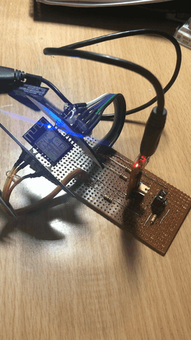
The blink sketch was uploaded and it worked!
To upload, open Arduino IDE, Select "ESP8266 Generic Module" as the board, open the blink sketch from the ESP8266 examples and upload.
As a last note, I built this project in November 2018 and it is working flwalessly for me since then! So, its very much reliable.
I normally would use nodeMCU for programming, but when it comes to building a final working project, I use this DIY programmer to program the ESP12F and then solder it on to my custom PCB.
Hope you liked it! Goodbye!