DIY CNC Machine


CNC or, computerized numerical controll machines make many of the parts on vehicles and products that we use today. For this reason I decided to build one of my own to make my own metal and wood parts. Hello my name is Henry Tacha, I am 13 years old and in 9th grade. I created this project through my STEM class at Tacha Academy. I entirely printed and designed from scratch the machine that you see, last winter. I am excited to show you how I designed and built this machine.
Supplies
- PLA 1KG
- 4 16 mm linear bearings
- 8 8mm bearings
- 2 400mm linear rods
- 2 16mm linear rods
- 6 8 mm 2mm pitch lead screw nuts
- 1 400mm 2 mm pitch lead screw
- 1 300mm 2 mm pitch lead screw
- 2 165mm linear rods
- 1 165mm 2mm pitch threaded rod
- 3 nema 17 2 amp stepper motors
- 1 arduino uno
- 1 arduino cnc shield v3
- 3 dvr8825 drivers
- 1 500w spindle motor with power supply here
- 2mm screws
- 3mm screws
- 4mm screws
- 5mm screws
- 1 12 by 12 inch aluminum plate
- metal L corner, L side, and T side brackets
- 24 volt at least 10 amp power supply
What Is a CNC Machine and How Does It Work

A CNC machine, computerized numerical control machine, is a router controlled by a micro controller that interfaces to a main computer. Which uploads movement commands, or G-code, to the micro controller. The micro controller moves a stepper motor, with a stepper driver, that intern moves a axis or plane of the CNC machine. A stepper motor is a type of motor capable of precise moments bases on its ability to step. However, because of these ability's, the motor is a 4 pin ac motor. Meaning it has to have a driver circuit in order to covert digital pulses to motor positions. In most CNC machines there are 3 axis; x, y, and z or zed axis. These move left and right, back and forward, or up and down. The type of software that the computer sends to the microprocessor is called G-code and it is an array of motor positions and instructions for movements. This is the basic idea of what a CNC machine is. Now we can begin the process of building one.
Building the Electric Controller

The first step, I chose was to create and design the electronics that move and control the machine. The system works with an Arduino Uno with a CNC shield controller, and drivers to move the stepper motors. The firmware I chose to run on the machines micro controller is GRBL, a open source CNC control platform. GRBL can also be controlled with universal G-code sender on the main computer. The wiring is very self explanatory as you will see on the CNC shield the X connector goes to X motor and so on with Y and Z motors. I added a E-stop to the circuit for emergency's. the motor power is toggled through a relay controlled by a switch. The AC power for the 24v power supply and the motor power supply are in parallel with one and other. One last thing to keep in mind is that if you choose to use a 24v power supply as I did you will need to set the current limit on the motor drivers.
Downloads
Designing the Machine
To begin, I looked at other machines on the market to see how they worked and what their flaws and benefits where. Next, I began to draw very crude designs on how I wanted my machine to work and look. I settled on a thread screw and linear rod driven design. I then began to start designing my machine through fusion 360. The motor I used was a 500 watt spindle with ER11 collet. Then I decided to use 8 mm rods and 8 mm threaded rods for the y and z axis, and 16 mm rods, and 8 mm threaded rods for the x axis. The brackets I used initially were 3d printed, however, I upgraded to metal brackets later on.
Assemble the Frame
 5_31_2023 7_35_34 PM.png)
 5_31_2023 7_35_42 PM.png)
 5_31_2023 7_35_54 PM.png)
The frame I chose to make was made out of 20 x 20 mm extrusion. Assemble as shown in the image. The measurements are five 400 mm, two 250 mm.
Assemble the Z Axis
 5_31_2023 7_40_42 PM.png)
 5_31_2023 7_40_48 PM.png)
 5_31_2023 7_40_54 PM.png)
 5_31_2023 7_41_02 PM.png)
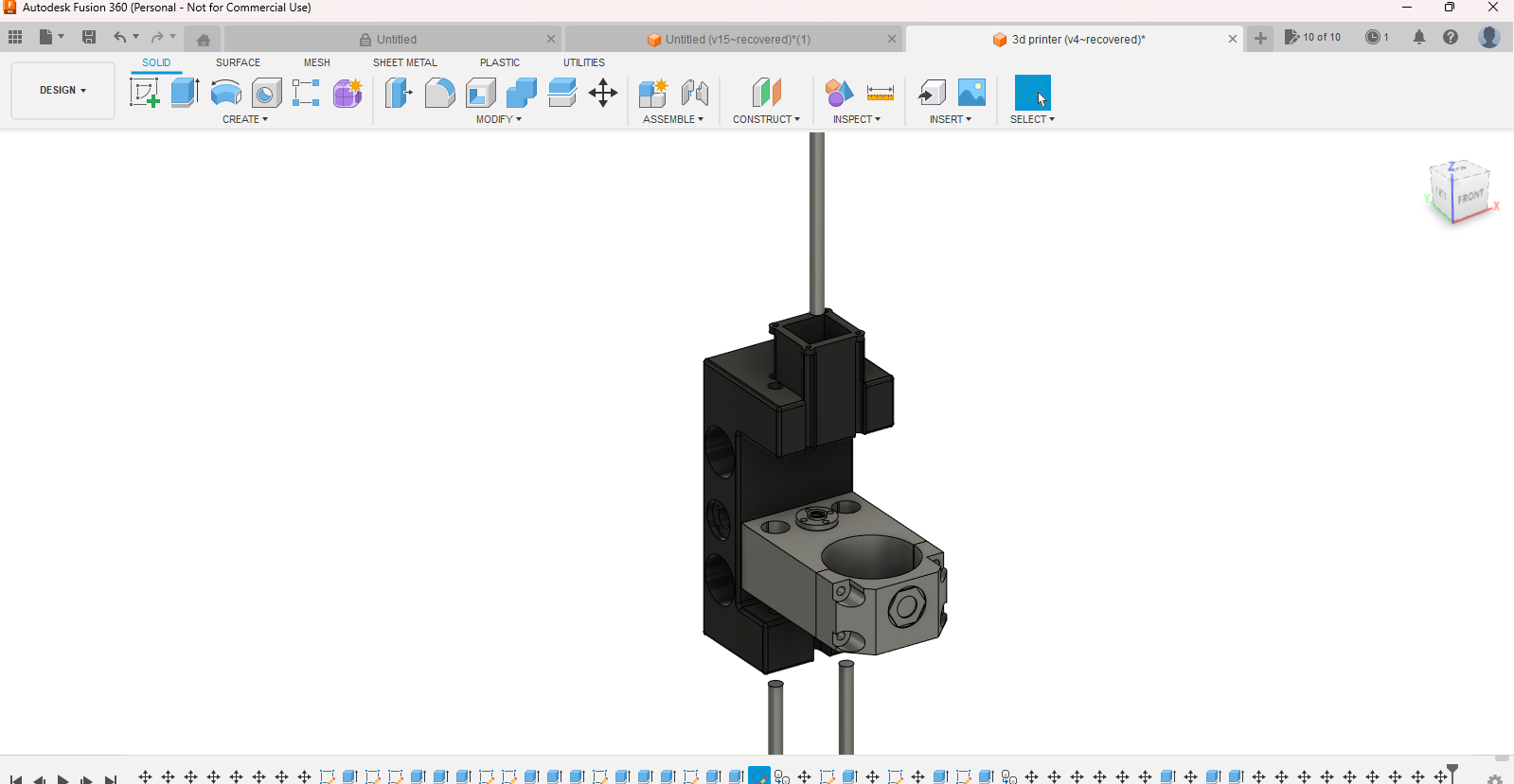
The next step is the Z axis it is make up of two 165 mm rods, and a 165mm threaded rod, 4 linear bearing that are held along with 2 threaded nuts in the motor holder. The two linear rods are preferably tapped into the Z axis C shaped holder. This should be the last step where the motor and threaded rod are already attached to the motor holder. The motor cap is then screwed into the motor holder to hold the motor inside. Cad images are attached.
Assemble the Y Axis
 5_31_2023 7_43_48 PM.png)
 5_31_2023 7_43_53 PM.png)
 5_31_2023 7_44_22 PM.png)
 5_31_2023 7_44_46 PM.png)
 5_31_2023 7_45_05 PM.png)
 5_31_2023 7_45_39 PM.png)
The Y axis is made up of two 400 mm rods, one 300 mm threaded rod, 4 linear bearings, and 2 threaded rod nuts. First, bolt the 4 rod holders onto the frame as shown. Make sure that they are straight or the bed won't ride smoothly. Next, tap the 2 bearings into the bed bearing piece. Then screw the nuts into the bed nut holder. Slide the 2 bearing pieces onto the rods and clip them into the holders, and screw down the tops. You can use the bed stl provided to either print a bed or use it as a temp-let. I will provide cad images of how to assemble the bed.
Assemble the X Axis
 5_31_2023 7_49_21 PM.png)
 5_31_2023 7_49_11 PM.png)
 5_31_2023 7_54_24 PM.png)
 5_31_2023 7_54_44 PM.png)
 5_31_2023 7_54_51 PM.png)
 5_31_2023 7_56_23 PM.png)
 5_31_2023 7_57_10 PM.png)
 5_31_2023 7_57_37 PM.png)
For the X axis slide the two rod holders (one holds the motor, put it on the right) onto the two 250mm extrusion pieces. I Used 5 mm bolts with t nuts to bolt them down. Then attach two threaded nuts to the side of the z axis. Tap the 16mm linear bearing into the z axis. Now thread the 8 mm threaded rod with the motor through the z axis holder. Bolt the motor to the motor holder. Next, slide the linear rods through the z axis. Tap them through the two holders so that they have a tight fit. Finally, attach the x and z top piece to the y bottom piece.
Results


The machine was able to cut metal and wood. At this point I decided to make a dedicated table for this CNC machine that has a hole under the machine with a tub so that coolant can be used. I also added 3 slide-in walls that keeps sawdust off the floor, and side of the table where my computer sits. Also for speeds and feeds, I used Fusion 360 to generate the tool paths. I used 500 mm a seconds for wood and aluminum. You can cut 2 mm deep on wood and for aluminum 0.3 to 0.5 mm. To conclude, I set out to make this CNC machine with the goal to design and make parts not only out of wood but also metal. I believe that I have succeeded in that goal.