DIY Bench Power Supply


Greetings everyone welcome back, and here's a powerful project, the DIY Bench Power Supply. With the exception of the PSU we used, which was extracted from an old Ender 3 printer, everything was made completely from scratch.
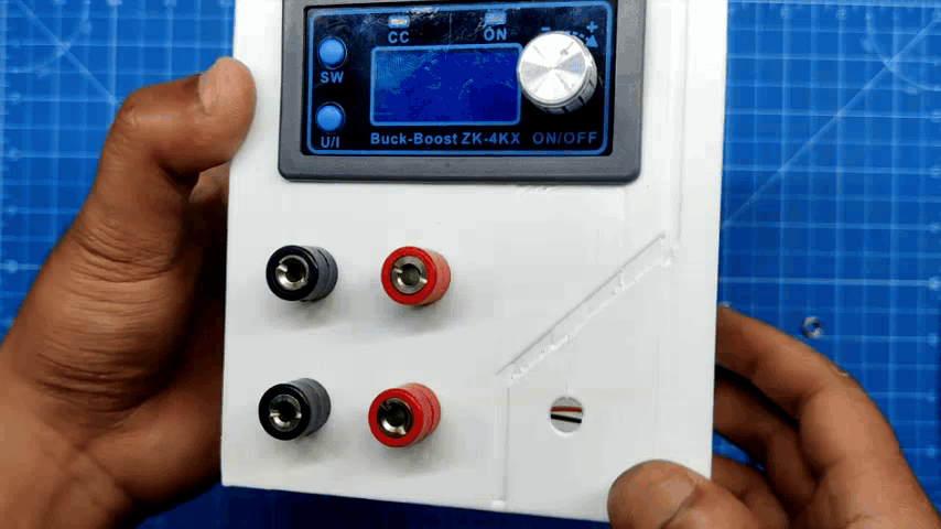
Here, we are using the ZK-4KX DC-DC Buck Boost converter module, an adjustable regulated power supply module with a voltage range of 0.5–30V and 4A. It can be used for a number of power-related applications, such as solar battery charging, as a boost converter to drive high-power LEDs, or even to create a bench power supply.
The ZK-4X is solely a module that requires 0 to 30V to provide us with regulated or boosted voltage and current; therefore, we needed to add a power supply, which we were able to recover from the Ender 3 3D printer. This power supply was a 24V, 10A SMPS.
We created a PCB with a flux capacitor design to add some visual elements to our project. It has a few SMD LEDs that continuously display an animation like a flux capacitor. The Attiny85 microcontroller drives all of the LEDs, and the SMPS 24V power supply powers this PCB.
We added a Power INLET box with a fuse holder, along with a few banana pin connectors and other stuff, which are all clearly explained in this Instructables, so let's get started with the build.
Supplies
These were the materials used in this build.
- Custom PCB (Provided by PCBWAY)
- ZK-4KX DC DC Buck Boost Module
- 24V 10A SMPS
- Attiny85
- Green 0603 Package LEDs
- 10K Resistor 0805 Package
- 8205S Mosfet IC
- ON OFF Switch 6 Pin
- ON OFF Toggle Switch SPDT Knob Type
- Banana Pin Connector, Male and Female
- Power Inlet: 240V 10A
- Resistor 1K 2512 Package
- 7V - 26V DC DC Buck Module 5V Output
ZK-4KX DC-DC Buck Boost Module


The heart of this project is the ZK-4KX DC DC Buck Boost Converter, which is a 0.5–30V 4A Power Module Adjustable Regulated Power Supply featuring an LCD that can display input/output voltage, output current, output power, output capacity/output time, along with many key features like a good conversion efficiency of 88%, stable 3A output current, input and output reverse protection, and more.
Here's its full manual, which you can checkout for more details.
https://manuals.plus/parts-express/zk-4kx-cnc-dc-dc-buck-boost-converter-manual
SPECIFICATIONS-
- Input voltage: 5.0–30 volts
- Output voltage: 0.5–30 volts
- Output current: can work stably at 3A for a long time, and can reach 4A under enhanced heat dissipation
- Output power: natural heat dissipation, 35W; strengthened heat dissipation, 50W
- Voltage display resolution: 0.01V
- Current display resolution: 0.001A
- Conversion efficiency: about 88%
- Soft start: yes (with high power, the load module may fail when starting)
- Protection mechanism:
- Input anti-reverse connection
- Output: anti-reverse irrigation
- Input under voltage protection (4.8–30 V adjustable, default 4.8 V)
- Output overvoltage protection (0.5–31 V adjustable, default 31V)
- Output overcurrent protection 0-4.1a (adjustable, default 4.1A)
- Overpower protection (0-50w adjustable, default 50W)
- Overtemperature protection (80-110°C adjustable, default 110℃)
- Timeout protection (0–100 h adjustable, off by default)
- Super capacity protection (0–60 ah adjustable, off by default)
- Operating frequency: 180 kHz
How to use:
The device operates by providing power to its input terminals; however, in order to turn on the output terminal, we must tap the rotary encoder button.
The output terminal's voltage can be set by using the rotary encoder.
The SET button has two main functions that are as follows: when pressed once, it indicates the amount of Ah utilized, and when pressed twice, it shows the amount of A that the load has used. The third tap changes it back to mA consumed by the load, and the fourth tap displays the W consumed by the load.
The U/I button is used for setting voltage and constant current. It can be seen that a certain digit of the output voltage value is flashing. Rotate the encoder left and right to adjust the major and minor.Short-press the rotary encoder to choose which bit of output voltage to set. After setting, press the U/I button 2 times to return to the normal interface. Or automatically return to the normal interface after stopping operation for 10 seconds.
Downloads
Power Supply


We are using an old 3D printer's (Ender 3) 24V/10A power supply, which powers 24V servo motors, as our power source. Given that the ZK-4KX Module only allows voltage up to 30V, a 24V PSU was ideal for this situation.
More specifically, this supply was manufactured by Chengliang; it is a 360W 24V PSU with a maximum output current of 15A, but I was only able to extract a maximum of 10A at 24V from it. However, it works flawlessly as a PSU for our project.
It even has an integrated fan to cool the PSU's internal components.
In addition to the PSU, we also removed the power inlet from ender 3, which we would utilize as the PSU's inlet for the bench power supply project.
DESIGN


The primary body of the bench power supply is composed of three main sections that are connected to create a single, cohesive body.
The ZK-4KX Converter Module and four female banana pin sockets are added to the Output section, which also has a switch knob on the front side.
Then there's the Power In Section which houses the Power INLET Socket.
Also, connected between the output side part and power in part, we have a Middle section that connects both parts together.
A few mounting ribs are used inside the output section and power in section to hold the PSU in place after it is added to the setup.
In addition, a custom PCB has been added to the front faces of the Middle and Power IN sections. On this PCB, LEDs will be placed to create an aesthetically pleasing light board that is modeled after a flux capacitor.
The models were created using Fusion360, and three different PLA colors—white, grey, and black—were used to 3D print them.
Flux Capacitor


The Flux Capacitor Circuit was designed first with one major change from the original project I made a couple of years ago: we added five loads instead of the original four LED loads.
In order to power three parallel LEDs, we have added five N-channel Mosfets (8205S) in this case. The I/O pins of the Attiny85 are connected to the gate of each mosfet through a resistor.
The device is turned on or off via a push switch that is connected to the VCC. To further limit the current flowing to the LEDs, we have included a load resistor in this case. A 1K resistor is being utilized in a package of 2512.
This circuit was actually from an old, similar project, which you can checkout here:
https://www.instructables.com/Flux-Capacitor-PCB-Badge-V3/
As for the PCB outline, we use the layout made in the Cad file to make the board outline and position the mounting holes.
The PCB was then designed, and each component was placed on the board. LEDs were placed in a Y shape, resembling the flux capacitor.
PCBWAY


After completing the PCB design, we export the Gerber data and send it to PCBWAY for samples.
We placed an order for a white silkscreen LED board.
After placing the order, the PCBs were received within a week, and the PCB quality was pretty great.
They are presently celebrating their tenth anniversary in business by hosting a tour that includes a few activities in which you can take part and win some goodies, such as special coupons and the chance to open blind boxes filled with merchandise from their gift shop.
Over the past ten years, PCBWay has distinguished itself by providing outstanding PCB manufacturing and assembly services, becoming a trusted partner for countless engineers and designers worldwide.
Their commitment to quality and customer satisfaction has been unwavering, leading to significant growth and expansion.
You guys can check out PCBWAY If you want great PCB service at an affordable rate.
PCB Assembly Process


- The PCB assembly process begins by first adding solder paste to each component pad.
- Next, we pick and organize each SMD component after positioning it in its proper location.
- After that, we set the board on our PCB hotplate reflow hotplate, which increases the PCB's temperature from below to the point at which solder paste melts, allowing the components to be soldered to their pads.
- Next, we placed the Push Switch and DIP8 Socket in their proper locations and used a soldering iron to solder the respective pads.
The board is now complete.
CODE and Flashing Process
This is the basic code that we utilized for this project. Five I/O pins of the Attiny85 (D0, D1, D2, D3, D4) are connected to each of the five outputs that we are using.
This is a chaser sketch that exhibits a wave-like motion where light appears to be moving back and forth by sequentially toggling LEDs one after another.
int pinsCount=5;                        // declaring the integer variable pinsCount
int pins[] = {0,1,2,3,4};          // declaring the array pins[]
void setup() {
pinMode(0, OUTPUT);
pinMode(1, OUTPUT);
pinMode(2, OUTPUT);
pinMode(3, OUTPUT);
pinMode(4, OUTPUT);
}
void loop() {
for (int i=0; i<pinsCount; i=i+1){    // chasing right
digitalWrite(pins[i], HIGH);         // switching the LED at index i on
delay(70);                          // stopping the program for 100 milliseconds
digitalWrite(pins[i], LOW);          // switching the LED at index i off
}
for (int i=pinsCount-1; i>0; i=i-1){   // chasing left (except the outer leds)
digitalWrite(pins[i], HIGH);         // switching the LED at index i on
delay(70);                          // stopping the program for 100 milliseconds
digitalWrite(pins[i], LOW);          // switching the LED at index i off
}
}
Flashing Process
Here, we first install the Attiy85 on the DIP8 Socket of the shield. (Note that the Arduino Nano on the ISP Shield has the ISP sketch flashed on it.)
- Next, we install the Attiny85 Core files for Arduino by going to the below link.
https://github.com/SpenceKonde/ATTinyCore
- After installing and setting up the core files, we go to the tool menu and select the Attiny85 on board. We set the B.O.D to 1.8V and selected the programmer as "Arduino as ISP".
- We then burn the bootloader, which takes up to 30 seconds to burn.
- Once the bootloader has been burned, we select "Upload using programmer" from the sketch menu to upload the sketch to the Attiny85. The ISP flashing method does not support the regular upload method.
Power Source for Flux Capacitor Board


We use a DC-DC Buck converter module, which runs at 7–26V and can provide a constant 5V, to power the flux capacitor, a 5V device, from a 24V supply.
Here, we connected the DC DC Buck module's output wires to the VCC and GND of the flux capacitor board after adding wires for the module's input and output using a soldering iron.
Basic Setup


- We added the Power Inlet's Live, neutral, and earth wires to the PSU Live neutral and earth port.
- Next, we use a multimeter to measure the SPMS's output to see if the setup is working or not.
- Next, we attach the input wire of the DC-DC Module to the power supply's GND and 24V + ports. The flux capacitor board is powered in this way.
- We also added the ZK-4KX module's input connections with 24V+ and GND in a similar manner.
- We connected the positive and negative probes of a multimeter to the output connector of the ZK-4KX module in order to measure the output voltage of the ZK-4KX board.
- Both the ZK-4KX and the flux capacitor appear to function when the Power Inlet switch is turned on.
- We turn the ZK-4KX Module's knob and see that the multimeter displays the same reading as what is displayed on the module's screen.
- Now that the setup is working, we can begin the assembly procedure.
Assembly Process: Output Section


- The assembly process began with setting up the output section and inserting the ZK-4KX module into the designated body slot.
- We next insert the female banana pin connector into the four holes on the body and tighten them firmly with the provided M4 nut.
- The banana pin has a washer-like part that we can solder wires to and make connections on. To that end, we connected two washers together by soldering the pads on them. We then added extra wire to link the washer-wire assembly to the ZK-4KX converter module's output terminal.
- We create a total of two washer-wire assemblies, each of which is positioned behind the banana pins that have been inserted to the output section body. The banana pin will be connected to the ZK-4KX Module's positive and negative output terminals via these two washer wire assemblies.
- The toggle switch was then inserted and tightened into the body's designated hole.
- Next, we connected the toggle switch to the ZK-4KX module. This switch is designed to break the positive line that connects the module's input to the power supply.
Assembly Process: Power Input Section


- Starting with the Power Inlet and fastening it with two M3 screws, we now begin the assembly of the Power Input Section.
- Using six m2 screws—three on the bottom and three on the top—we then joined the middle section and the power input section.
- On the front face of the Power Input-middle section assembly part, we then position the flux capacitor PCB in its proper location.
- The flux capacitor PCB is fastened to its location using four M2 screws.
Final Assembly


- The live neutral and ground wires are connected to the SMPS terminals to initiate the final assembly process, which involves connecting the SMPS to the Power Input section.
- The DC-DC buck module's positive and negative were then connected to the SMPS's +24V and GND terminals. (The flux capacitor PCB is powered by the DC-DC Buck converter.)
- Next, we connected the ZK-4KX's input terminal to the SMPS's 24V + and GND inputs. The wiring is finished now.
- Now, we slide the SMPS into the power input section.
- On the opposite side, we added the output section to the power input section. SMPS is now secured between these two sections.
- Next, we use six M2 screws to attach both sections together.
Assembly is now complete.
Result


The result of this project is this DIY bench power supply that was put together from scratch using a few components. Here, we used a 3D printer's salvaged SMPS to power both the flux capacitor circuit and the ZK-4KX module.
In order to test this setup, we operate a 12V Gear DC motor by connecting the motor's power terminals using the banana pin that is attached to an alligator clip.
In the same way, we powered on our previous LED badge project, which utilized 3.4 volts. This device's low 50 mA consumption was shown on the ZK-4KX display.
The ZK-4KX Module can be used to drive a variety of loads with constant current or voltage while monitoring a number of parameters, such as power consumption, power, current, and temperature—all of which are quite helpful.
We are utilizing the ZK-4KX BUCK BOOST Module here, but the DPS3003, a well-liked substitute with a colored display and smart interface that is more user-friendly and offers more readings and a few other capabilities, is a similar buck boost module. Since the two modules are the same size, someone with a somewhat larger budget can simply replace the ZK-4KX with a DPS30003.
This bench power supply should last at least five or six years, but we will have to wait and see.
Overall, this project was a success and needs no further revisions.
Thanks for reaching this far and i will be back with a new project pretty soon.
Peace.