DIY Backlit Keyboard: Convert Non Backlit Keyboard Into a Backlit Keyboard
13196 Views, 2 Favorites, 0 Comments
DIY Backlit Keyboard: Convert Non Backlit Keyboard Into a Backlit Keyboard


This is my first Instructable and I'm not good at taking good shots so please bear with me.
Are you a night owl? Do you stay late at night to do some Word documents? Or you're a gamer and you have your newly installed game and still learning its controls, but only to find out that it is too hard to see your keyboard at night. Thankfully, the backlit keyboard does exist but reliable ones do not come in cheap, and some cheap ones are just Chinese knockoffs that would only last for a few thousand key press. Fear not, in this Instructable tutorial, you will surely learn how to convert your old boring non-backlit keyboard to a cool backlit keyboard which would make your life easier when typing in the dark.
Before we begin, you must have some prior knowledge and experience in electronics, as we are gonna be dealing with a lot of soldering and electrical work.
I recommend you to read this Instructable about soldering (if you are new) before we begin:
Don't worry, we are not gonna be soldering the tiniest of the tiny SMD packages.
It took me a few days before finishing this project because setting up the camera and the scene consumes lots of time, but you are not gonna record it right? So maybe a good 2-4 hours? I used a screwdriver and screw to make holes on the plastic.
It is also recommended that you've opened your keyboard before, because keyboard design may vary per manufacturer and have planned where you run wires and etc.
Supplies
If you live in the Philippines, then these links are for you :)
If not, there should be probably an eBay or Amazon alternative for that
Materials:
1. 5M LED Strip (Any colors you prefer)(why 5m? better to be safe than sorry)
Link: Shopee
2.Soldering lead (I consumed 1.5 meters of soldering lead in this project)
Link: Shopee
3.Potentiometer (50kΩ-100kΩ) (For dimming)
Link: Shopee
4.20-25 AWG wires *Nothing more or nothing less, smaller AWG would make typing hard and visible on the outside, and bigger AWG would make those wires warm or even on fire
Link: Shopee (22 AWG)
5. Project case: 60 x 36 x 25mm/2.4"x 1.4"x 1"(L x W x H)
Link: Shopee
6. Boost converter (MT3608)
Link: Shopee
7. Slide switch
Link: Shopee
8.Potentiometer knob (Optional)
Link: Shopee
9.Your keyboard
Tools and equipment:
1.Soldering iron
2. De-soldering pump
3.Multimeter
4. Screwdriver
5. Screw (For making holes, may sound hilarious but it works!)
6. Drill (If you don't prefer using a screw)
7. Pliers
8. Wire strippers (Optional, I can strip 22AWG wires with my bare hands)
9.Scissors (You'll find out later why)
10. Tweezers (It would be hard to do this project without tweezers)
Wait, I Can Explain
.png)
.png)
.png)
.png)
.png)
Potentiometer:
Why potentiometer? I know there is PWM, but it is made for high-power LED strips and it requires lots of components. The LEDs I will be using won't consume lots of power and using a 555 timer IC to dim the LED would take a lot of space in the project box, I want to keep the controller box small as possible and without having the need to buy more components.
Boost converter:
The boost converter I will use is an MT3608 module. You can use any other module such as the SX1308 or the CKCS BS01. Make sure to set the boost converter to 9V-11V before soldering together.
Why 9V on a 12V strip?
- Applying a lower voltage on an LED strip would underdrive it. Underdriving it would reduce the current draw and produce less to no heat on the LEDs and the resistors giving it a longer lifespan.
Won't be the lumen output be affected?
- Yes, it does, but barely noticeable unless you apply something lower than 9V it will. You won't need the brightest lumen for backlighting and would just waste more power.
Slide switch, project case, potentiometer knob:
It's self-explanatory
LED strips:
The LED strip I bought is a single-color strip. It is up to you if you want RGB or use different colors of the strip. Wiring it in RGB would be difficult since you would need 3 to 4 wires to solder individually and you have to use a controller board for the strip removing the need for a potentiometer.
The 22 AWG wires:
You are free to use any wire gauge, I recommend somewhere around 22-25 AWG because they are small. Don't use high AWG wires, since they might heat up or add up a resistance causing the strip to be dimmer. Don't use small AWG wires, not only they are big but could also affect typing performance and can be seen from the outside affecting the output.
Planning
.png)
.png)
Not all keyboards are made equal, they all have different shapes and sizes, therefore it is important to first open your keyboard and plan where you will run the wires and how other things will go. I made the planning for weeks and spent countless nights how this would go, but some details weren't followed and made a few messy details.
On the electrical side, it is required for you to follow the USB standards, as we are gonna be powering the LED strip directly from the +5V rail of the USB keyboard. It is better to identify the length of the LED strips that will be used (In my case 2 meters) and put an ammeter connected in series with the boost converter.
My multimeter showed that the boost converter was drawing 530mA from the USB port @ 12V. USB 2 limits it to only 500mA, so I planned to plug it instead into a USB 3 port that can supply the requested current, but according to my research communication is needed with the host to supply the requested 530mA. Now I felt God isn't on my side, but this idea popped into my head, what if I set the boost converter to 9V instead of 12V on a 12V led strip, will it draw less current?
Using the scientific method, I began by questioning myself, will it draw less current?
So I did some research and suggested that it made the current draw significantly lower
After researching, I constructed a hypothesis that lesser voltage means lesser current for LEDs
I tested the hypothesis and analyzed the results
My conclusion was IT'S A YES! I was able to reduce the 530mA to 230mA which the USB 2 standard can supply but to be on the safe side, I will still plug this keyboard on the USB 3 port. Underdriving the LEDs also made its temperature low.
Now that everything is planned, we can now proceed to the next step
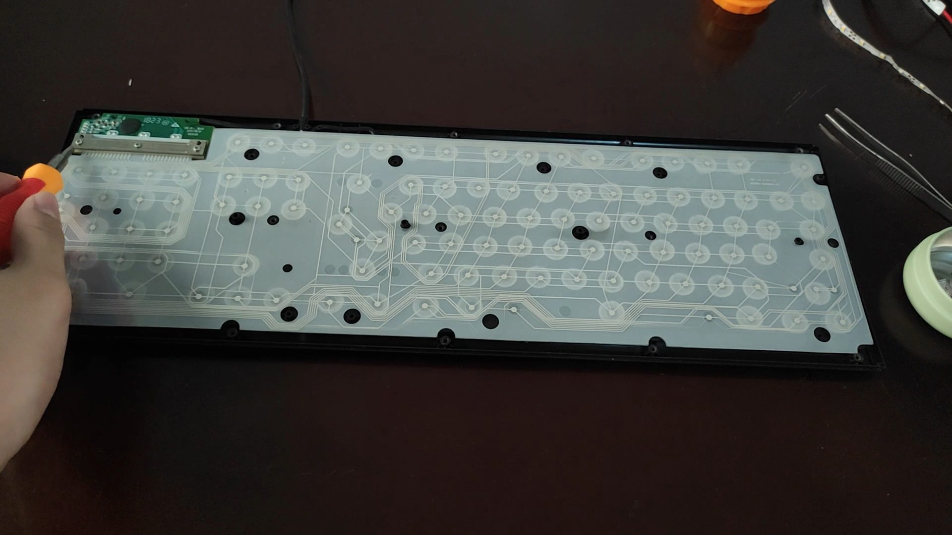
Unscrewing the Back Panel
.png)
.png)
.png)
.png)
.png)
.png)
.png)
.png)
Begin by removing the screw on the back panel which will give you a clear visual of the insides of the keyboard. Begin by separating the keyboard control module and the flexible PCB shown in the picture. After separating both, you are left with the USB wires and the control module itself. Disconnect the JST connector connected to the module which will require a bit of force. Strip the red and black insulation using the soldering iron in order to strip the wire in the middle. If your keyboard has two black wires, you can strip any of those since both of them are just shorted with one being the OTG and one for the actual GND, it won't affect if you strip the OTG or the GND wire. Having the copper strands exposed, perform a Y-splice on both of the wires, it is recommended to use wire color coding in order to identify the polarity of wires. Red is usually positive and black usually negative. Using a multimeter set on a DC voltage range of 20V, connect the red probe to the end of the red wire you have spliced with the USB cable of the keyboard and the black probe on the other. You should get a reading of 4.9V to 5V.
Holes Holes Holes
.png)
.png)
.png)
Start by making a hole on the back of the keyboard shown in the picture. These holes must be able to let a wire in and out of the keyboard. With a screwdriver and a screw, I started manually drilling the plastic on the back of the keyboard and was able to make at least two holes. Using scissors or a cutter, you can make it larger by scraping or carving off any plastic remaining in order for the wires to fit.
Now that you're done on the keyboard side, do the same on the plastic box side, using the method I was able to fit the 22 gauge wires on the box.
After that, strip the insulation of the wires on the plastic box end as shown in the pictures.
Fitting the Components on Box
.png)
.png)
.png)
.png)
.png)
I opened the plastic box and started by soldering the boost converter module to the two wires we previously strip, with the red wire goes to VIN+ and the black goes to VIN-.
Using a flathead screwdriver and a multimeter, I set the boost converter to 9V using an onboard potentiometer and the multimeter probes on the OUT+ and OUT- to set the correct voltage.
Soldering the components on the plastic box will be the hardest part of this project, but with the help of the tweezers, we can get the job done.
With the plastic box cover removed, we can use a ruler or a caliper to plan where to mount the components.
After making a few measurements, I used my pencil to mark the place to put my components.
Using my screwdriver and screw, I started by making a room for the potentiometer, and the switch thereafter.
The switch was the hardest part to deal with, I had to sacrifice blood, sweat, and tears literally on that one just to make a rectangular cutout on the plastic cover.
But in the end, my hard work paid off but this project is still far to an end
Soldering on the Box
.png)
.png)
.png)
.png)
.png)
.png)
.png)
.png)

This is the second hardest step, with the plastic box being too small, I started to tin the leads of the switch and the potentiometer knob shown in the picture. My soldering was a nightmare, seeing my soldering quality gives me anxiety but I can't do anything about it anymore.
It is recommended to use a multimeter to identify the correct leads or pinout of the components, as the switch and the potentiometer have 3 leads, which 2 of them will only be used. Use the continuity tester of your multimeter on the switch, and the resistance on the potentiometer and test if it varies if you spin it.
It is recommended to add a blob of solder on the leads so when you started soldering them together, you would just melt the solder, and using a tweezer, you can position the wire easier.
Be mindful of short circuits!
Do not do this alone, you would need someone to hold the tweezer for you to solder the wires, or else you would just end up soldering nothing.
Make sure you have already set the boost converter output to somewhere around 9V-11V
Setting to 9V is the best thing to do
After finishing soldering the components on the box, it is time to run wires on the output of the potentiometer and the boost converter to the keyboard. Do this by running a wire on the second hole you just recently made and solder the red wire on the other potentiometer lead, and the black wire directly on the negative terminal of the boost converter.
Run the wires inside the keyboard and bring back the cover of the plastic box
Keyboard Side


After running wires on the keyboard, you should have already planned where to put the first sets of LED strips. I planned to put the first row of the strips on the NUMPAD section since this was the nearest place to the plastic box. Remove all of the keycaps on the NUMPAD by using a flathead screwdriver and lifting it up as shown on the pictures, then clean this section with a brush to remove dust and any residue as this would stick on the 3M tape.
Drill a hole on the upper left part of the NUMPAD section and cut the LED strip depending on the size needed then run the LED strip wires on the previously created hole. Splice the previous wire with the wire from the output of the potentiometer, and solder together to make a reliable connection.
Test the circuit by plugging the keyboard from a USB port, it should light up and nothing should produce magic smoke :). Tin the copper pads of the other end of the LED strip and add solder wires on the previously tinned pads. You can now remove the 3M tape included on the back of the LED strip. Cut the same length of the strips and do the exact same procedure.
Keep repeating this till you completely filled the NUMPAD section with lights.
After finishing the entire Numpad section, make way to the arrow section and to the letter row, I don't know how do you call this keyboard parts. Do the same although longer
NOTE:
There are some keyboards that have some metal brackets below their keys, I simply removed all of those to avoid short circuit. In the end, the typing experience should still be the same.
Stick. Solder. Repeat


- Keep repeating the same process on all of the keyboard rows.
- Make sure to clean the surface of the keyboard before sticking the LED strips.
- Some LED strips might not stick well, you can add adhesives like glue gun or epoxy for it to stick.
- When soldering wires, always make sure you have twisted the strands if you are using a stranded wire, this lowers the risk of a short circuit since there are no strands of copper hanging outside the solder blob.
- You can add electrical tape on the joints after soldering for additional protection.
- Put everything back together.
- Lastly, conjoin the box and the keyboard with a glue gun.
Software Side
You can now plug the keyboard on the PC and turn it on
I recommend plugging the keyboard on a USB 3 port because it can provide more current.
But if you don't have a USB 3 port, you can try the USB 2
As I said earlier, this keyboard draws 230mA with the LEDs at full brightness, so mostly you won't have to deal with the software side.
BUT IF IT DOES AFFECTED PERFORMANCE like you experienced lag or slowdowns, try watching the video above. Skip to 13:28 where I will explain why and what you should do in order to avoid lag.
But if you are using macOS or Linux, you are on your own but mostly it shouldn't lag
I'm just doing it to be on the safe side
Can't See the Keyboard?
.png)
.png)
.png)
.png)
.png)
So you are now done with your software side?
Now before you point your finger at me, let me tell you that we are not done yet.
Assuming your keyboard is under something like a desk, get yourself an aluminum tape and stick it underneath it.
It should act as a reflector and would reflect the keycaps giving you a clear look on the keyboard at night.
If your keyboard isn't under something, I know this may seem obscure but use your fingers to reflect it.
Alternatively, you can buy a pudding keycap that would let more light through.
Mistakes That Were Made
Since this is my first time, I gotta admit that I made many mistakes. Here are all the mistakes you must avoid in making this project:
- Should have bought a drill; It would have been easier and made a cleaner job if I had bought a drill in the first place to make cutouts.
- Should have bought a precision knife instead of scissors; I should have bought a precision knife to make carvings and make holes larger.
- Should have bought a rasp to smooth things out; I should have also bought a rasp because I would make a perfect rectangle and smooth uneven cutouts.
- Should have used black wires; I kinda regret it now, should have used a black wire in order to conceal the wires.
- Too much solder blob; I gotta admit that I added so much solder on the LED strip copper pads that it almost made a bridge on the other joint or made a solder spike.
- Pudding keycaps; If you made this mod, you might want to consider buying pudding keycaps, they will make it look better and more light can be seen.
- Should have been more careful in cutting.
Did I Save Money? and Benifits
Oh yes!
The materials cost me $2 assuming that you used the link I listed. Shipping is not included but at least I didn't buy the $20 backlit. My efforts were not in vain as I learned lots of stuff in making this project and I'm looking forward to making more Instructable projects.
Tools and equipment were not included in the $2, so if you don't have the tools and equipment, it might cost you even more but won't be as expensive as the $20 keyboard.
Making this project thought me a lot of things and gave me satisfaction. Seeing my DIY project puts a smile on my face as I spent 272 hours of planning, making, and editing stuff for this Instructable.
At first, this project seemed impossible so I was about to give up. But since I already bought the stuff I need and have already invested time on it. I have nothing else to do but escalate my commitment.
This is a very good learning experience, being a 13-year old this is very satisfying.