DIY BLUETOOTH CONTROL RGB FROM MOBILE(ARDUINO UNO & HC-05 )
by Ohms Lab in Circuits > LEDs
262 Views, 2 Favorites, 0 Comments
DIY BLUETOOTH CONTROL RGB FROM MOBILE(ARDUINO UNO & HC-05 )

Hello world !
In this Instructable, I will tell you how to make bluetooth RGB LED control using Arduino uno which can be control from mobile. This can be used for decorating your house or making a night lamp whose color can set according to your mood. This will be a great tutorial for beginers, So let's start(:
Supplies
To make this project you willl need:
1)Arduino UNO
2)RGB LED (common cathode)
3)HC-05 bluetooth module
4)Breadboard
5)Jumper wires
SOFTWARE
1)Arduino IDE
2)BT_LED_CONTROL(from playstore)
What Is RGB LED??


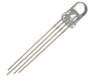
An RGB LED is a combination of 3 LEDs in just one package:
1x Red LED
1x Green LED
1x Blue LED
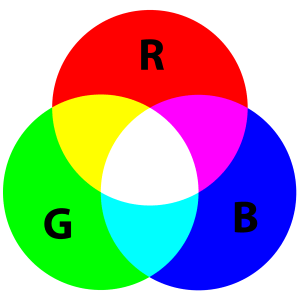
With an RGB LED you can, of course, produce red, green, and blue light, and by configuring the intensity of each LED, you can produce other colors as well.
For example, to produce purely blue light, you’d set the blue LED to the highest intensity and the green and red LEDs to the lowest intensity. For a white light, you’d set all three LEDs to the highest intensity.
To produce other colors, you can combine the three colors in different intensities. To adjust the intensity of each LED you can use a PWM signal.
Because the LEDs are very close to each other, our eyes see the result of the combination of colors, rather than the three colors individually.
---------------------I got this information from this site :
Click this link for more(:
Connection

Connection is very simple.
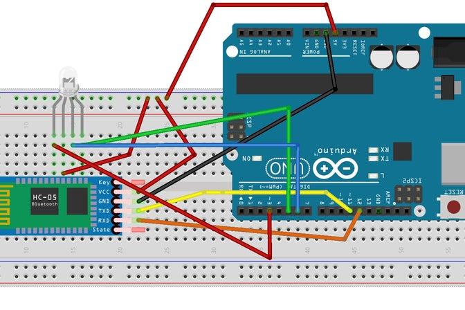
First of all connect bluetooth module HC-05 as usual GND TO GND & VCC to 5V,
TX OF HC-05 TO RX OF UNO &
RX OF HC-05 TO TX OF UNO
Now if you have common cathode RGB led then connect negative terminal(the biggest leg) to GND of arduino.
Now because all other three terminal need different current otherwise they will burn so we will use resistors.
The red terminal will need 100ohm resistor.
The green and blue terminal need 150 ohm resistors to each.
Connect all three terminals according to the schematics I have given above.
RED - 3
GREEN- 5
BLUE - 6
Coding
#include
SoftwareSerial BLU(0,1);
#define redPin 6 #define greenPin 3 #define bluePin 5
void setup() { //Serial setup Serial.begin(9600); Serial.println("-= HC-05 Bluetooth RGB LED =-");
BLU.begin(9600); BLU.println("-= HC-05 Bluetooth RGB LED =-"); pinMode(4, OUTPUT); digitalWrite(4,HIGH);
pinMode(redPin, OUTPUT); pinMode(greenPin, OUTPUT); pinMode(bluePin, OUTPUT);
setColor(255, 0, 0); delay(500); setColor(0, 255, 0); delay(500); setColor(0, 0, 255); delay(500); setColor(255, 255, 255); }
void loop() { while (BLU.available() > 0) { int redInt = BLU.parseInt(); int greenInt = BLU.parseInt(); int blueInt = BLU.parseInt();
redInt = constrain(redInt, 0, 255); greenInt = constrain(greenInt, 0, 255); blueInt = constrain(blueInt, 0, 255);
if (BLU.available() > 0) { setColor(redInt, greenInt, blueInt);
Serial.print("Red: "); Serial.print(redInt); Serial.print(" Green: "); Serial.print(greenInt); Serial.print(" Blue: "); Serial.print(blueInt); Serial.println();
BLU.flush(); } } }
void setColor(int red, int green, int blue) { analogWrite(redPin, red); analogWrite(greenPin, green); analogWrite(bluePin, blue); }
Application & Working

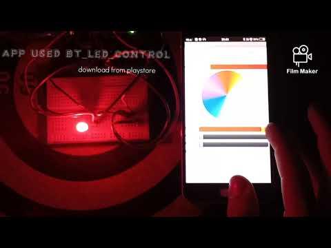
Here I use BT_LED_CONTROL from playstore. It works perfect. You can see my youtube video for more information.
Link: https://youtu.be/_GGFlzvKhlw
Please Subscribe My Youtube Channel!!!
Please subscribe my youtube channel for more " The Invento".
https://youtu.be/_GGFlzvKhlw