DIY Audio Responsive Lighting
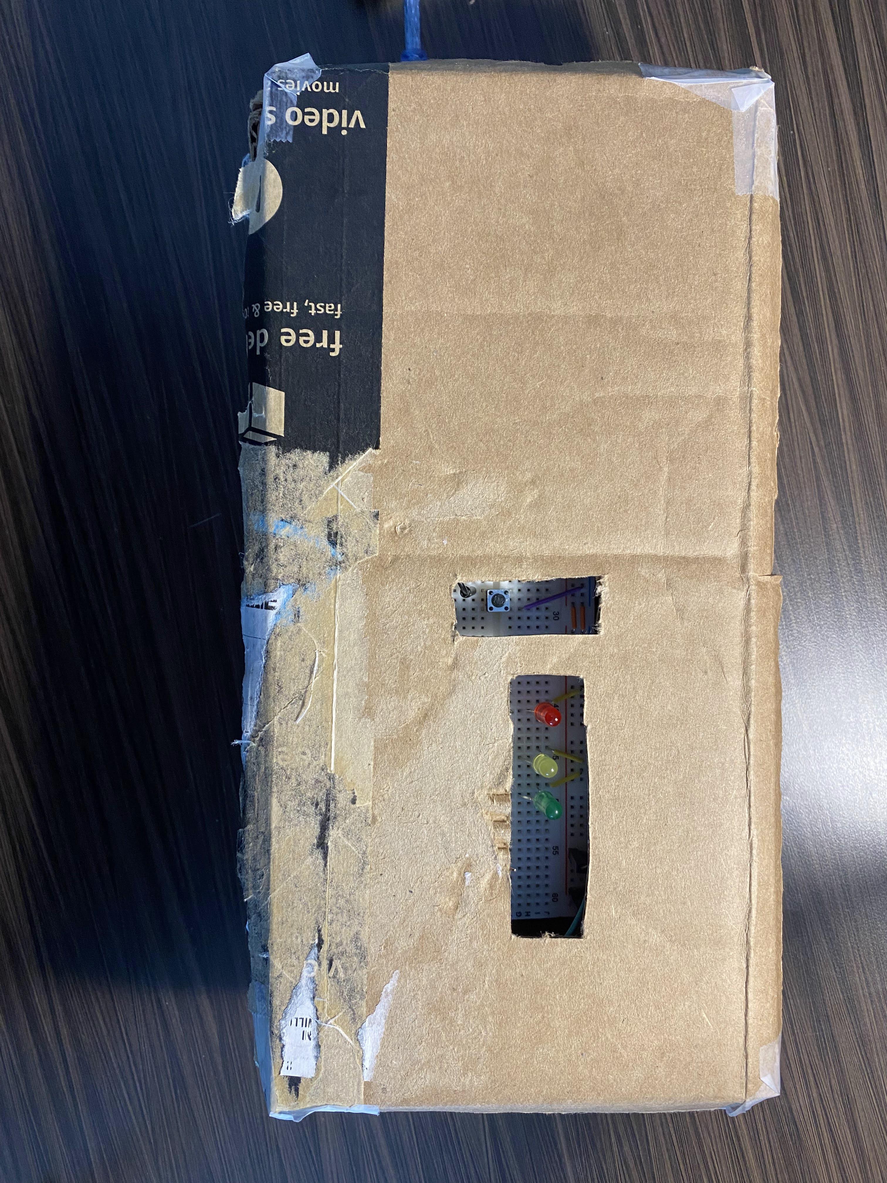
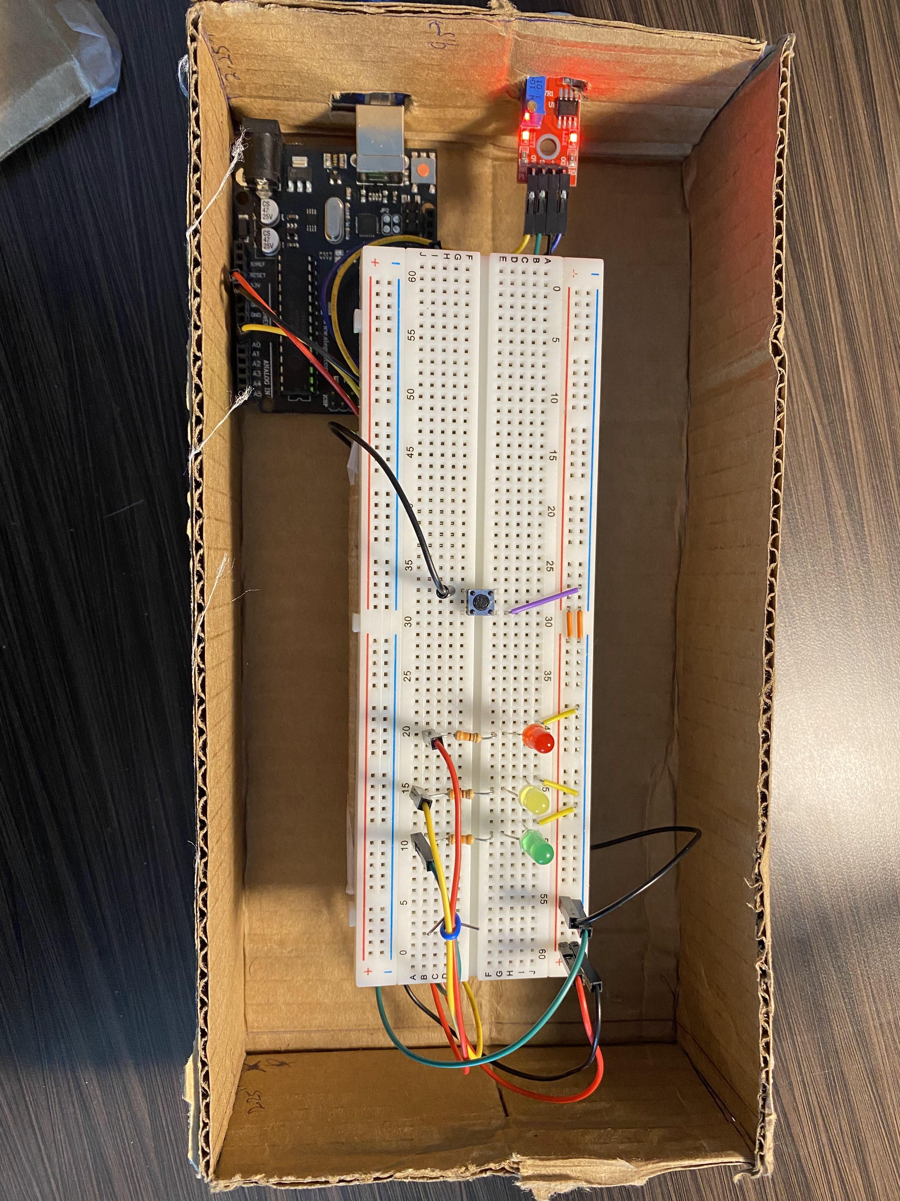
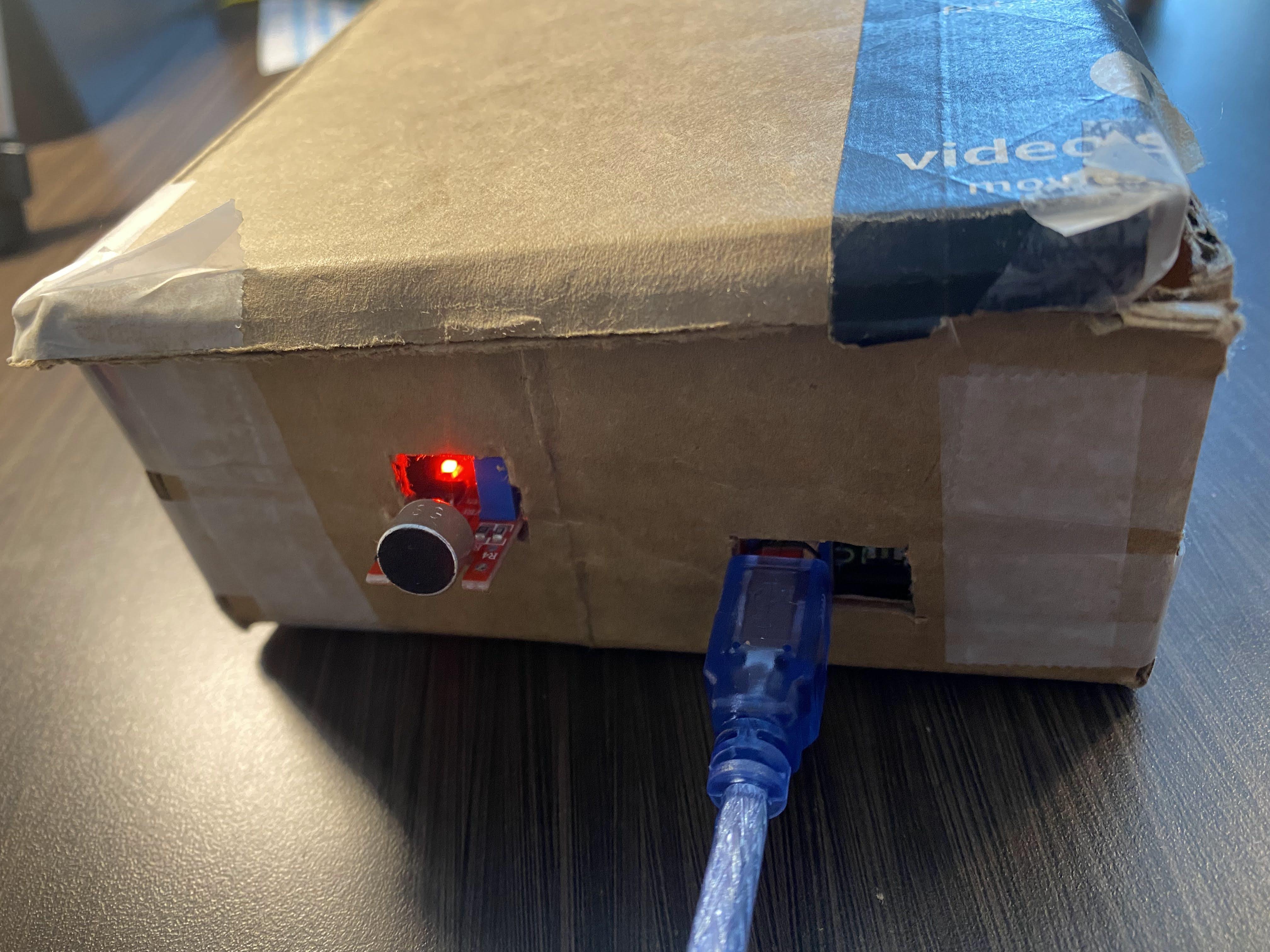
Ever wanted to amp up your music listening experience? The Audio Responsive Lighting is a system that utilizes sound to control the lighting based on the volume of the audio! All you have to do is to place the microphone near the sound source and observe how the lights react to the audio you played!
Supplies
Building the entire system does not require a lot of tools and materials. All you need are the below materials:
Electronics
- Elegoo UNO R3 - https://www.amazon.com/dp/B01EWOE0UU?
- USB Cable (Included in Elegoo UNO R3)
- Breadboard - https://www.ebay.com/itm
- KY-038 Microphone sound sensor - https://hobbyking.com/en_us/keyes
- Tactile push button - https://www.digikey.com/short/4758wqz1
- 5mm LED (red, yellow, green: (1x))
- Red - https://www.sparkfun.com/products/9590
- Yellow - https://www.sparkfun.com/products/9594
- Green - https://www.sparkfun.com/products/9592
- Jumper wires 6" Male-Female (4x) & Male-Male (6x) - https://www.amazon.com/Elegoo-EL-CP-004-Multicolored-Breadboard-arduin
- Small Jumper Wire Kit - https://www.sparkfun.com/products/124
- 330 Ohm Resistors (3x… one for each LED) - https://www.amazon.com/Projects-10EP514330R-330-Resistors-Pack/dp
Tools
- Small Screwdriver (for twisting Potentiometer) - https://www.amazon.com/Screwdriver-SET-Different-Professional-Electronics
- Box Cutter (for cutting cardboard) - https://www.amazon.com/Utility-Cutters-Retractable-Compact-Extended/dp
- Ruler - https://www.amazon.com/Allinone-Plastic-Flexible-inches-Measuring/dp
- Scotch Tape - https://www.amazon.com/Scotch-Applications-Invisible-Engineer
Other materials
- Cardboard (or from around house) - https://www.amazon.com/dp/B079QY6MMX
Software
- Arduino IDE - https://www.arduino.cc/en/software
Wiring Up Components
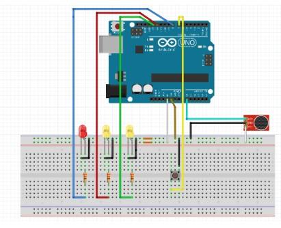
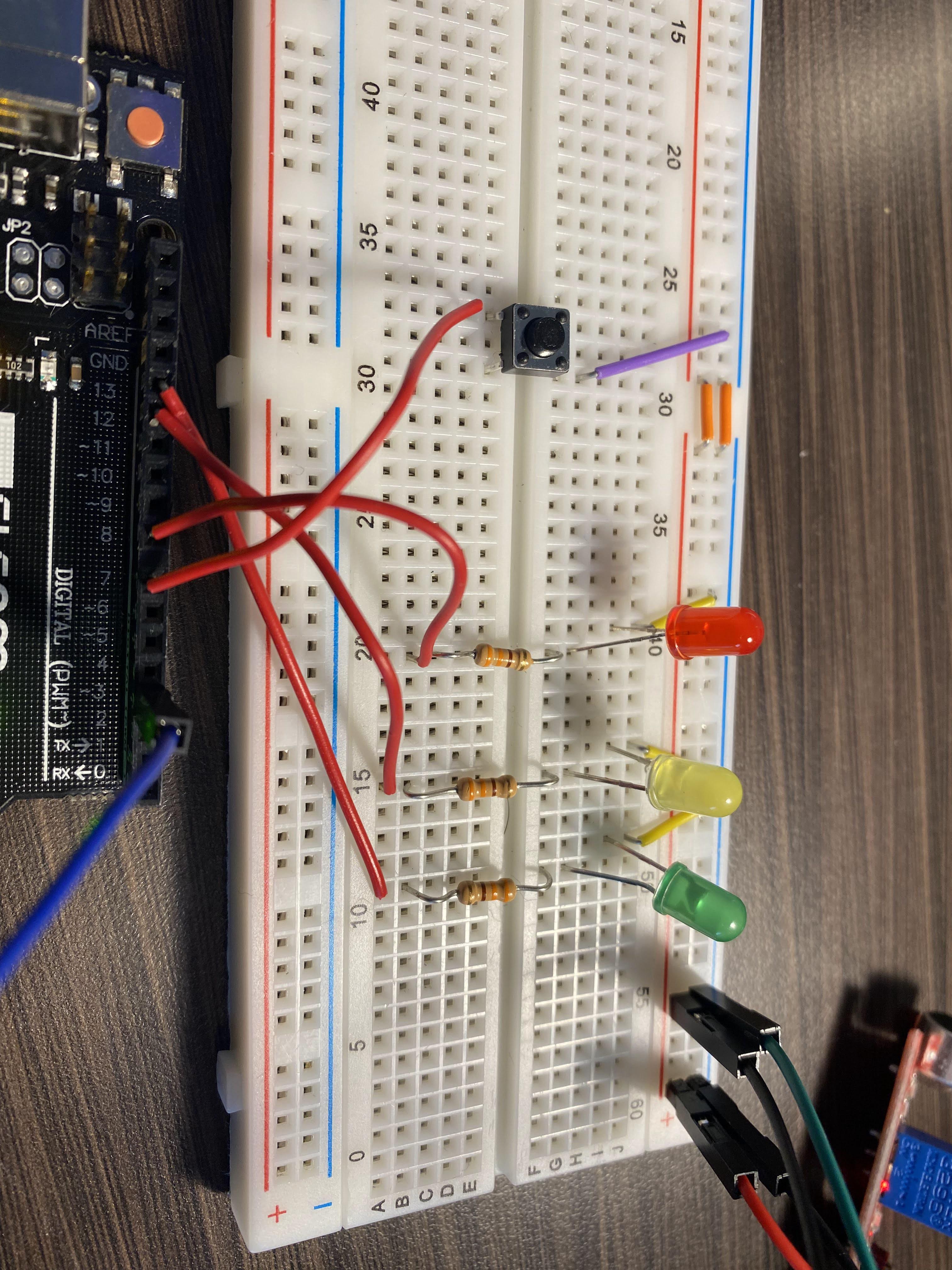
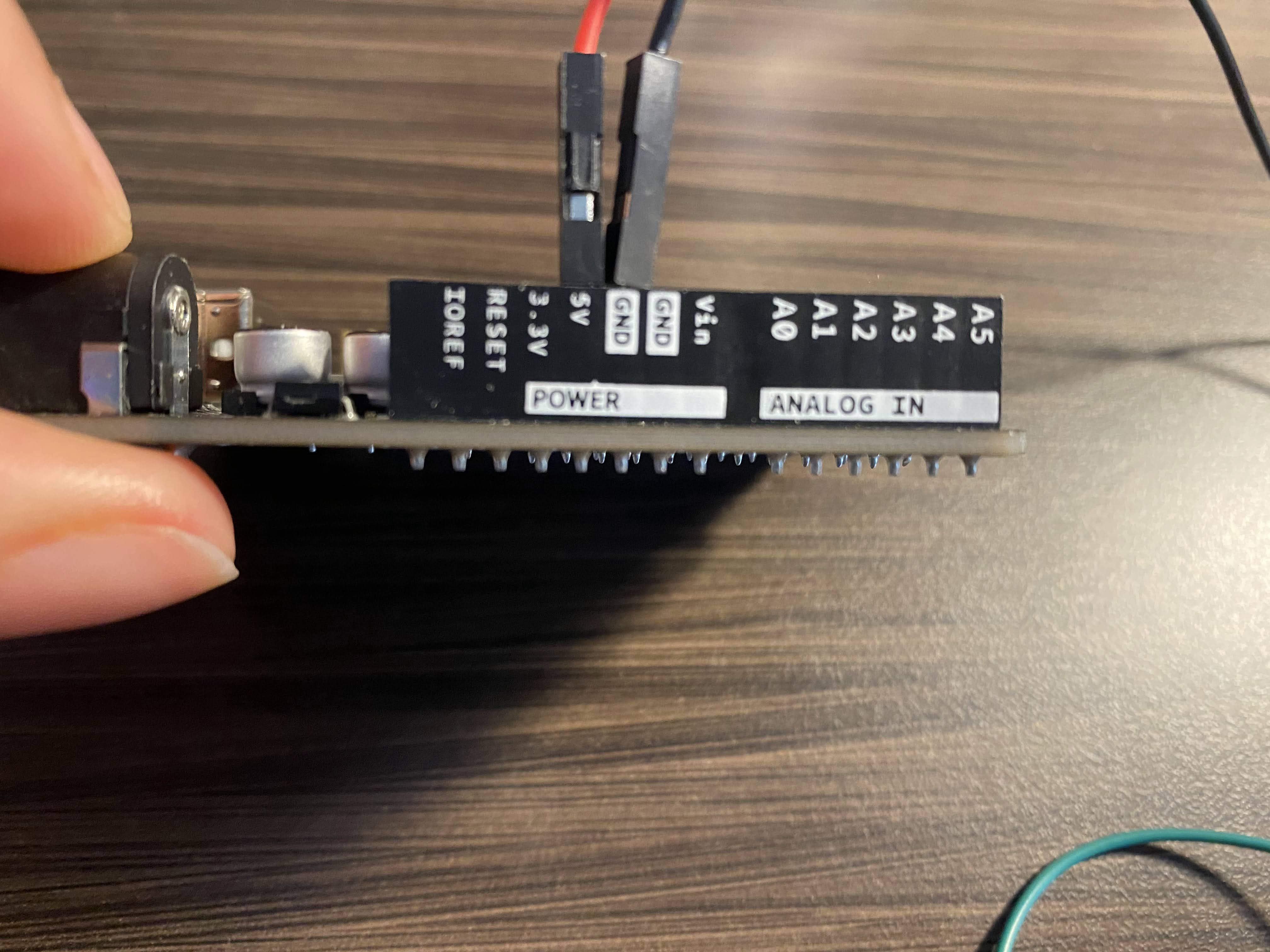
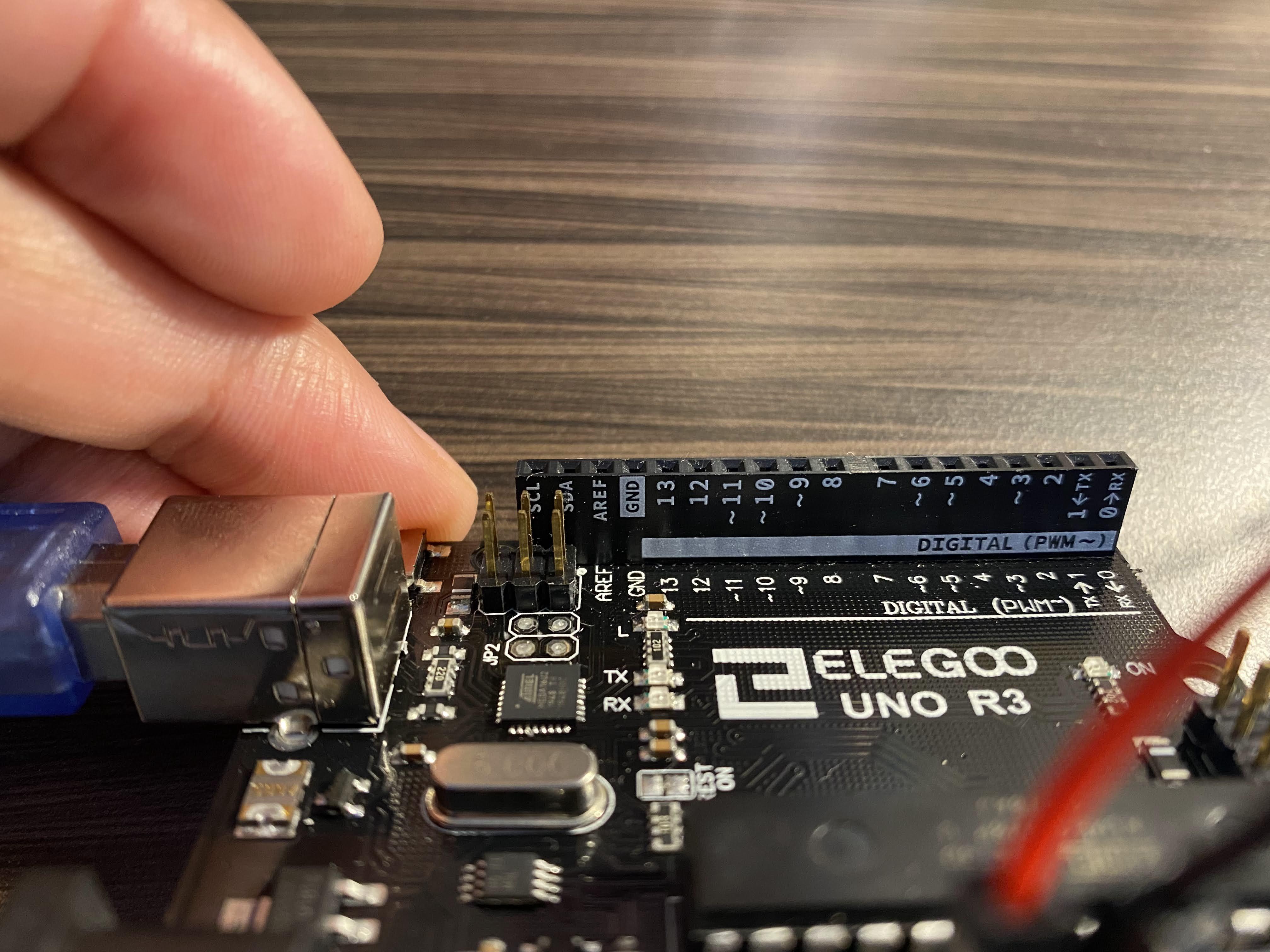
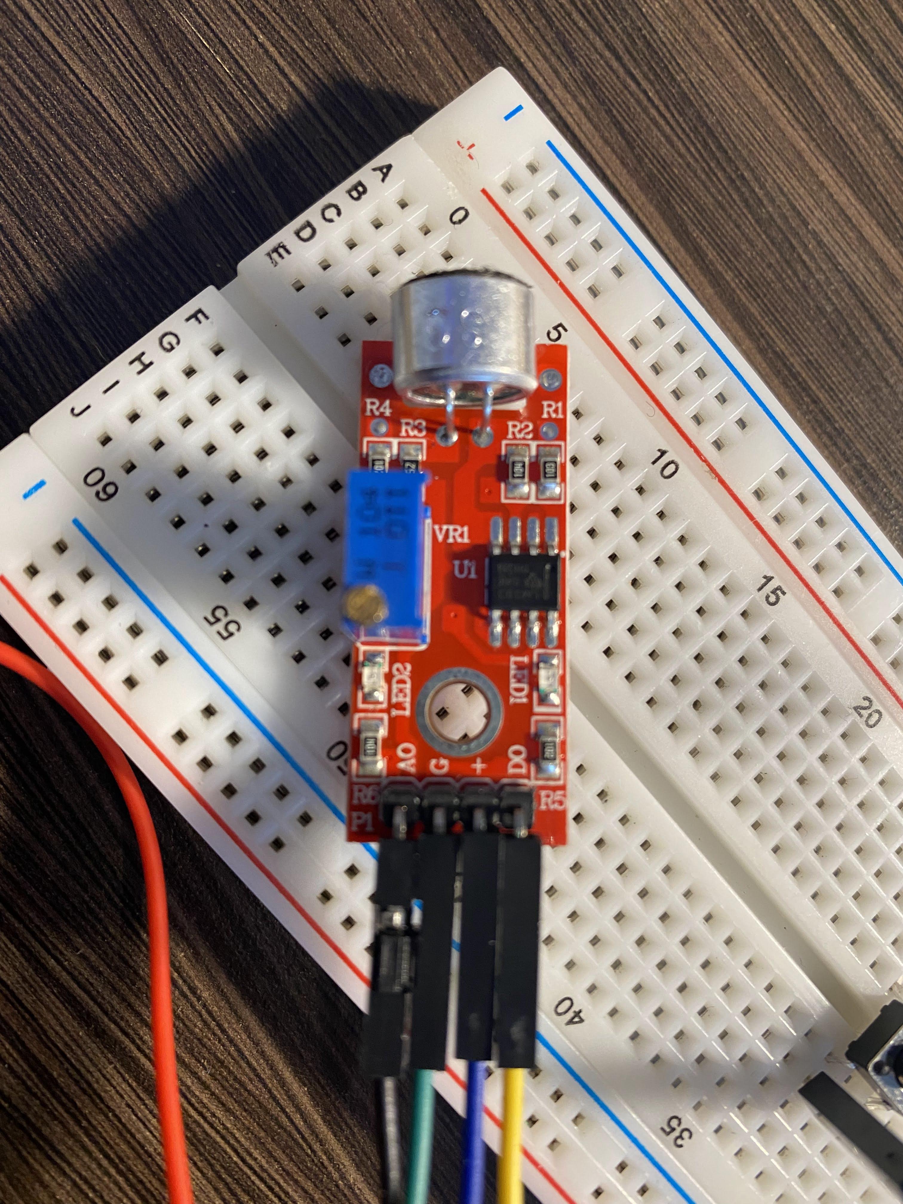
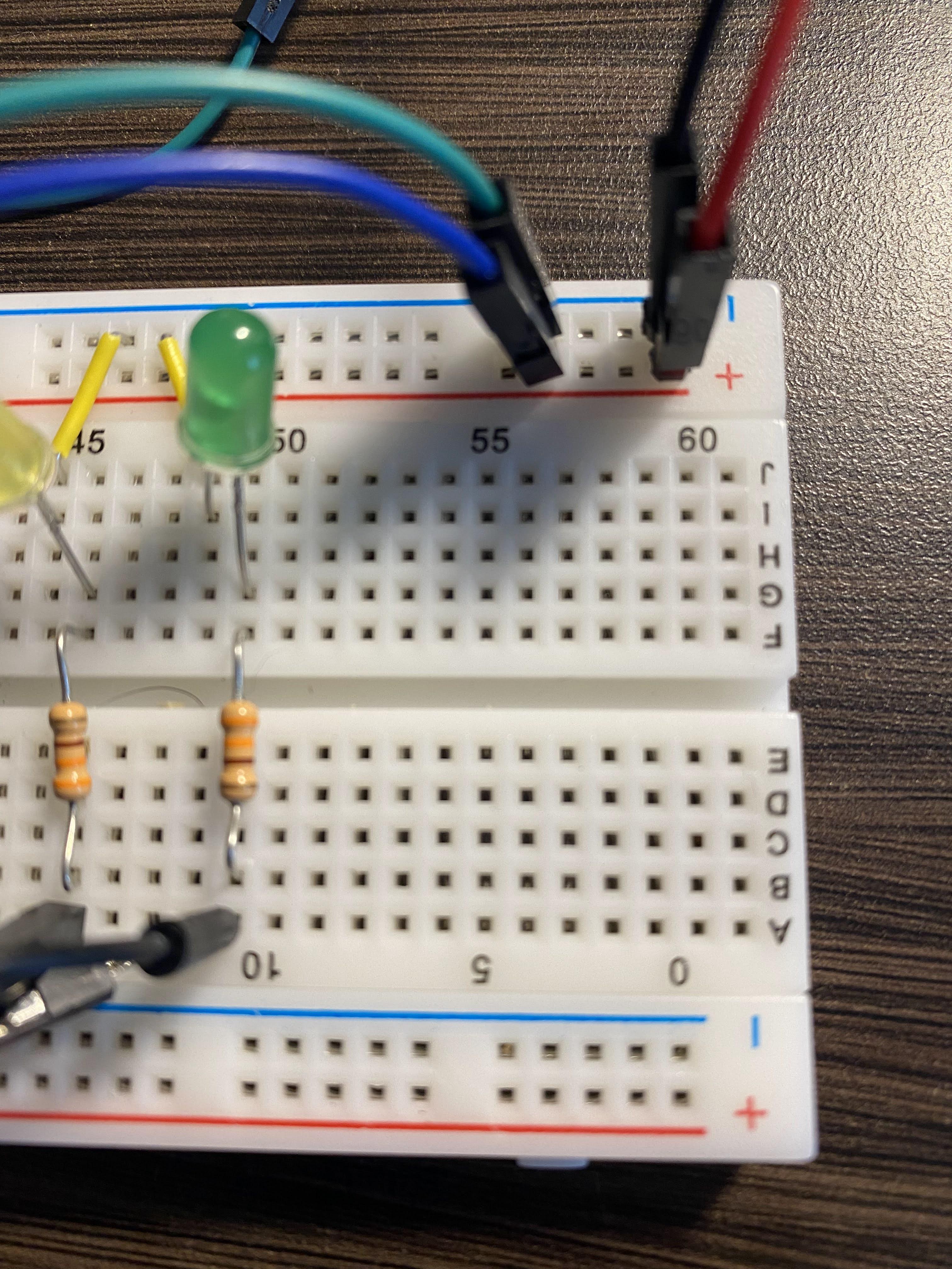
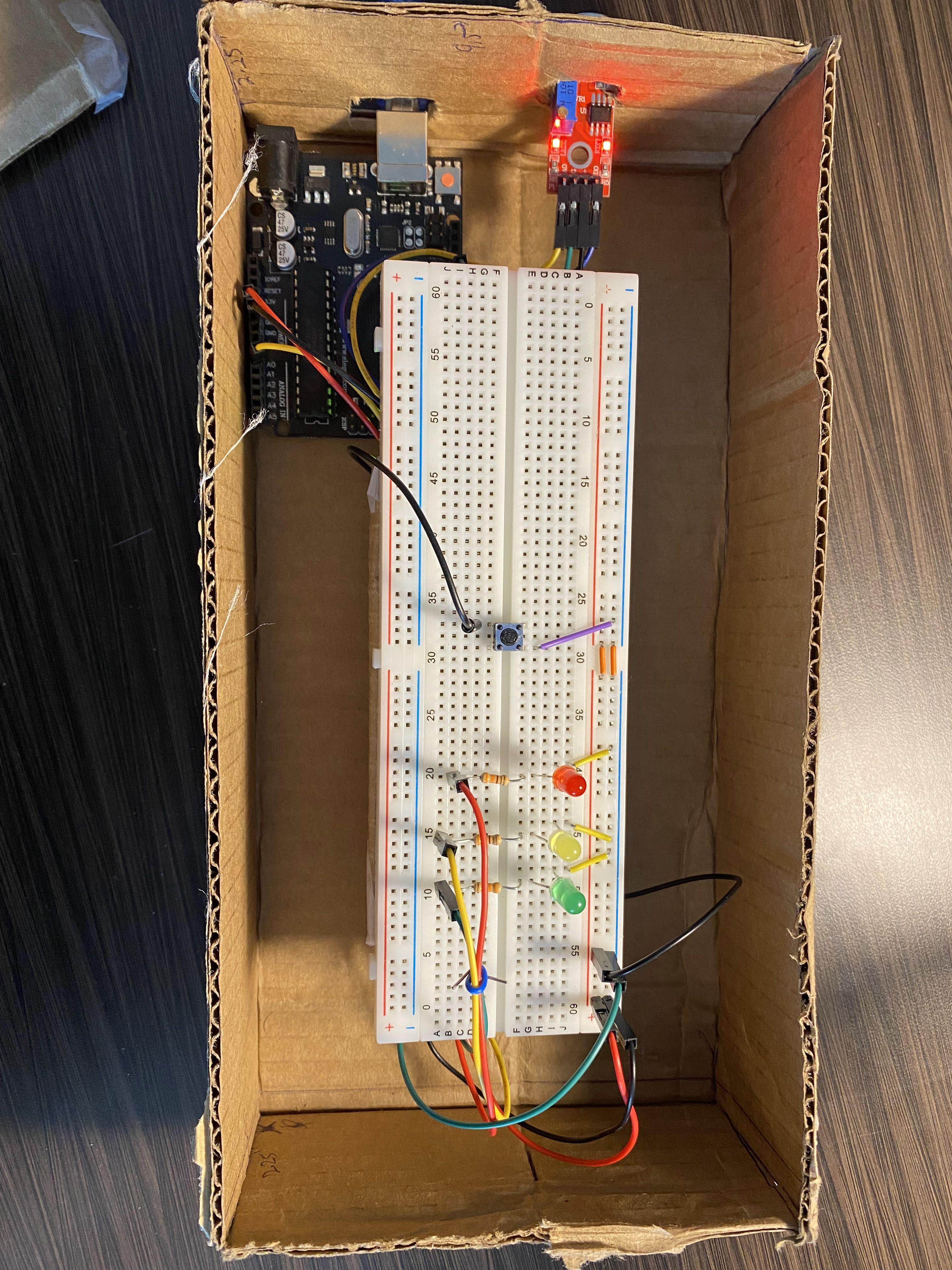
First, you need to wire the electronic components together according to the wiring diagram provided. (The D0 pin of the sensor is not shown in the schematic to the left; It will not be used in the default analog setup.. Therefore no connections are needed to be made to it. However, wiring up the digital pin as stated below will not hurt; there is an alternative control that can be used with it being hooked up.)
Wiring LEDs
- All LEDs are Polarized meaning that power MUST go through the device in a certain direction for it to work properly.
- The negative (shorter side) must be connected to the Ground Bar.
- The positive (longer side) must be connected one end of a 330Ω resistor.
- The other end of the resistor should be connected (or jumpered) to the Power Bar.
Reference [1]
Wiring the Pushbutton
Pushbuttons are not polarized meaning that you can connect power in any direction but… the sides are connected like shown. (When you press down… you close the circuit sending a signal)
- Connect one leg on ‘connected side’ to the Ground Bar (-)
- Connect one leg on the opposing side (i.e. not connected) to Pin 7 on the Arduino.
Reference [2]
Arduino Connections (signal connections):
- SensorAnalogPin: A0 to A0 Pin on Arduino
- SensorDigitalPin: DO to Pin3 (a PWM pin) on Arduino
- PushButton to Pin7 on Arduino
- Red LED to Pin13 on Arduino
- Yellow LED to Pin12 on Arduino
- Green LED to Pin8 on Arduino
- Power to Ardunio:
- USB Cable from computer to Arduino Jack
- Power to BreadBoard:
- Arduino 5V pin to Breadboard Power Bus (+)
- Arduino GND Pin to Breadboard Ground Bus (-)
- Power to Sensor:
- Sensor + Pin to Breadboard Power Bus (+)
- Sensor G Pin to Breadboard Ground Bus (-)
(Schematic & Pictures Attached)
Coding
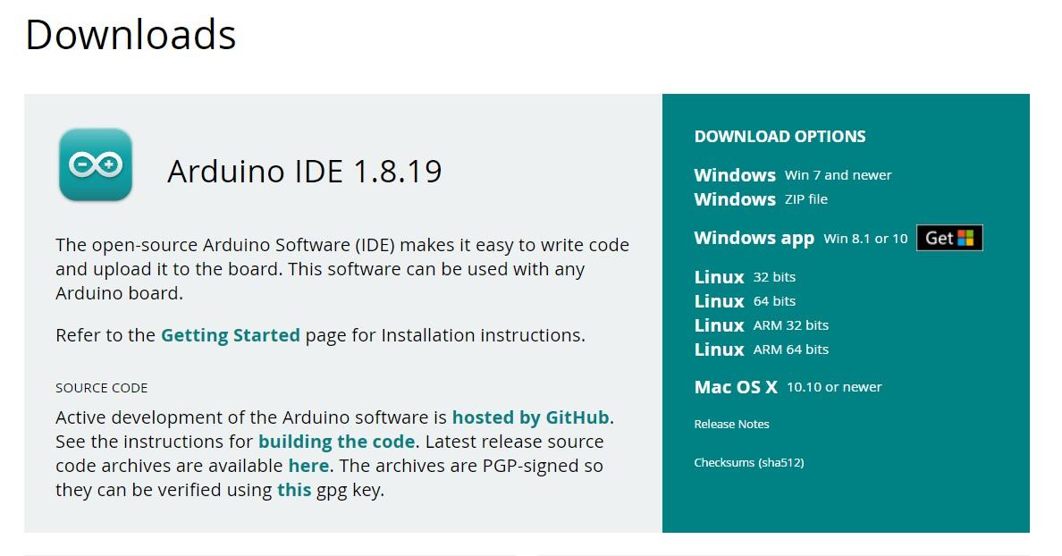


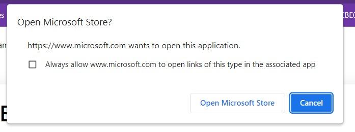
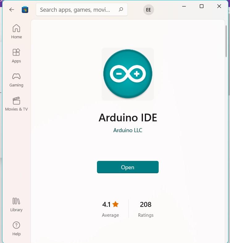
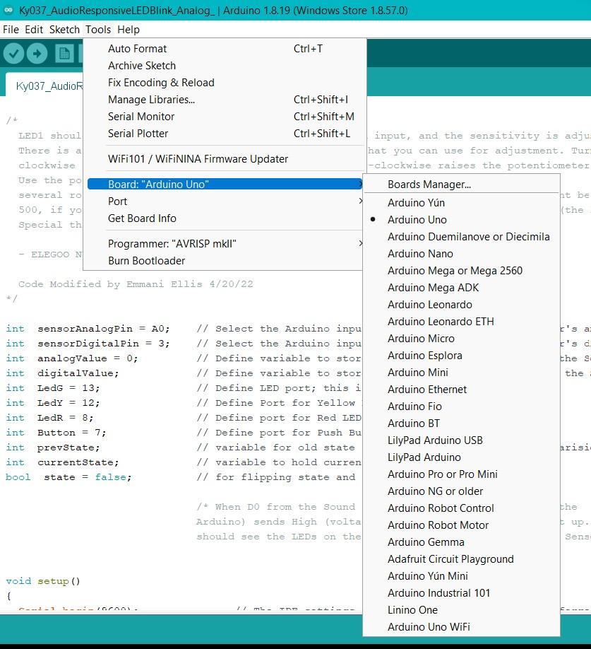
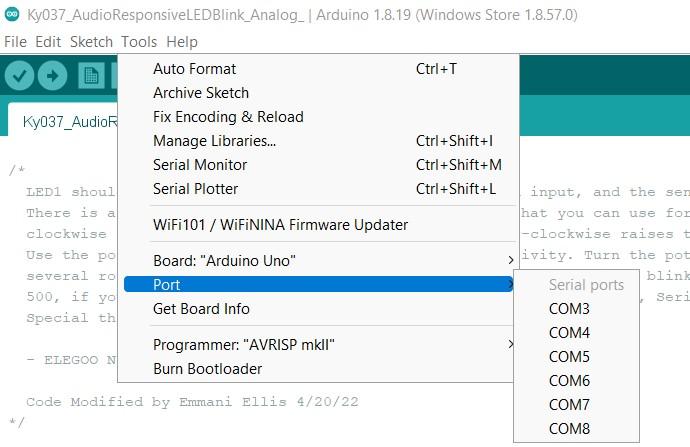
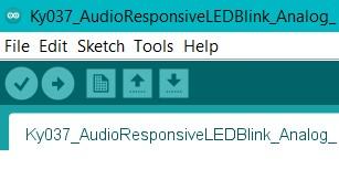
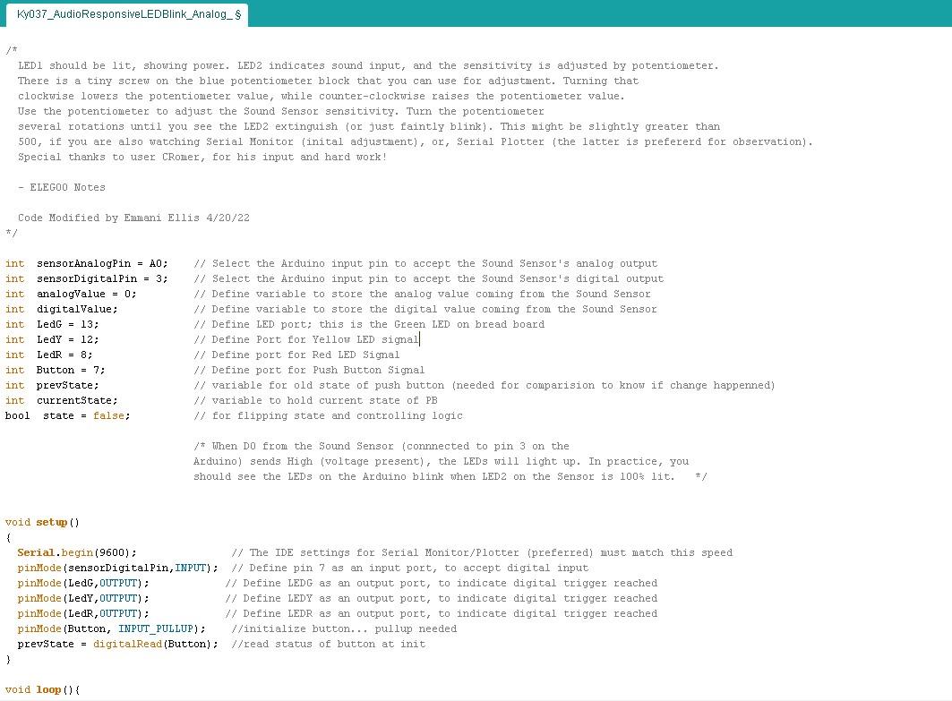
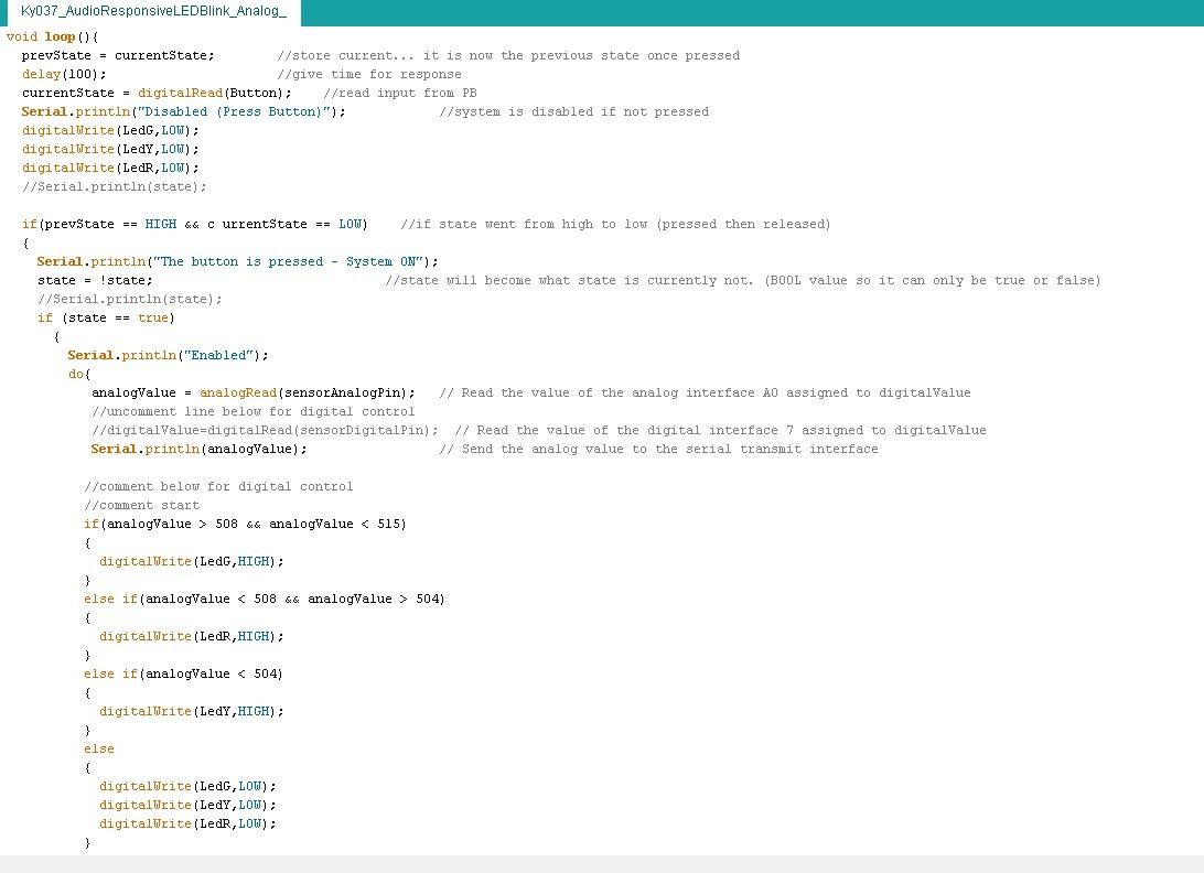
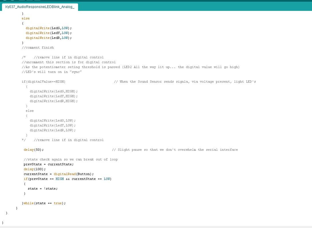
- Software Setup & Configuring (Photo Added are in order)
- Go to Ardunio Site: https://www.arduino.cc/en/software
- The Download page should appear; this page should be shown.
- In the green area, select the download option best compatible with your system. (This guide will follow the Windows app download option)
- The screen below should appear > press “Just Download”
- You should see this screen below. Click “Get”.
- Click “Open Microsoft Store”.
- Click “Get” again. The app should start downloading. Once it is done downloading, you will see “Open”.
- Press “Open”. To Configure: Go to Tools > Board > Arduino Uno.
- Setting the Port: Tools > Port > Select the COM# that the USB is currently in, in your computer. (If you don’t know, try different ones. It will give an error if it is the wrong port)
- Verify by pressing the Check Mark; Upload by pressing the Right-Facing Arrow. (Verifying is Error Detection while Uploading is sending the Code out to run)
- Audio Responsive System Code Download - https://drive.google.com/file/d/1RUuuHgNx04pnFyE6ujCDh8tM05j-8dWH/view?usp=sharing
- Screenshot Code Snippets Attached: Code Block Below (Comment are added to explain the individual lines)
/*
  LED1 should be lit, showing power. LED2 indicates sound input, and the sensitivity is adjusted by potentiometer. There is a tiny screw on the blue potentiometer block that you can use for adjustment. Turning that clockwise lowers the potentiometer value, while counter-clockwise raises the potentiometer value. Use the potentiometer to adjust the Sound Sensor sensitivity. Turn the potentiometer several rotations until you see the LED2 extinguish (or just faintly blink). This might be slightly greater than 500, if you are also watching Serial Monitor (inital adjustment), or, Serial Plotter (the latter is prefererd for observation). Special thanks to user CRomer, for his input and hard work!

  - ELEGOO Notes

  Code Modified by Emmani Ellis 4/20/22
*/


int  sensorAnalogPin = A0;    // Select the Arduino input pin to accept the Sound Sensor's analog output
int  sensorDigitalPin = 3;    // Select the Arduino input pin to accept the Sound Sensor's digital output
int  analogValue = 0;         // Define variable to store the analog value coming from the Sound Sensor
int  digitalValue;            // Define variable to store the digital value coming from the Sound Sensor
int  LedG = 13;               // Define LED port; this is the Green LED on bread board
int  LedY = 12;               // Define Port for Yellow LED signal
int  LedR = 8;                // Define port for Red LED Signal
int  Button = 7;              // Define port for Push Button Signal
int  prevState;               // variable for old state of push button (needed for comparision to know if change happenned)
int  currentState;            // variable to hold current state of PB
bool  state = false;          // for flipping state and controlling logic


                           /* When D0 from the Sound Sensor (connnected to pin 3 on the
Arduino) sends High (voltage present), the LEDs will light up. In practice, you should see the LEDs on the Arduino blink when LED2 on the Sensor is 100% lit.   */


void setup()
{
  Serial.begin(9600);               // The IDE settings for Serial Monitor/Plotter (preferred) must match this speed
  pinMode(sensorDigitalPin,INPUT);  // Define pin 7 as an input port, to accept digital input
  pinMode(LedG,OUTPUT);            // Define LEDG as an output port, to indicate digital trigger reached
  pinMode(LedY,OUTPUT);            // Define LEDY as an output port, to indicate digital trigger reached
  pinMode(LedR,OUTPUT);            // Define LEDR as an output port, to indicate digital trigger reached
  pinMode(Button, INPUT_PULLUP);    //initialize button... pullup needed
  prevState = digitalRead(Button);  //read status of button at init
}


void loop(){
  prevState = currentState;        //store current... it is now the previous state once pressed
  delay(100);                      //give time for response
  currentState = digitalRead(Button);    //read input from PB
  Serial.println("Disabled (Press Button)");            //system is disabled if not pressed
  digitalWrite(LedG,LOW);
  digitalWrite(LedY,LOW);
  digitalWrite(LedR,LOW);
  //Serial.println(state);

  if(prevState == HIGH && currentState == LOW)    //if state went from high to low (pressed then released)
  {
    Serial.println("The button is pressed - System ON");
    state = !state;                              //state will become what state is currently not. (BOOL value so it can only be true or false)
    //Serial.println(state);
    if (state == true)
      {
        Serial.println("Enabled");
        do{
           analogValue = analogRead(sensorAnalogPin);   // Read the value of the analog interface A0 assigned to digitalValue
           //uncomment line below for digital control
           //digitalValue=digitalRead(sensorDigitalPin);  // Read the value of the digital interface 7 assigned to digitalValue
           Serial.println(analogValue);                 // Send the analog value to the serial transmit interface

          //comment below for digital control
          //comment start
          if(analogValue > 508 && analogValue < 515)
          {
            digitalWrite(LedG,HIGH);
          }
          else if(analogValue < 508 && analogValue > 504)
          {
            digitalWrite(LedR,HIGH);
          }
          else if(analogValue < 504)
          {
            digitalWrite(LedY,HIGH);
          }
          else
          {
            digitalWrite(LedG,LOW);
            digitalWrite(LedY,LOW);
            digitalWrite(LedR,LOW);
          }
          //comment finish

          /*    //remove line if in digital control
          //uncomment this section is for digital control
          //As the potentiometer seting threshold is passed (LED2 All the way lit up... the digital value will go high)
          //LED's will turn on in "sync"

          if(digitalValue==HIGH)                        // When the Sound Sensor sends signla, via voltage present, light LED's
            {
              digitalWrite(LedG,HIGH);
              digitalWrite(LedY,HIGH);
              digitalWrite(LedR,HIGH);
            }
            else
            {
              digitalWrite(LedG,LOW);
              digitalWrite(LedY,LOW);
              digitalWrite(LedR,LOW);
            }
          */    //remove line if in digital control

           delay(50);                                  // Slight pause so that we don't overwhelm the serial interface

           //state check again so we can break out of loop
           prevState = currentState;
           delay(100);
           currentState = digitalRead(Button);
           if(prevState == HIGH && currentState == LOW)
           {
             state = !state;
           }

          }while(state == true);
       }
  }

}
Testing the System
Video to how it should work - https://photos.app.goo.gl/iCcd2WMpijKu8Dgi6
Tuning - https://photos.app.goo.gl/s8cnVKA9Hwt1NHcBA
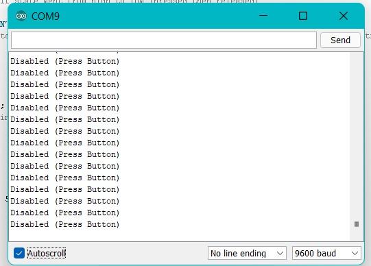
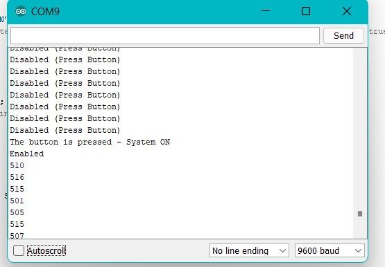
- If viewing the serial monitor, you should see the above similar in your serial monitor. (Disabled when off; Enabled when on)
Create Housing
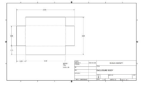
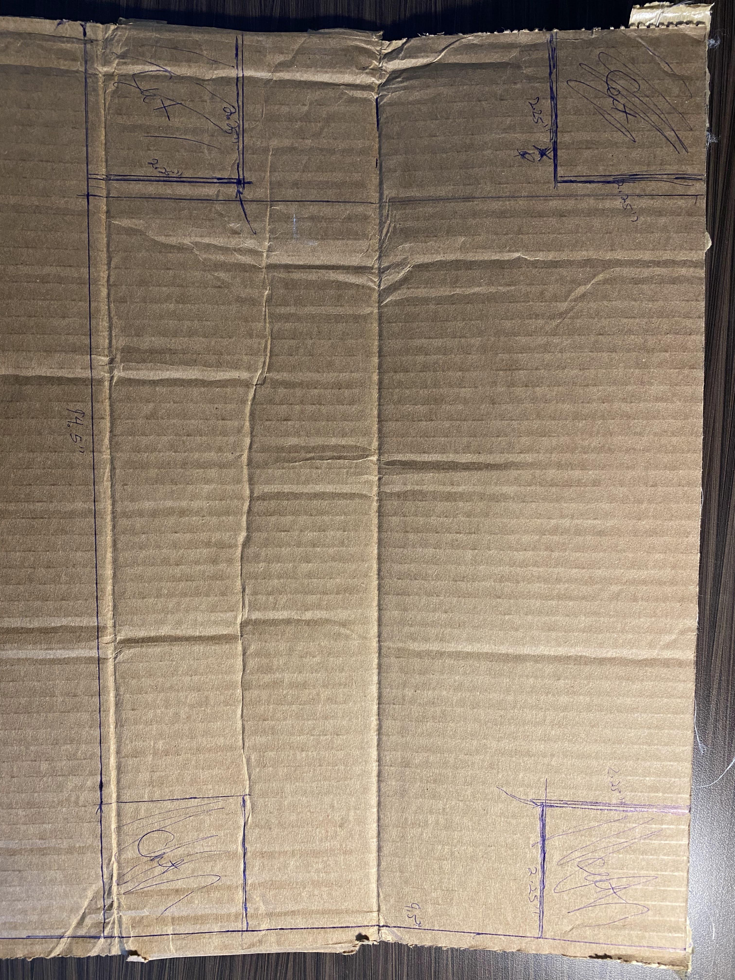
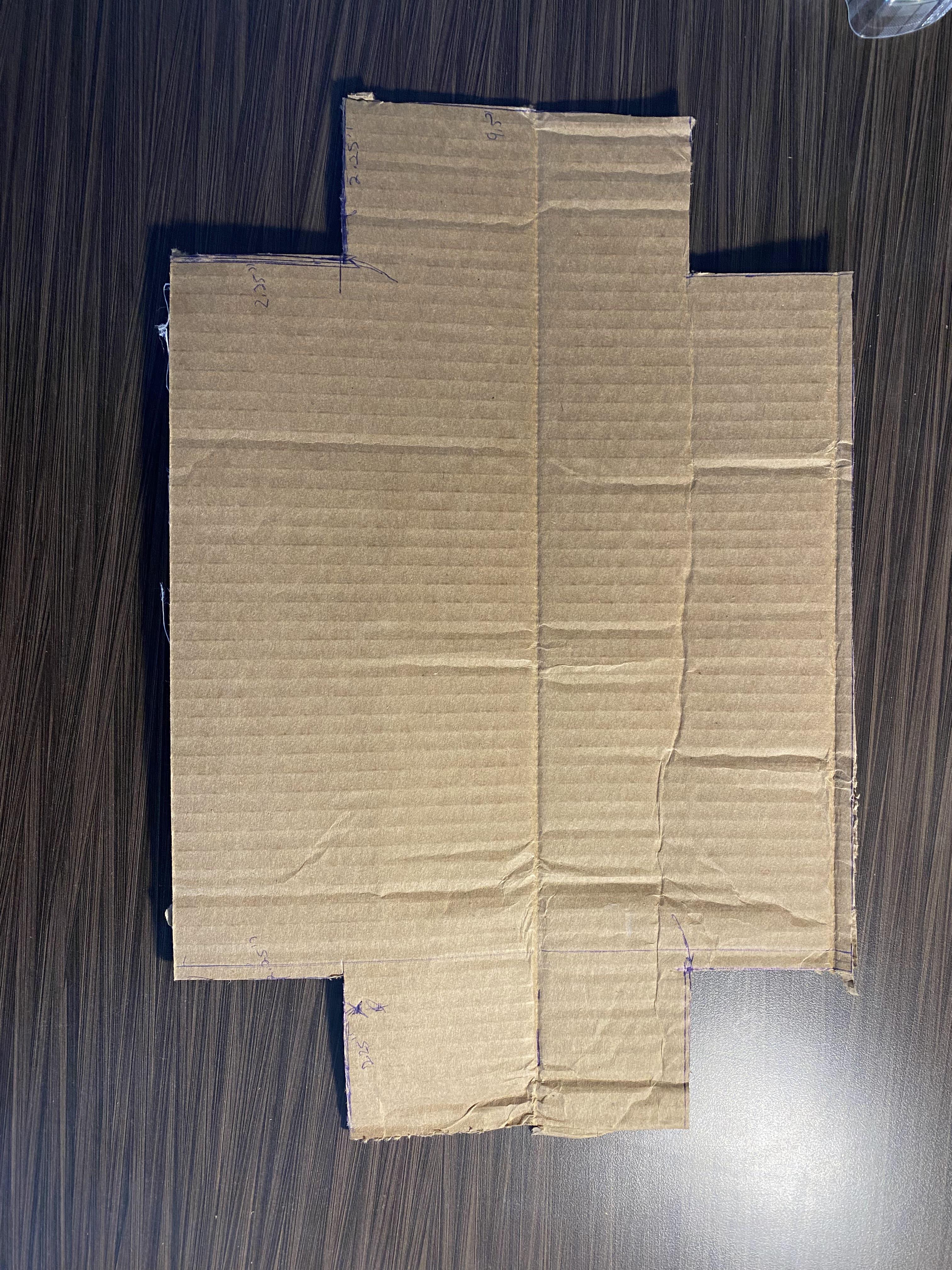
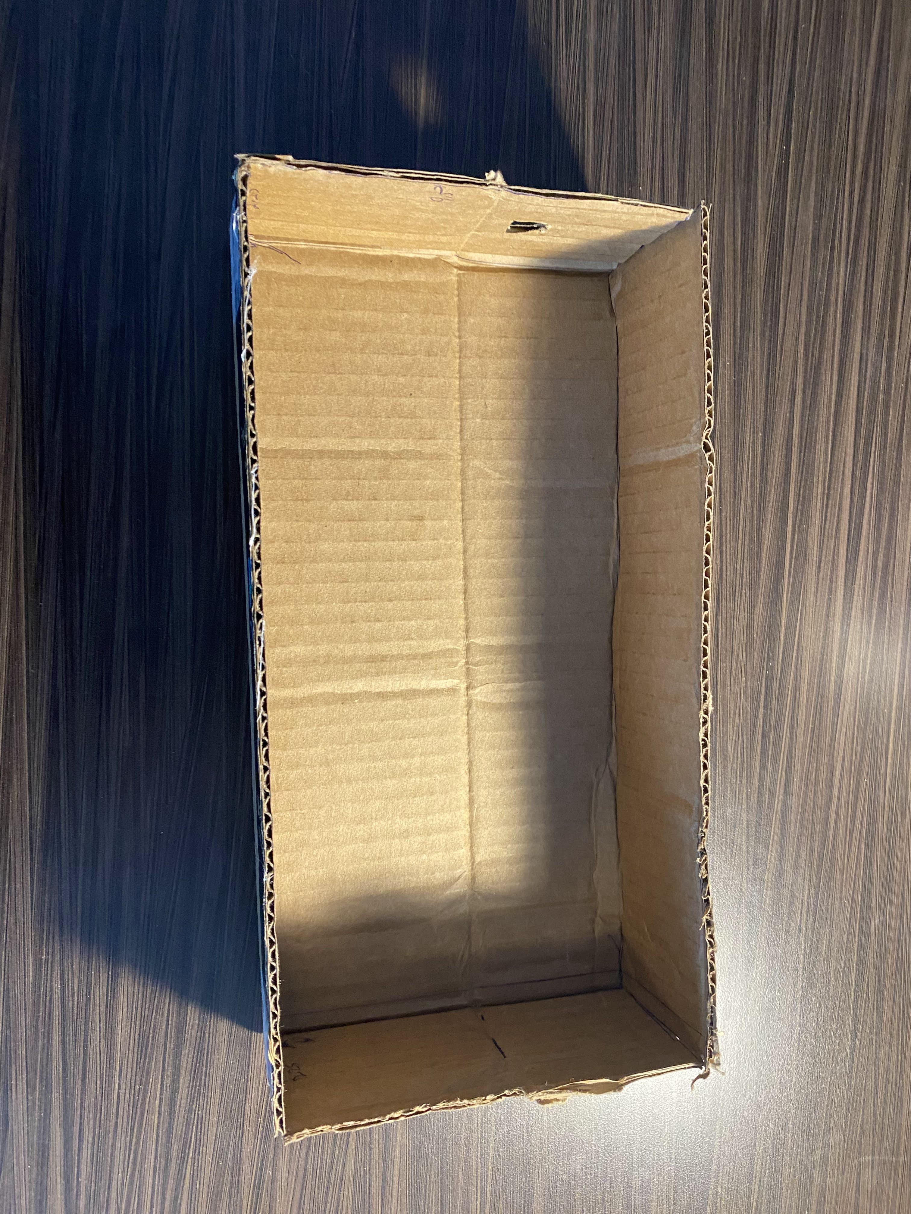
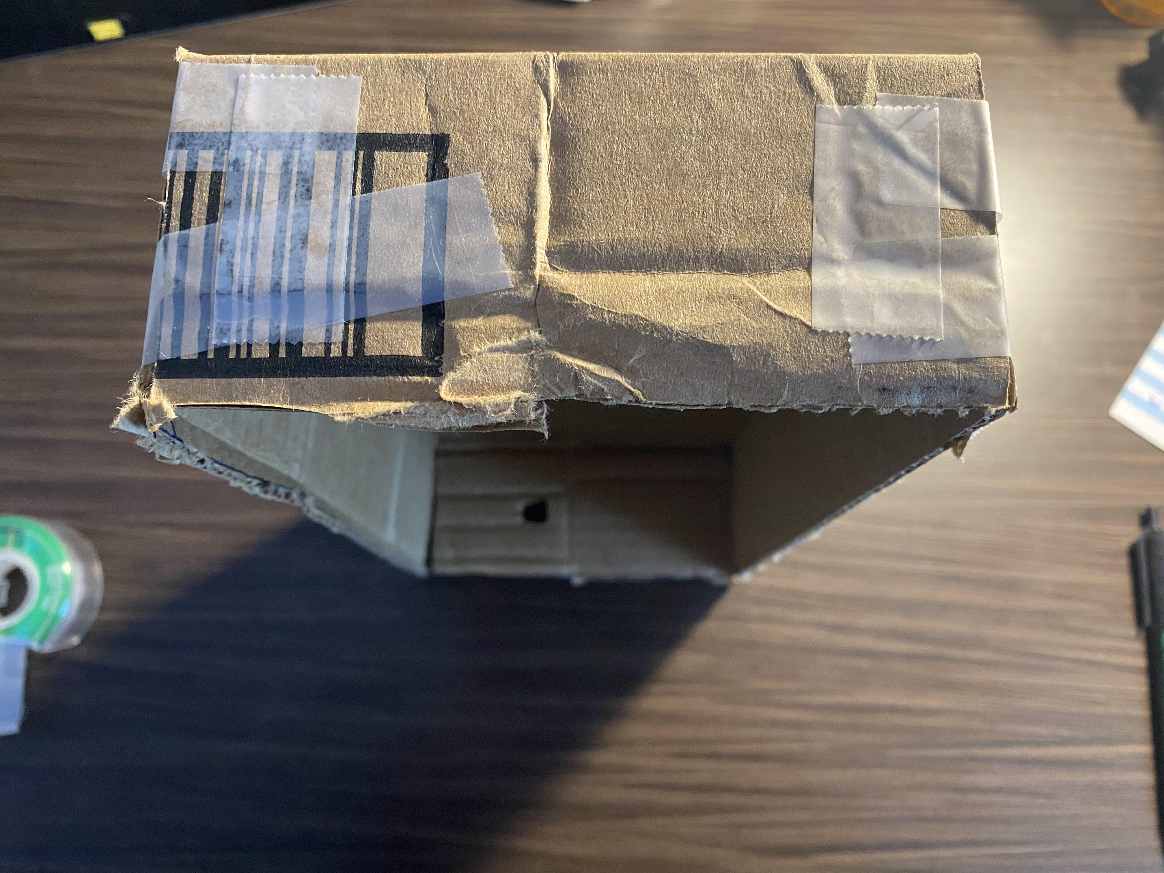
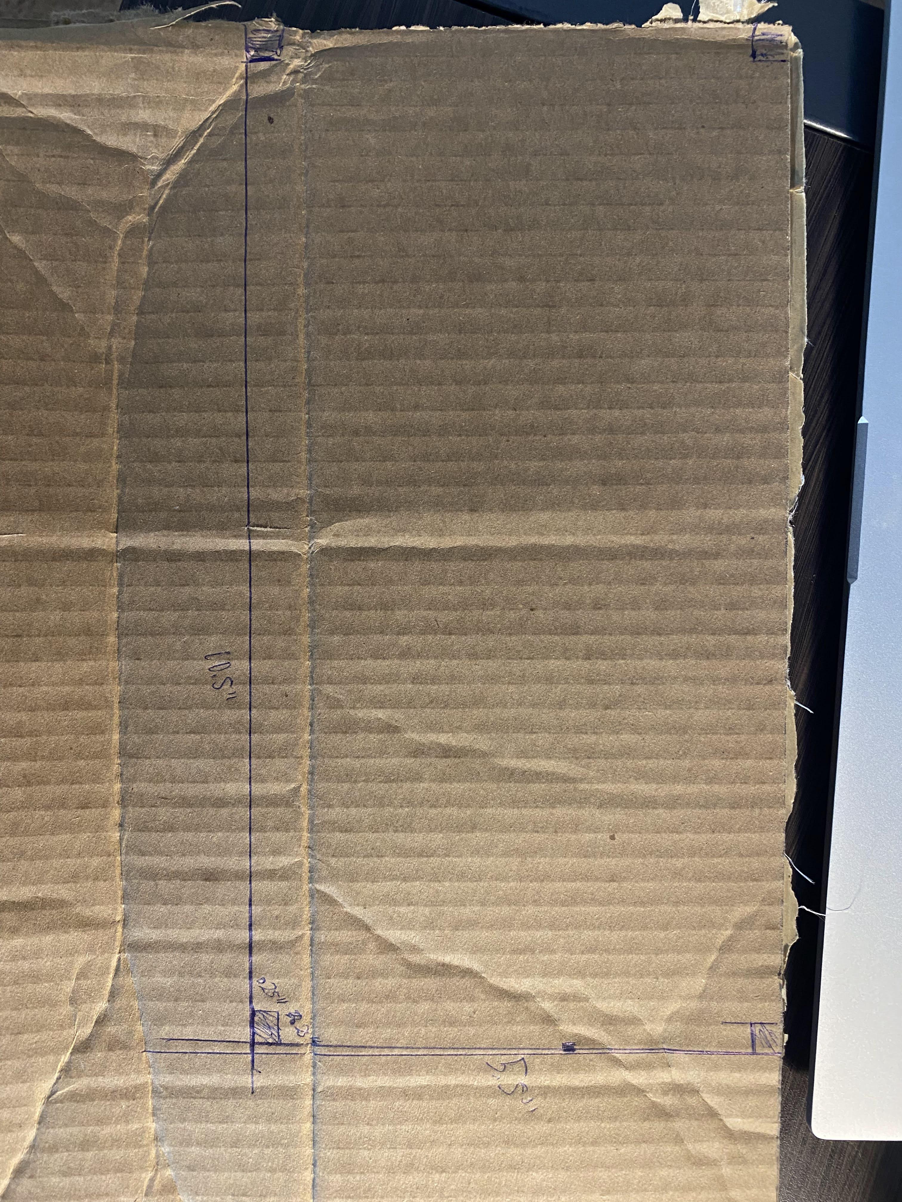
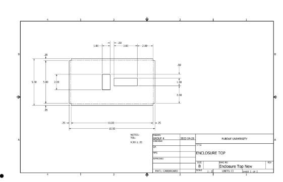
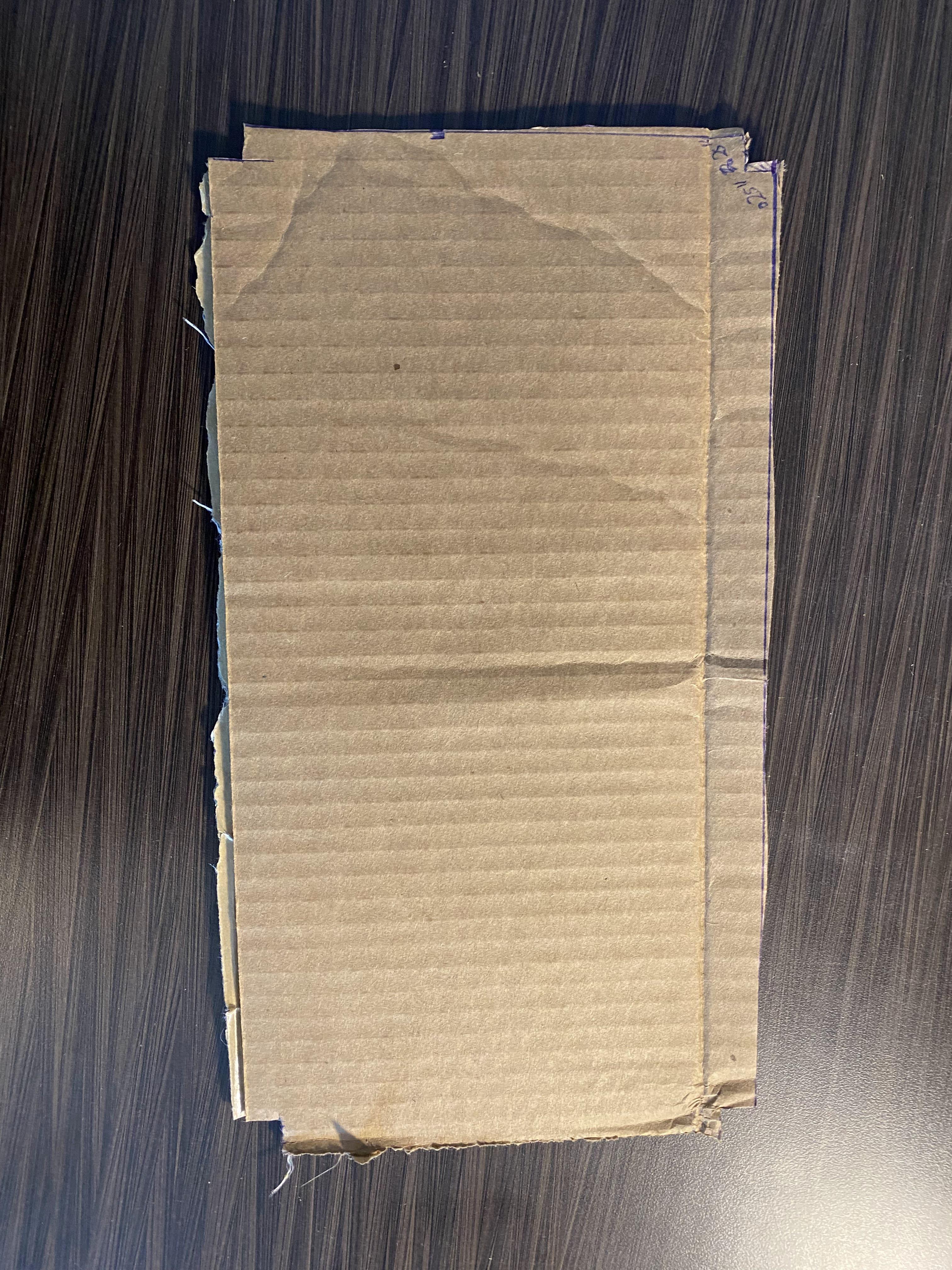
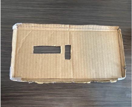
- Make Bottom Holder Video: https://photos.app.goo.gl/Zx5uP5xEJwKQtz2w7
- Place Flat Cardboard on a surface that you do not mind scratching up or place something under it
- Measure out folds for the sides of the container
- Add Cut Measurements according to Drawing
- Tips for Drawing Straight Line
- Mark the desired measurement them use a ruler to create a straight light to cut on
- Cut a minimum 0.5” x 0.5” size hole for speaker on side
- Use Box Cutter to cut out the container
- Fold Sides Up Video: https://photos.app.goo.gl/GQcQgSUiyPueFSqW6
- Tape Sides
- Make Top Cover
- Place Flat Cardboard on a surface that you do not mind scratching up or place something under it
- Measure out folds for the sides of the cover
- Add Cut Measurements according to Drawing
- Tips for Drawing Straight Line
- Mark the desired measurement them use a ruler to create a straight light to cut on
- Cut Viewing Panel for LED & Push buttons (varies based on your circuit wiring)
- Use Box Cutter to cut cover
- Fold Sides Up
- Tape Sides
Putting It All Together
Putting it All Together:
- PT 1 Breadboard Stand:(Optional) https://photos.app.goo.gl/AWmhZNc98QZVjZwd8
- PT 2 Inserting Stand: (Optional) https://photos.app.goo.gl/xvr1zY8StEJt3SK96
- PT 3 Stability + Putting on Lid: https://photos.app.goo.gl/B8iUi2KbqkSsX2kWA
- PT 4 Finished Product: https://photos.app.goo.gl/QiMXehiRynCseZfG9
References
References:
[1] “Owlcircuits,” OwlCircuits.com | LED Polarity Identification, 29-Mar-2019. [Online]. Available: https://owlcircuits.com/resources/how-to-determine-led-polarity/. [Accessed: 27-Apr-2022].
[2] “Arduino: Pushbutton,” shallowsky.com. [Online]. Available: https://shallowsky.com/arduino/class/button.html. [Accessed: 27-Apr-2022].