DIY Addressable RGB LED Strip Controller
by Northstrix in Circuits > Microcontrollers
2079 Views, 13 Favorites, 0 Comments
DIY Addressable RGB LED Strip Controller
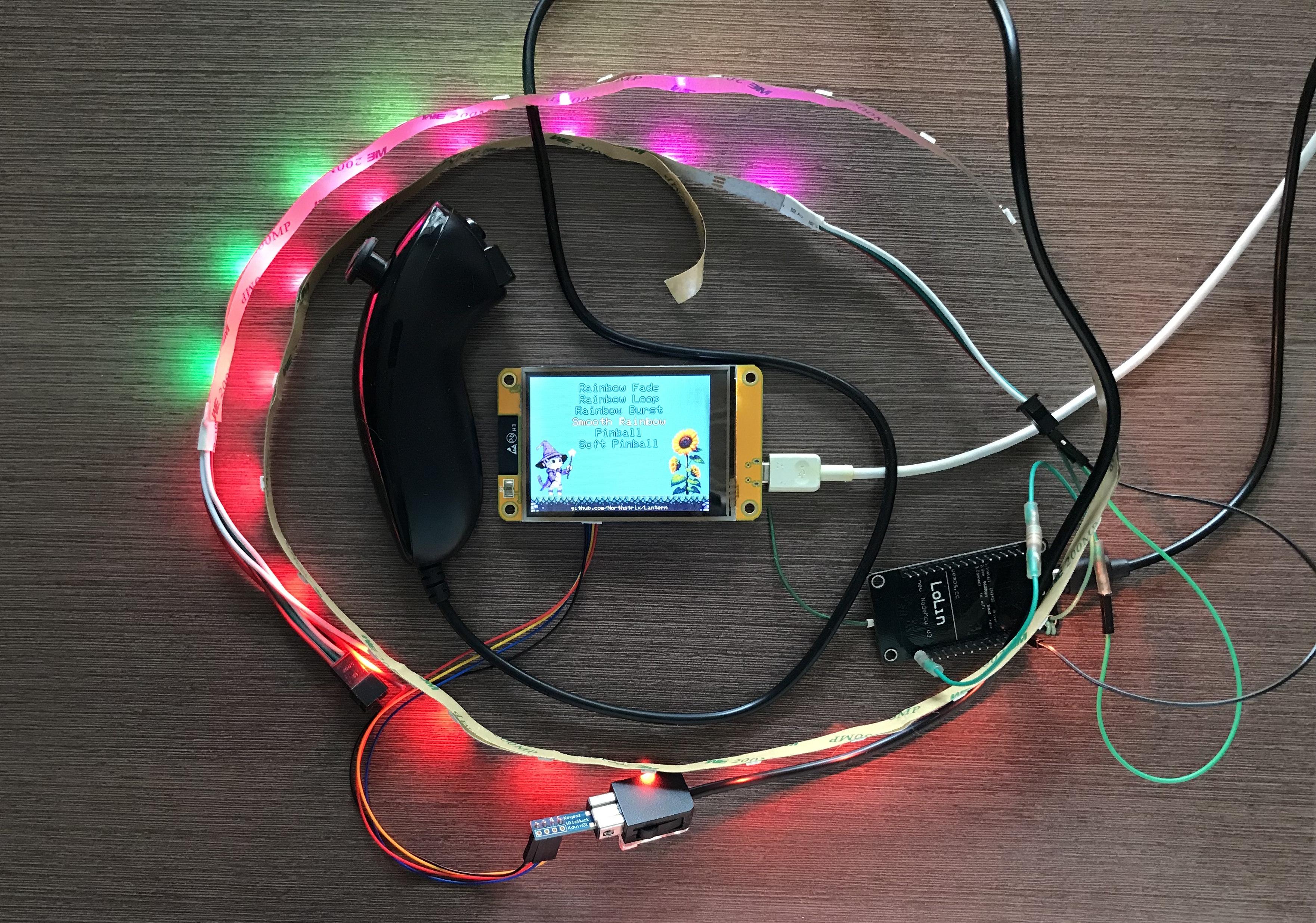
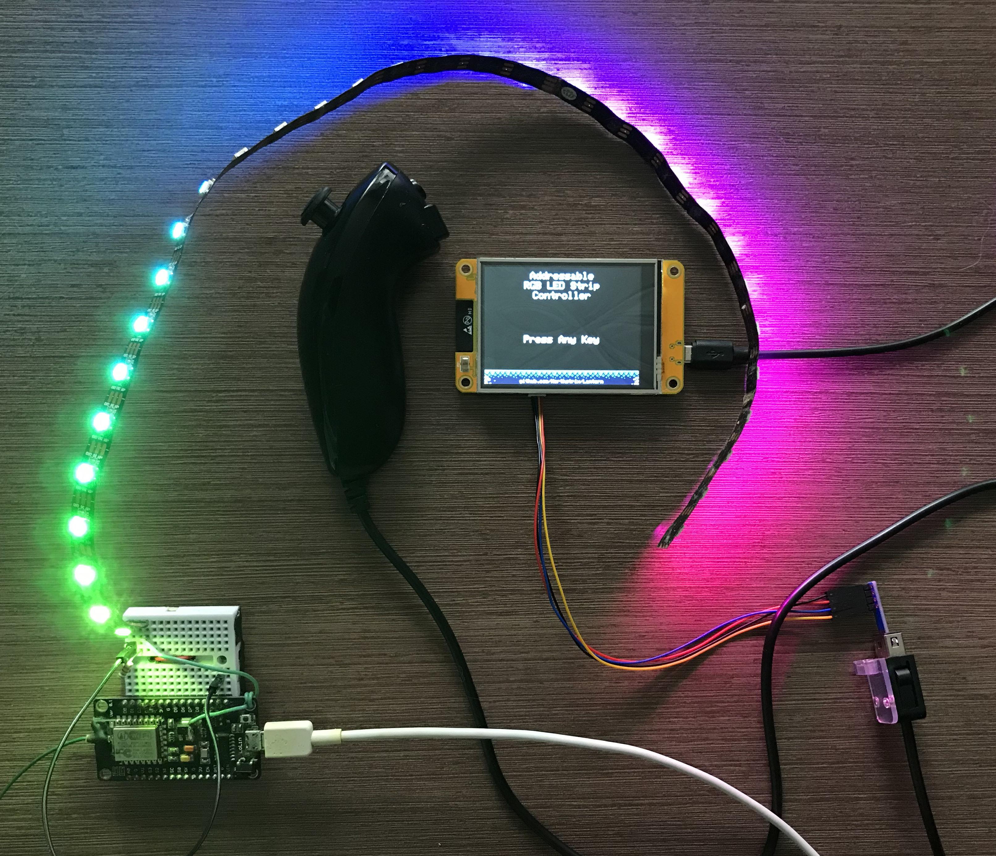
The Lantern project is an ESP-based addressable RGB LED strip controller.
It employs two ESPs: an ESP32 connected to a Nintendo Wii Nunchuk, which functions as a remote, and an ESP8266 connected to a WS2812 LED strip, which acts as the receiver and drives the strip.
The Lantern project offers 32 different modes and employs basic cryptographic features (that at least prevent separate transmitter-receiver pairs from interfering with one another).
Before you continue reading this tutorial, please note that I did not create any of the effects demonstrated here. All effects are sourced from here and are the property of their respective owners.
If you just want to make this device, go straight to step 8.
Supplies
Supplies for the transmitter:
- ESP32-2432S028R x1;
- Nintendo Wii Nunchuk x1;
- WiiChuck Nunchuck Adapter (PCB Board) x1.
Supplies for the receiver:
- ESP8266 x1;
- 580 Ohm resistor x1;
- WS2812 LEDs x(as much as you need).
How It Came to Be
Recently, I've been following the Java Game Development Tutorial from Kaarin Gaming. Although I haven't completed the game (but nevertheless borrowed a soil sprite from it), I've already created sprites for it.
So, I just figured I shouldn't let all these sprites go to waste, and after several hours of consideration, I've decided to incorporate some of these sprites into the Addressable RGB LED Strip Controller.
By the way, I've placed all the sprites I created, along with the original images generated by Microsoft's Image Creator, into the ".../V1.1/extra/Images" folder.
Image Generation
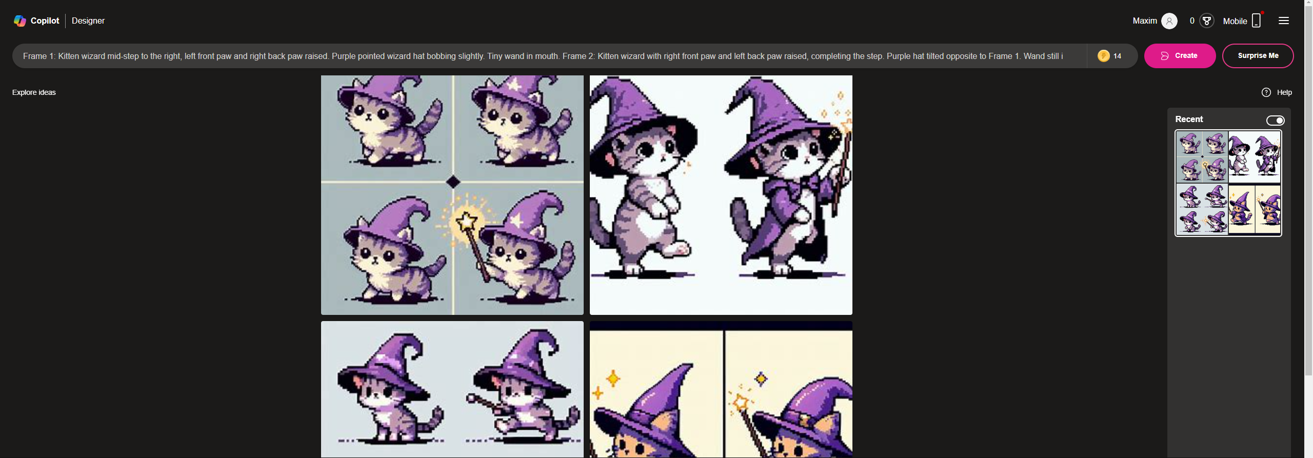
I've asked Microsoft's Image Creator to generate some images using the prompts I got from the Perplexity. And I would say I'm satisfied with the result.
You can find the prompts in the folders with the images.
Note that the Image Creator should give you different results, even if you use the exact same prompts multiple times.
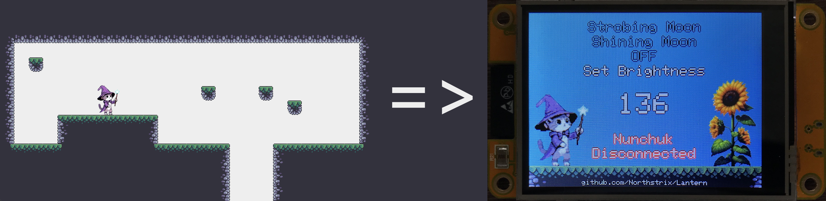
Sprite Creation
After resizing the images and removing the background, I began manually editing the sprites. Eventually, I saved the sprites into the .png files with the transparent backgrounds.
Displaying the Sprite
Well, I could've just converted the cat sprite using the image convertor from the DIY Hardware Data Vault With Teensy 4.1 (Midbar (Teensy 4.1) V3.0), but I've decided to take the hard route. I took the code from the Bodmer/PNG_TEST_ONLY repository, analyzed it, tested it, modified it, fed it to Perplexity, then modified and tested it again, and repeated the cycle until I got the desired result.
Sprite Partitioning
To change the sprite even faster, I've only decided to redraw the moving part. To do that, I divided the sprite into two components: a static single-handed cat and interchangeable hands. When the sprite is updated, the current hand is erased using one of the functions demonstrated below, and the new one is drawn in its place.
void erase_default_hand() {
 tft.fillRect(58 + OFFSET_CAT_BY_X, 14 + OFFSET_CAT_BY_Y, 19, 13, COMMON_FILL_COLOR);
 tft.fillRect(61 + OFFSET_CAT_BY_X, 27 + OFFSET_CAT_BY_Y, 10, 37, COMMON_FILL_COLOR);
 tft.fillRect(55 + OFFSET_CAT_BY_X, 41 + OFFSET_CAT_BY_Y, 6, 30, COMMON_FILL_COLOR);
 tft.fillRect(48 + OFFSET_CAT_BY_X, 50 + OFFSET_CAT_BY_Y, 7, 14, COMMON_FILL_COLOR);
}

void erase_attack_hand() {
 tft.fillRect(48 + OFFSET_CAT_BY_X, 50 + OFFSET_CAT_BY_Y, 27, 13, COMMON_FILL_COLOR);
 tft.fillRect(59 + OFFSET_CAT_BY_X, 63 + OFFSET_CAT_BY_Y, 7, 8, COMMON_FILL_COLOR);
 tft.fillRect(61 + OFFSET_CAT_BY_X, 18 + OFFSET_CAT_BY_Y, 25, 32, COMMON_FILL_COLOR);
}
Input Handling
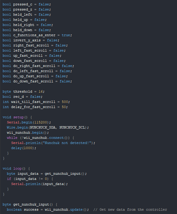
I decided to use the Nintendo Wii Nunchuk to control the remote. To do so, I took the part of the code responsible for handling the Nunchuk from the Midbar (STM32F407VET6 Version) V2.0, fed it to Perplexity a couple of times, modified it a bit and got it working the way I wanted to.
Menu Optimization
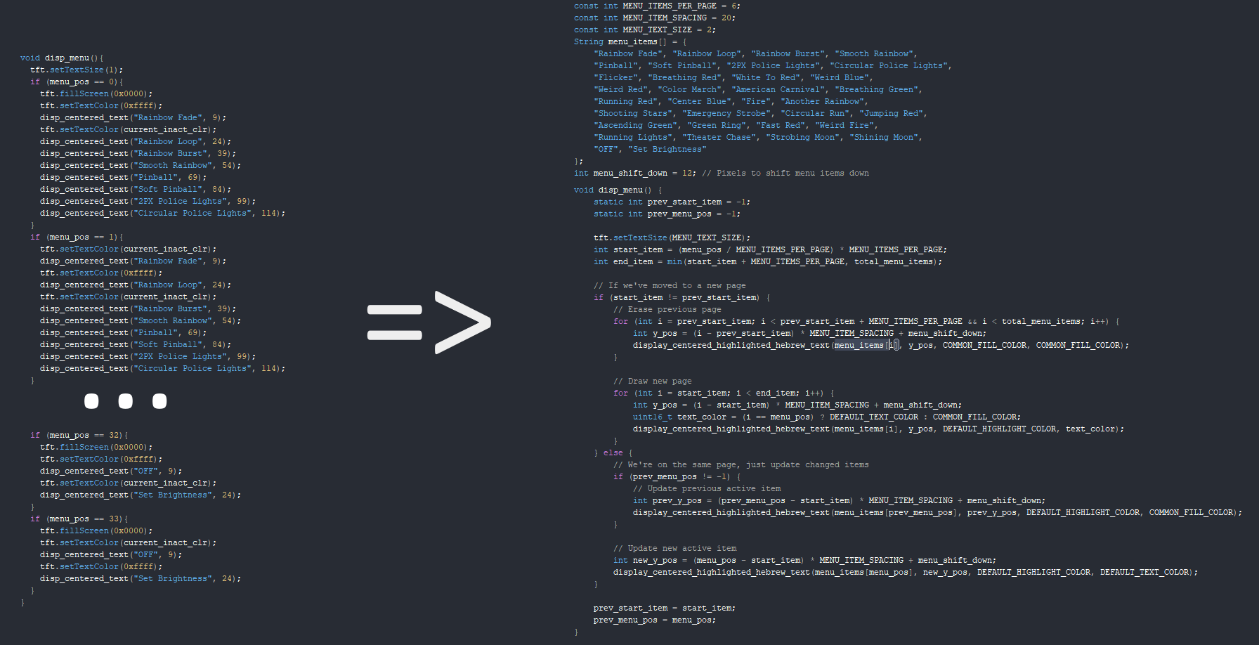
The Addressable RGB LED Strip Controller (The Lantern Project) employed a very basic function to display the menu. To reduce the size of the menu-displaying function and make it easily modifiable in the future, I fed the old menu-displaying function to Perplexity and asked it to optimize it. As you can see, the new menu-displaying function is definitely more sophisticated and upgradeable than the previous one.
Prepare the Development Environment
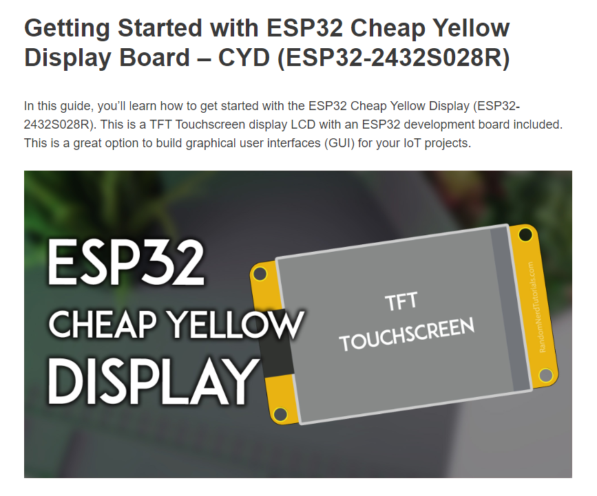
To flash the ESP32 CYD, you need to configure the Arduino IDE, install the necessary libraries, and put the “User_Setup.h” file where it should be. You can read how to do all of that at https://randomnerdtutorials.com/cheap-yellow-display-esp32-2432s028r/
Install the Required Libraries
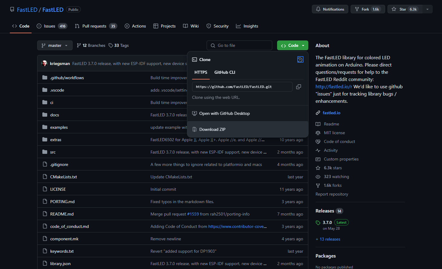
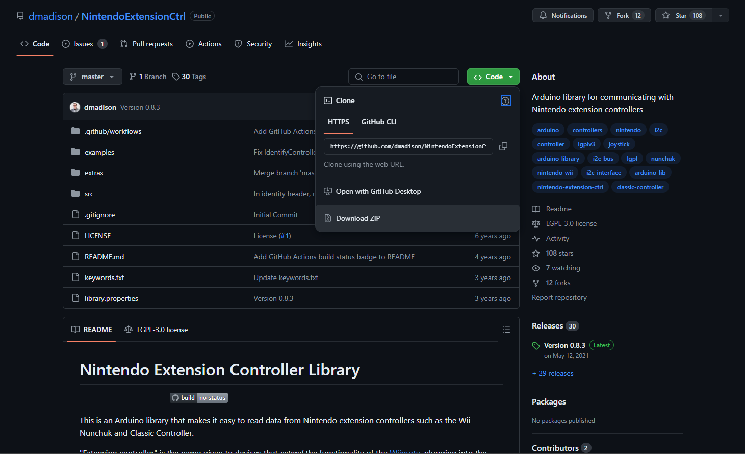
Download the archives with the following libraries:
- FastLED: https://github.com/FastLED/FastLED
- NintendoExtensionCtrl: https://github.com/dmadison/NintendoExtensionCtrl
And then either unpack the content of each archive into the "…\Arduino\libraries" folder or open the Arduino IDE, click on "Sketch" -> "Include Library" -> "Add .ZIP Library…" and select each archive with the library.
Download Firmware
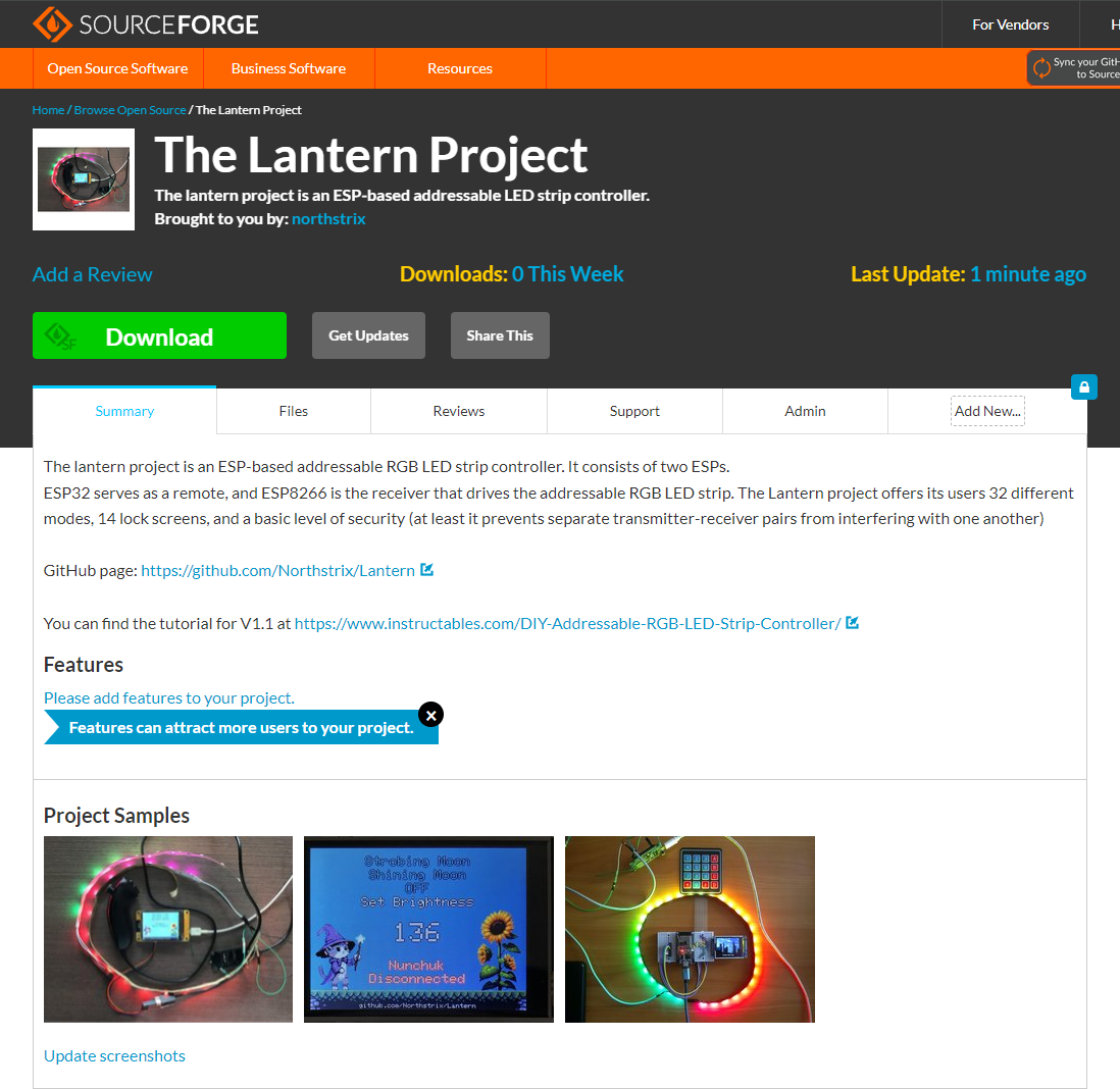
You can download the archive with firmware from one of these sources:
https://sourceforge.net/projects/the-lantern-project/
https://github.com/Northstrix/Lantern
If you only need the firmware, then download the archive from SourceForge. If you also want the project photos, as well as the additional code samples, then download the archive from GitHub.
Install ESP32 Filesystem Uploader
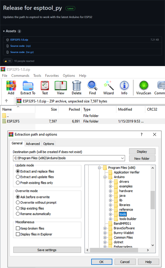
This project requires you to upload the files into the ESP32 built-in flash memory. One of the easiest ways to do so is to install the ESP32 Filesystem Uploader and use it to upload the files.
To install the plugin:
- Download the file called ESP32FS-1.0.zip (https://github.com/me-no-dev/arduino-esp32fs-plugin/releases/);
- Extract the content of the archive into the "...\Arduino\Tools\" folder;
- Restart the Arduino IDE.
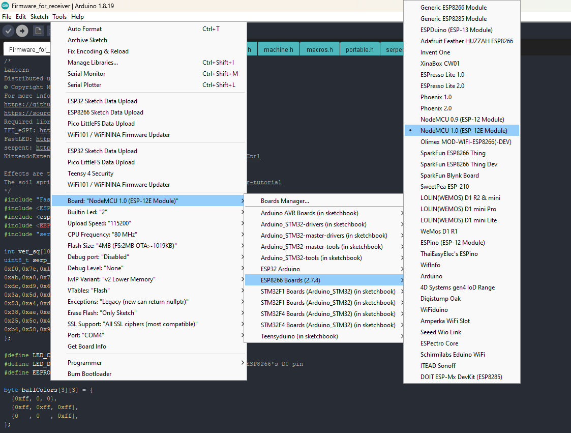
Upload Sprites Into the ESP32 Flash Memory
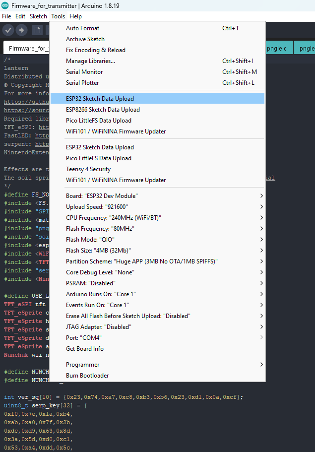
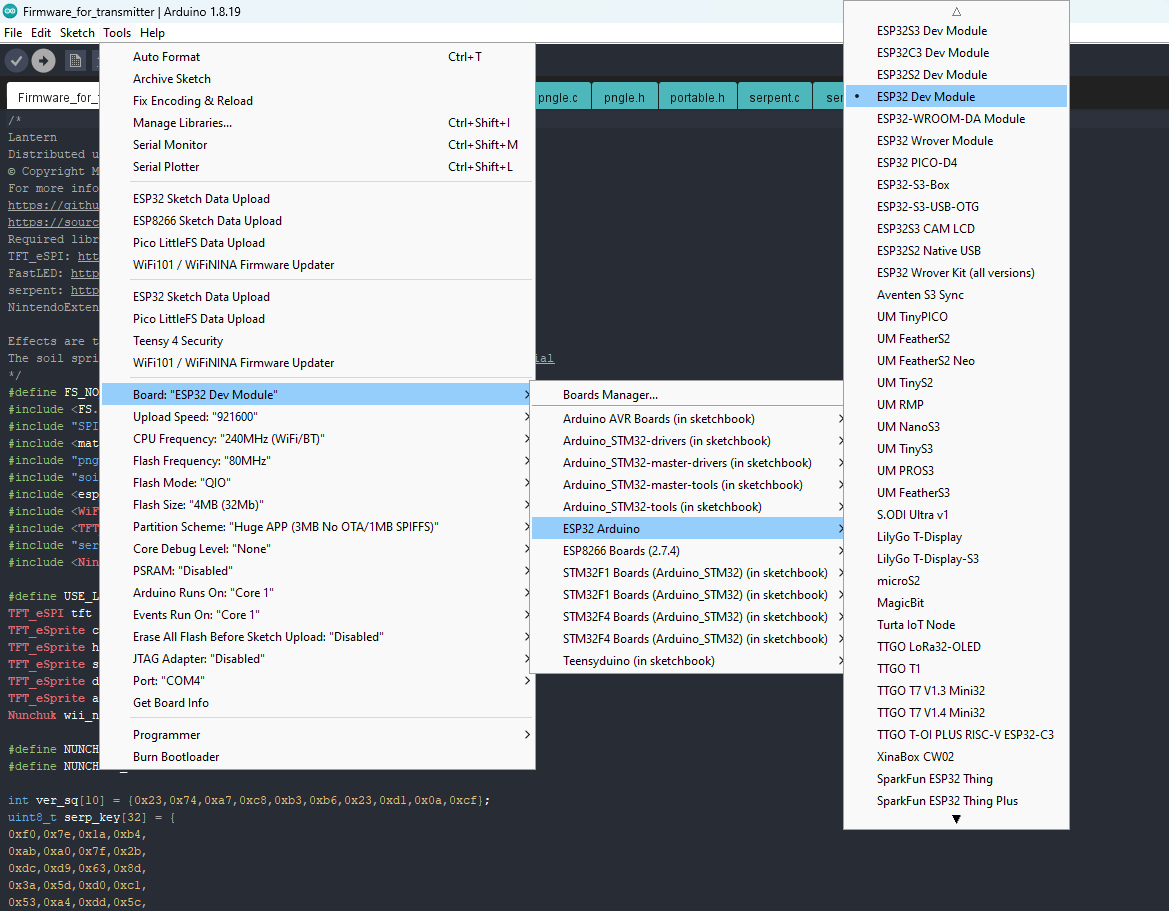
- Open the firmware from the ".../V1.1/Firmware_for_transmitter" folder;
- Connect the ESP32 to the computer and select the corresponding COM port;
- Click Tools -> ESP32 Sketch Data Upload, and then click Yes in the pop-up window.
Clear the ESP8266's EEPROM
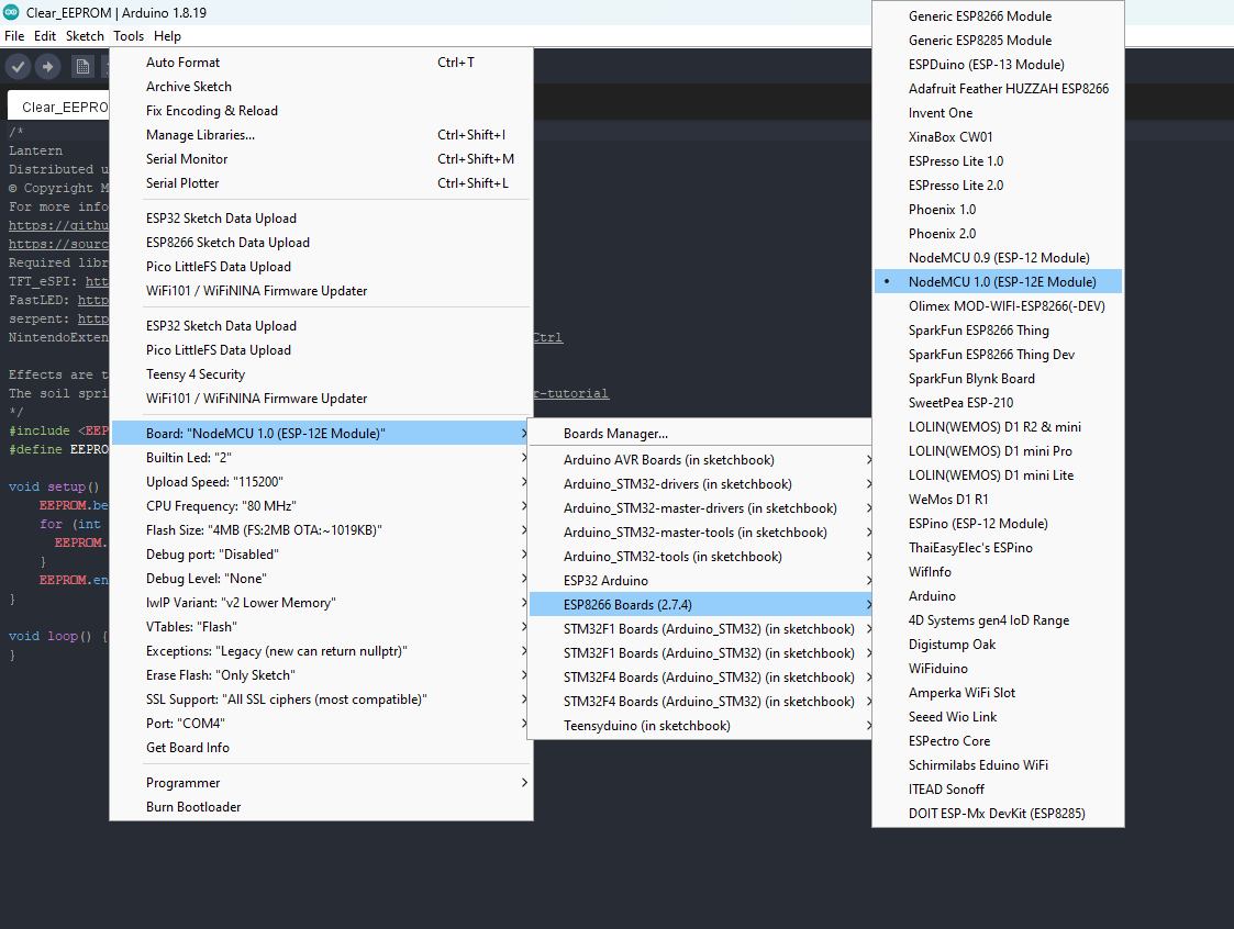
To ensure that Lantern would work as intended - clear the ESP8266's EEPROM before uploading the firmware.
To clear the EEPROM, upload the sketch from the "Clear_EEPROM" folder into the ESP8266 and reboot the board.
Generate Keys
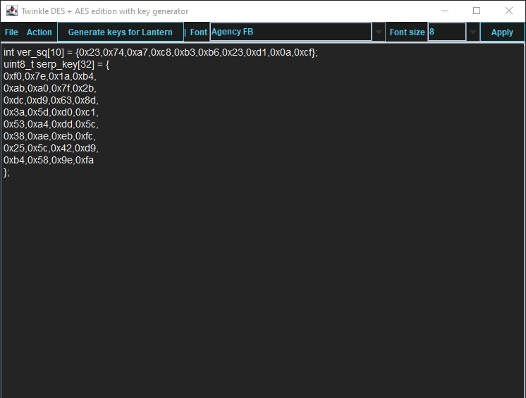
To ensure that an attacker won't be able to hack lantern by simply discovering the receiver's MAC address and to prevent separate transmitter-receiver pairs from interfering with one another: it's crucial to generate the unique keys for each transmitter-receiver pair.
It's entirely up to you how to generate the keys. I can only offer you an option to do so.
I've modified one of my previous projects to work as a random number generator, the generated output seems "random enough" for me, but I haven't run any tests. So, I can't guarantee that it's random.
Use it at your own risk!
To generate the keys - launch gen.exe from the ".../V1.1/Untested RNG" folder and click the "Generate keys for Lantern" button. The background turns from dark gray to light gray when you press that button.
Get the Receiver's MAC Address
To get the receiver's MAC address, upload this code into the ESP8266.
#include <ESP8266WiFi.h>

void setup(){
  Serial.begin(115200);
  Serial.println();
  Serial.println(WiFi.macAddress());
}

void loop(){

}
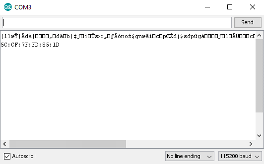
Then open the Serial Terminal, and reboot the board.
If done correctly, you should see the MAC address in the console.
The MAC address of this board is 5C:CF:7F:FD:85:1D
Modify the Firmware
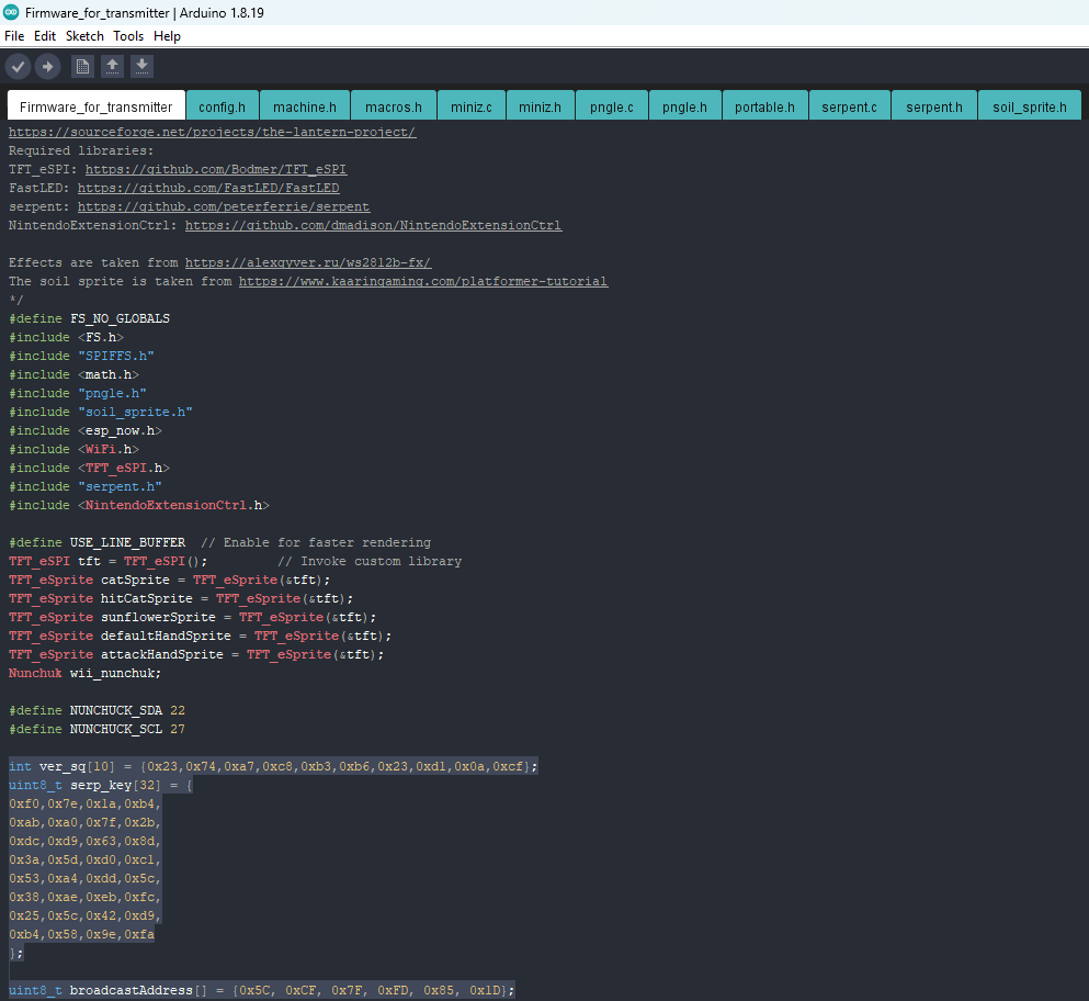
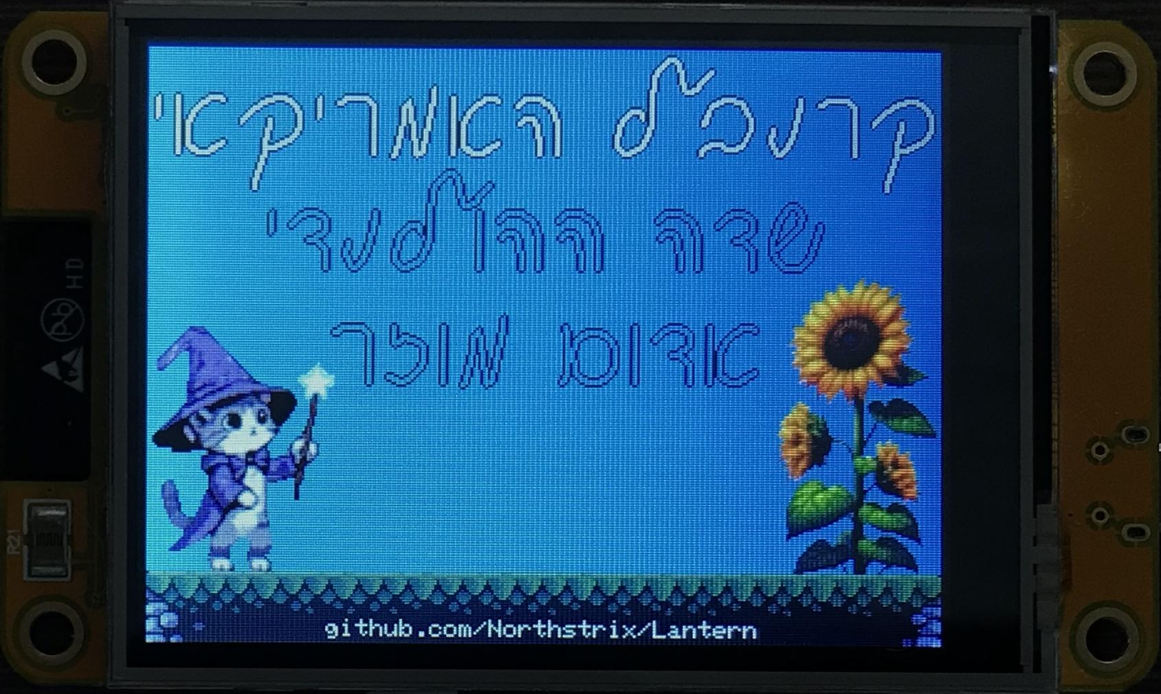
Open the firmware from the ".../V1.1/Firmware_for_receiver" folder, and then open one of the following firmware based on your language preference:
- For English: Navigate to ".../V1.1/Firmware_for_transmitter"
- For Hebrew: Navigate to ".../V1.1/Firmware_for_transmitter_Hebrew"
- Replace the cryptographic keys, as well as the receiver's MAC address in the "uint8_t broadcastAddress[] = {0x5C, 0xCF, 0x7F, 0xFD, 0x85, 0x1D}; // Receiver's MAC address" line in the transmitter's firmware. You can also change the background color by modifying the value defined in the "COMMON_FILL_COLOR" (as well as the other parameters).
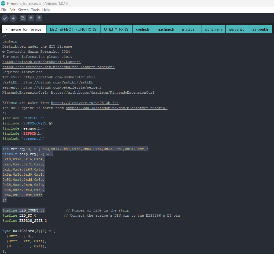
- Replace the cryptographic keys, as well as the number of LEDs in the strip in the " #define LED_COUNT 32 // Number of LEDs in the strip" line in the receiver's firmware.
Flash ESP8266
Upload the modified firmware from the ".../V1.1/Firmware_for_receiver" folder into the ESP8266.
Flash ESP32
Upload the modified transmitter's firmware into the ESP32.
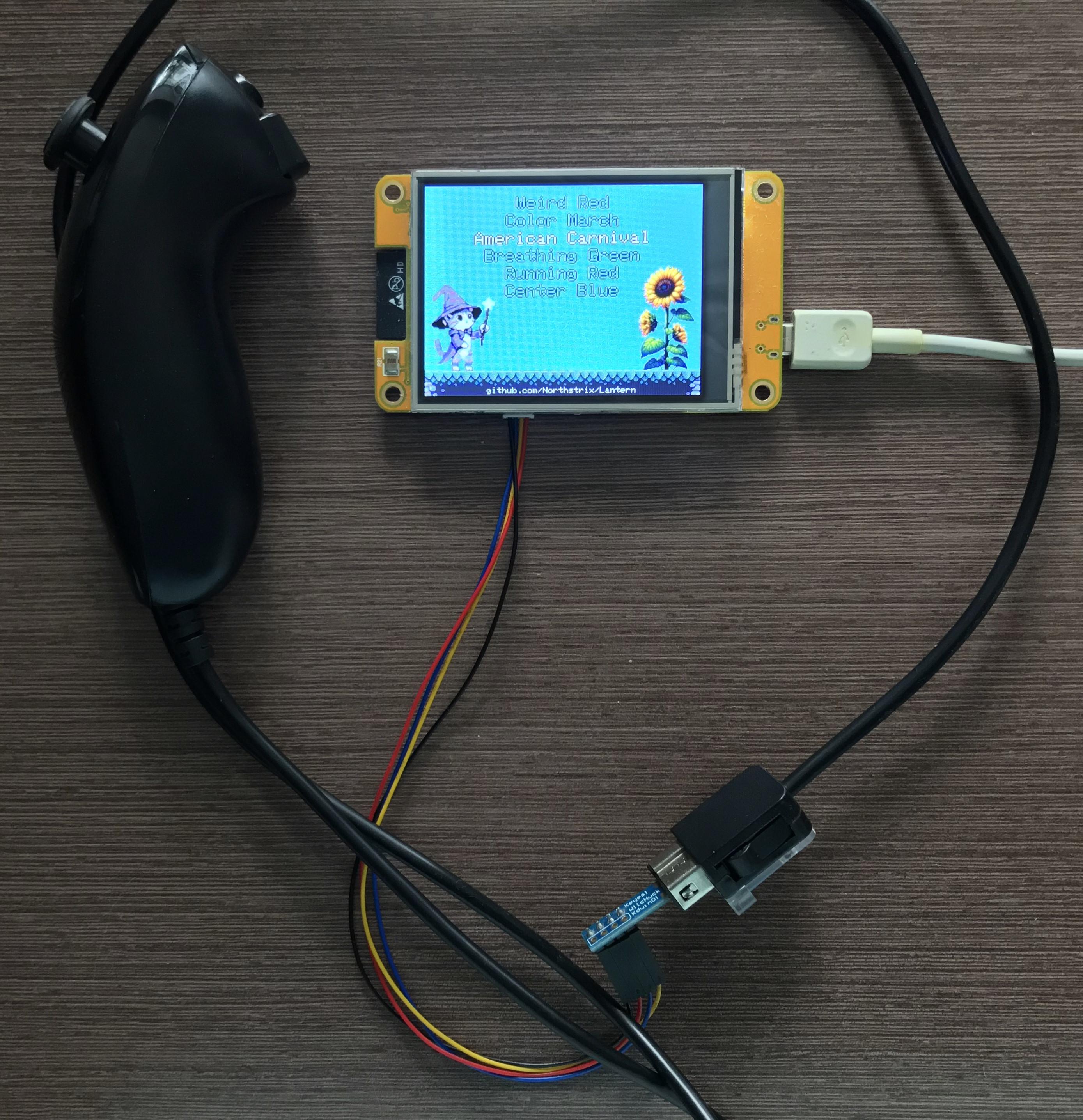
Assemble the Transmitter
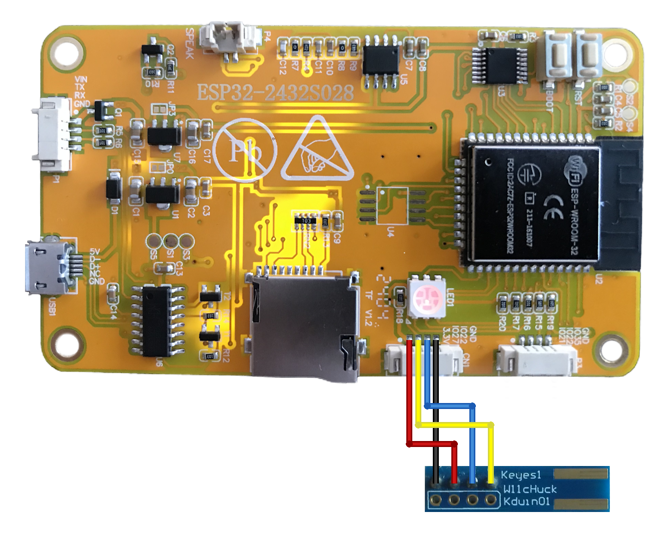
Connect the Nunchuk adapter to the ESP32 CYD, and then connect a Nunchuck to it.
Assemble the Receiver
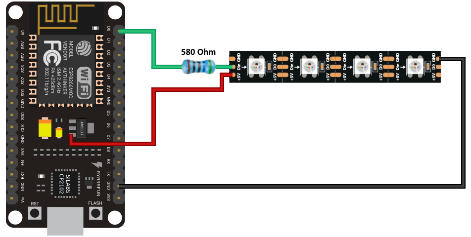
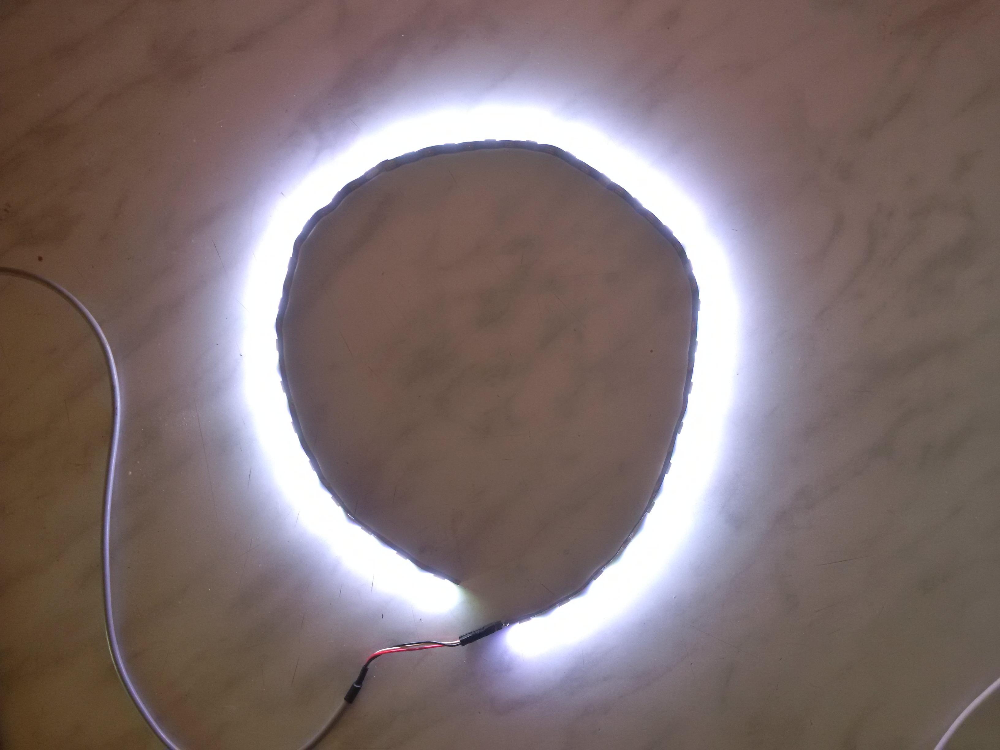
Connect the WS2812 LED Strip to the ESP8266 with its DIN pin connected via the 580 Ohm resistor.
Power Up the Receiver and the Transmitter
Power up the receiver and simply leave it. There are no controls on it anyway.
Power up the transmitter, and press either the "C" or "Z" button on the Nintendo Wii Nunchuk.
Versions of a Cat
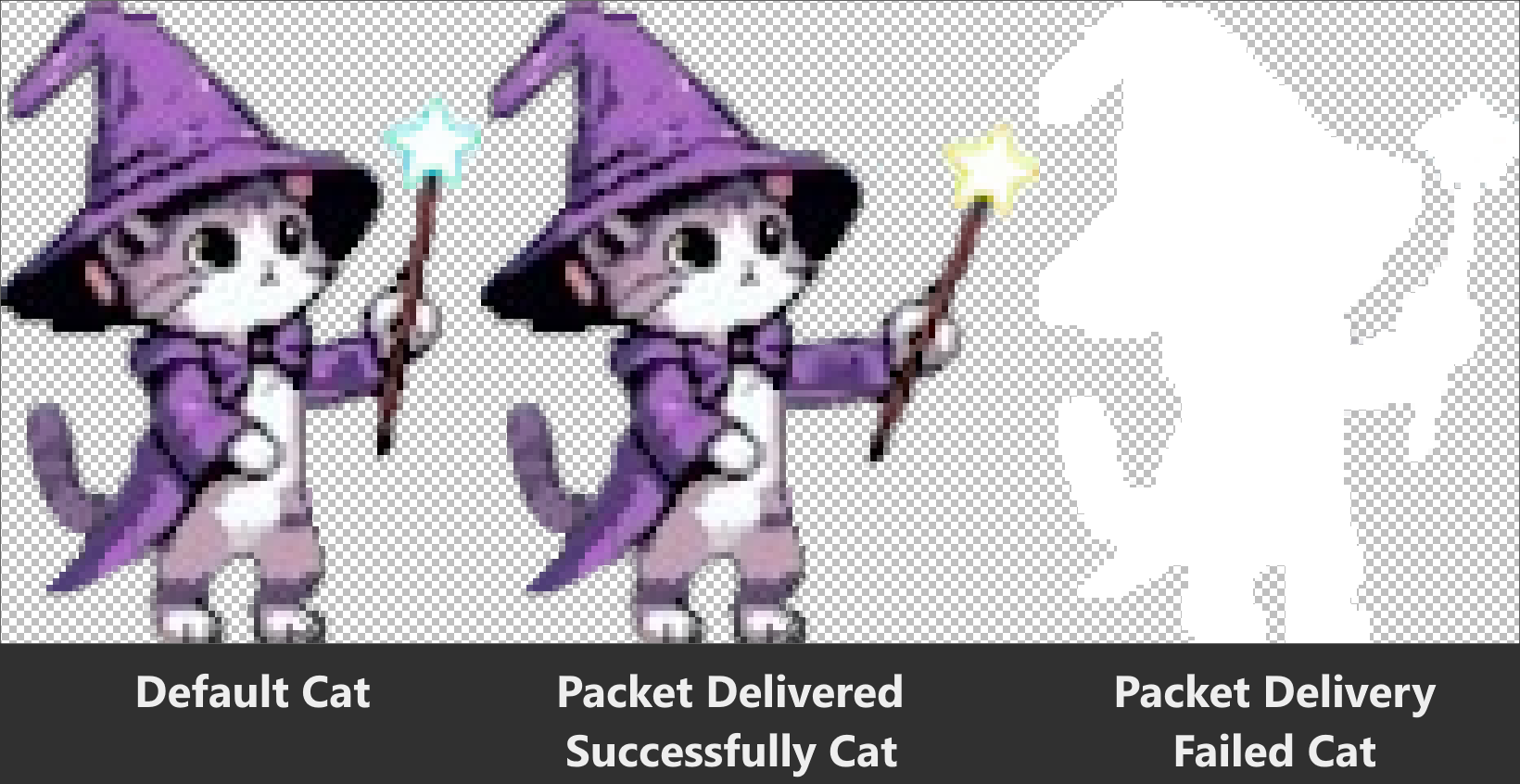
To make this device more convenient, I made the cat indicate whether a packet was delivered or not.
By default, the cat stands still.
When the packet is delivered successfully, the cat extends the hand with the wand, indicating that the packet delivery "magic" is done.
When the cat turns white as if it's hit, then the packet delivery has failed.
Choose Mode
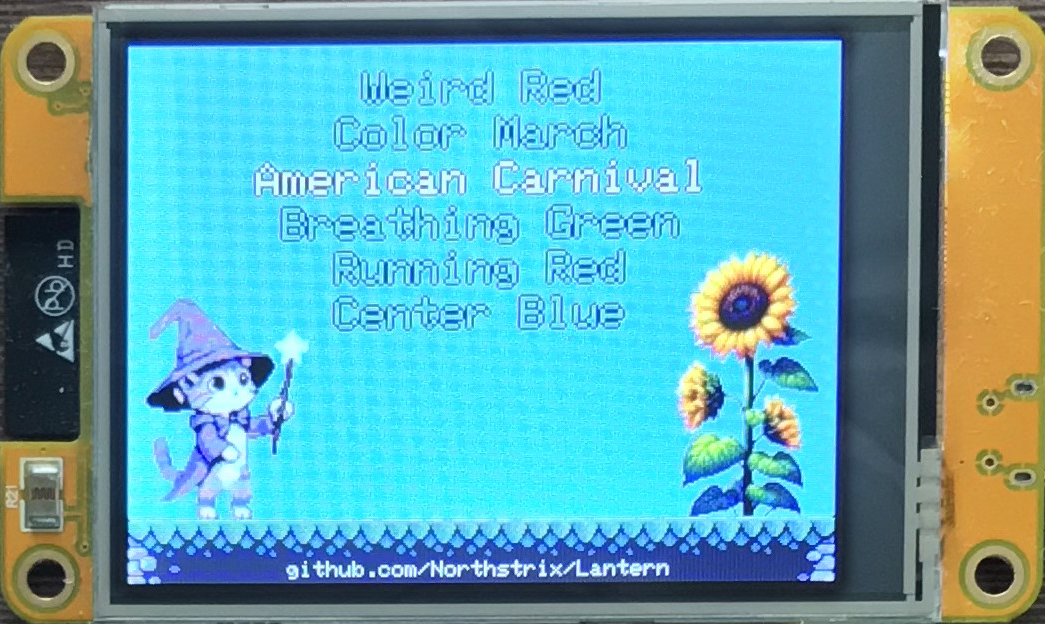
Once you've flashed both boards, assembled the circuits, and powered up both the receiver and the transmitter, you can start using the controller.
Move the Nunchuck stick up and down to go through the menu, and press any button ("C" or "Z") on the Nintendo Wii Nunchuck to set the selected mode to the LED strip.
The GIFs with some of the modes are shown in the steps 25 - 42;
Set Brightness
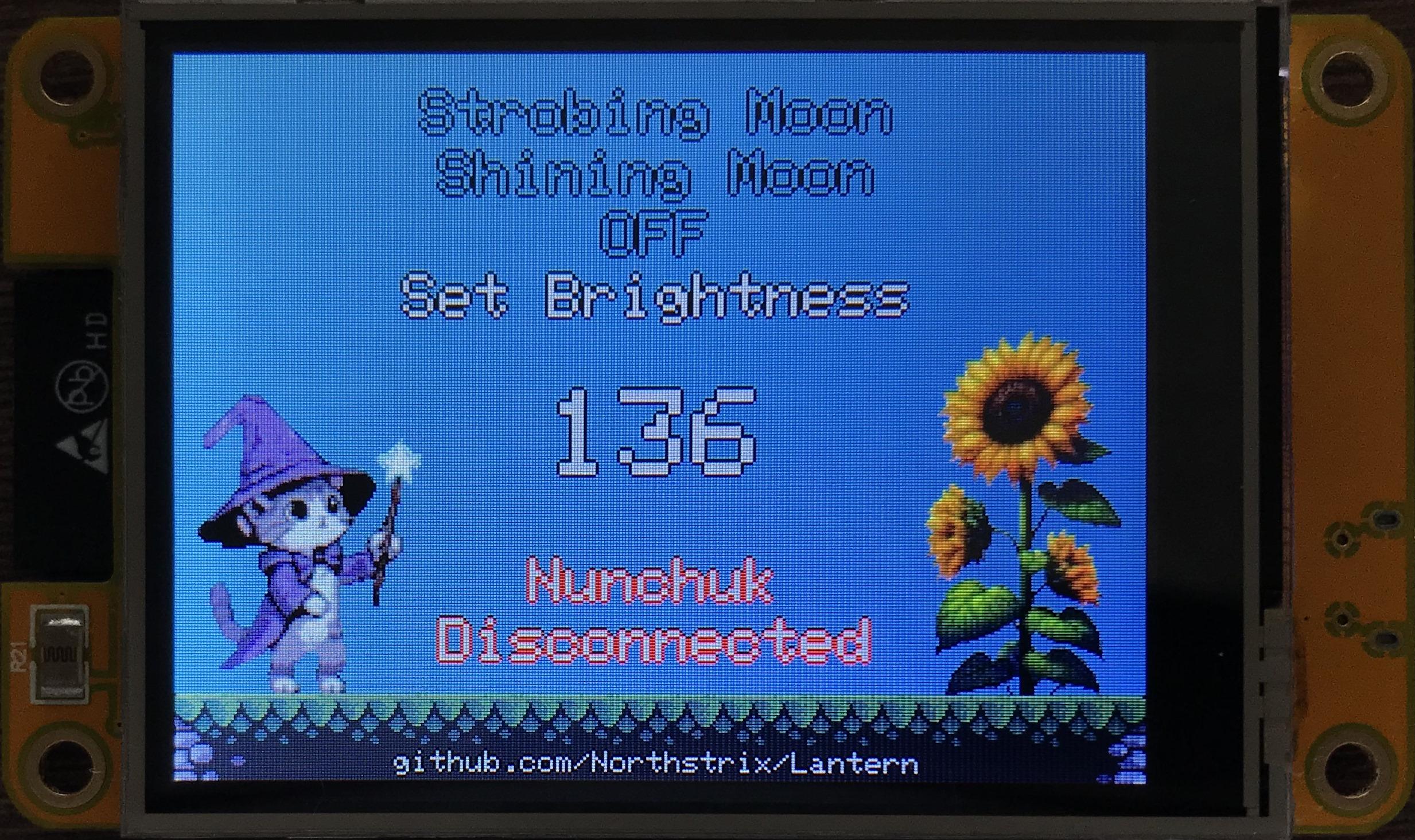
To change the brightness of the LED strip, select the "Set Brightness" line and move the stick to the left and to the right to change its value. Press any button on the Nunchuk to set the brightness to the strip.
The receiver stores the brightness value in its EEPROM, so it won't be lost even if you turn the device off.
The transmitter, on the other hand, only stores the brightness value in its RAM, so it'll be lost as soon as you remove the power from it. But don't worry about it. The value that matters (after the brightness is set) is the one that's stored in the receiver's EEPROM.
Rainbow Fade
Rainbow Loop

Smooth Rainbow
2PX Police Lights
Circular Police Lights

Flicker
White to Red

Color March

American Carnival
Fire

Shooting Stars

Emergency Strobe
Circular Run
Jumping Red
Ascending Green

Green Ring

Theater Chase
Strobing Moon

Shining Moon
The shining moon mode sets each LED in the strip to the maximum brightness.
I suggest you don't turn it on for long because it may damage the strip.
Enjoy the Result
Lantern V1.1 is a convenient, open-source device that enables you to control an addressable RGB LED strip at a distance of up to 650 feet (200 meters). In addition to that, it's also easy to assemble.
Lantern's source code is distributed under the MIT license. That grants you the freedom to customize, adapt, and modify Lantern according to your needs and preferences. In other words, you can create your own version of Lantern or use it as a starting point for building new projects without the need for external permission.
If you make this device press, please press the "I Made It" button and share a couple of photos of your Lantern.