DESIGN AND BUILD a WIRELESS LASER ENGRAVER CUM PEN PLOTTER USING FUSION 360 AND 3D PRINTING
by patrick panikulam in Workshop > CNC
30353 Views, 173 Favorites, 0 Comments
DESIGN AND BUILD a WIRELESS LASER ENGRAVER CUM PEN PLOTTER USING FUSION 360 AND 3D PRINTING
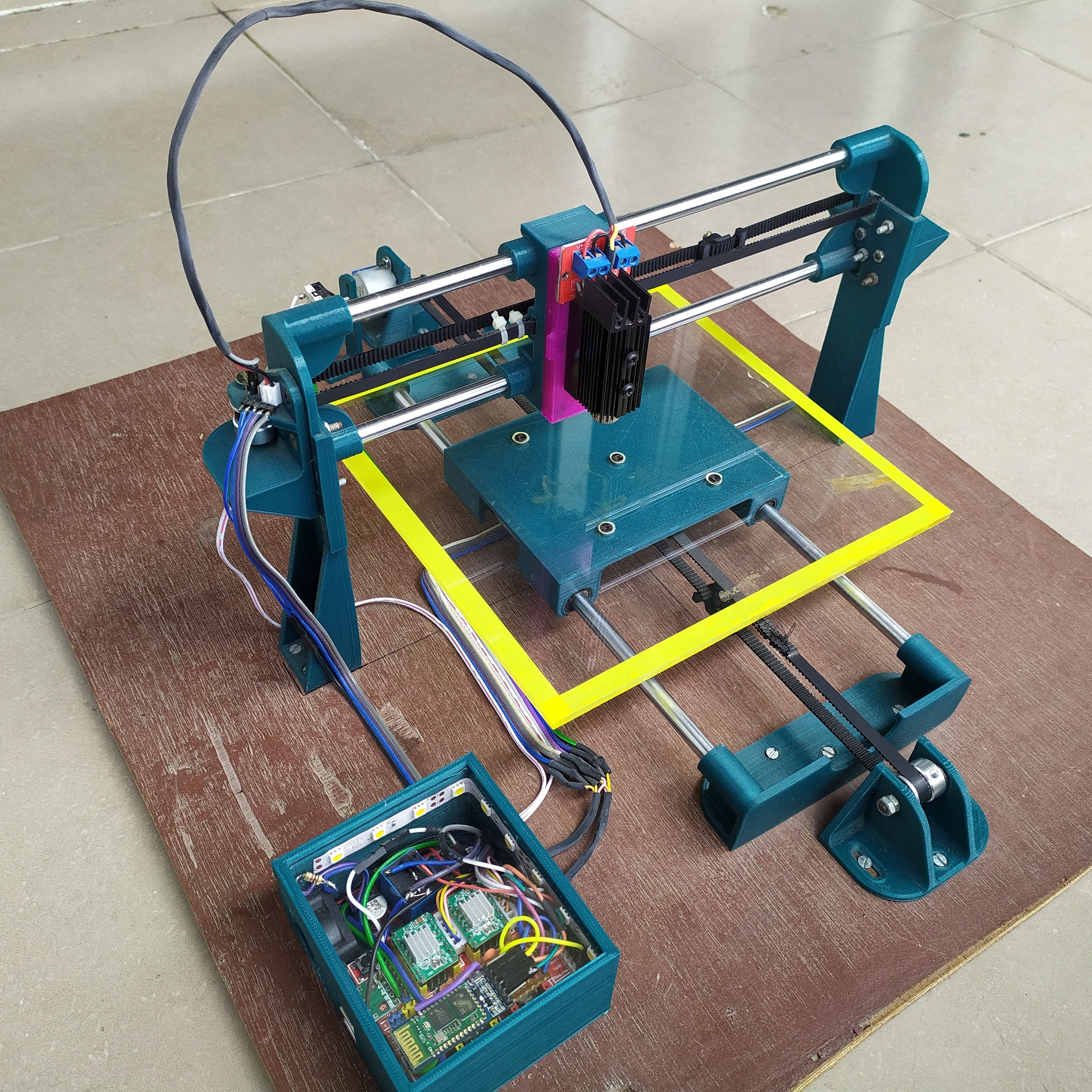

A couple of months back while checking out a few laser engravers on aliexpress, I came across some USB powered laser engravers, It was awesome that these could engrave on a variety of materials and also cut out shapes and designs from sticker sheets and paper and doing all this powered by a 5V USB supply. But the downside of these engravers was that they had a small work area, in most cases just 40mm X 40mm which is definitely way too small for my needs.
So I thought why not design and 3D print my own laser engraver from scratch. I started the designing process in FUSION 360 while keeping in mind all the 3D printing tolerances. And finally came up with something really cool. Along the way, I decided to make the laser holder modular so that I can easily replace the laser with a pen or marker for pen plotting. I also added a Bluetooth connectivity feature so that wired connection between your PC and the engraver can be eliminated while transmitting G codes.
So this instructible basically shows how you can make one kind of CNC machine using another kind of CNC machine ;-)
SPECIFICATIONS:-
1. A work area of 200 X 162 mm
2. 1000 mW laser module
3. Runs on a USB power source (5 volts)
4. Auto homing feature.
5. Bluetooth communication between the laser engraver and PC.
6. PWM control of the laser.(helps in producing different shades of black when engraving portraits)
7. 102.4 steps per mm resolution
8. The machine can engrave, cut and draw on different materials.
9. Switchable laser and pen modules.
10. Magnetic module holder for easy switching.
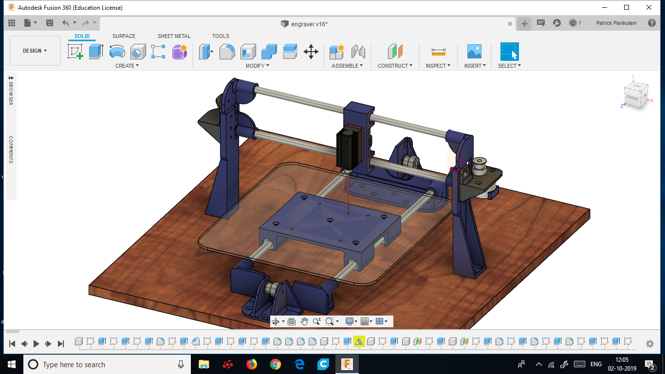
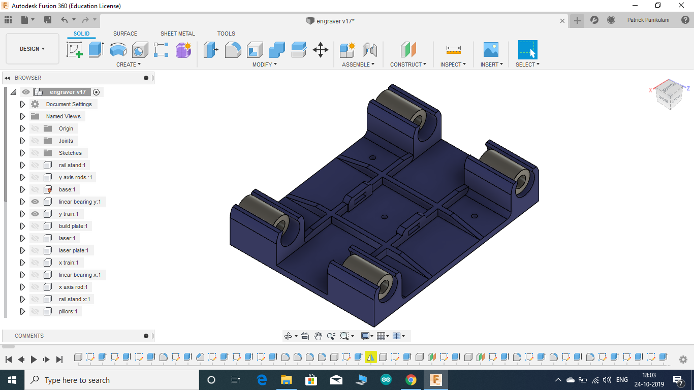
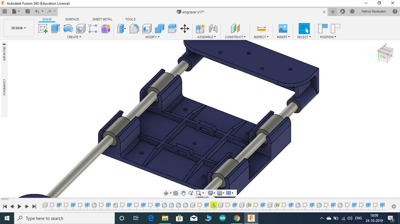
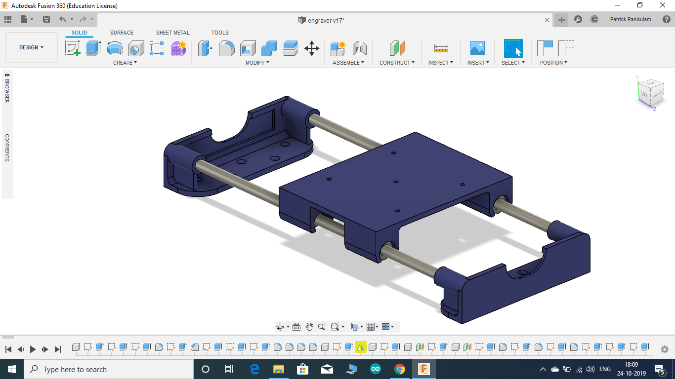
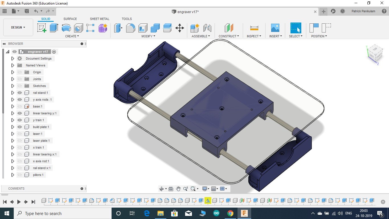
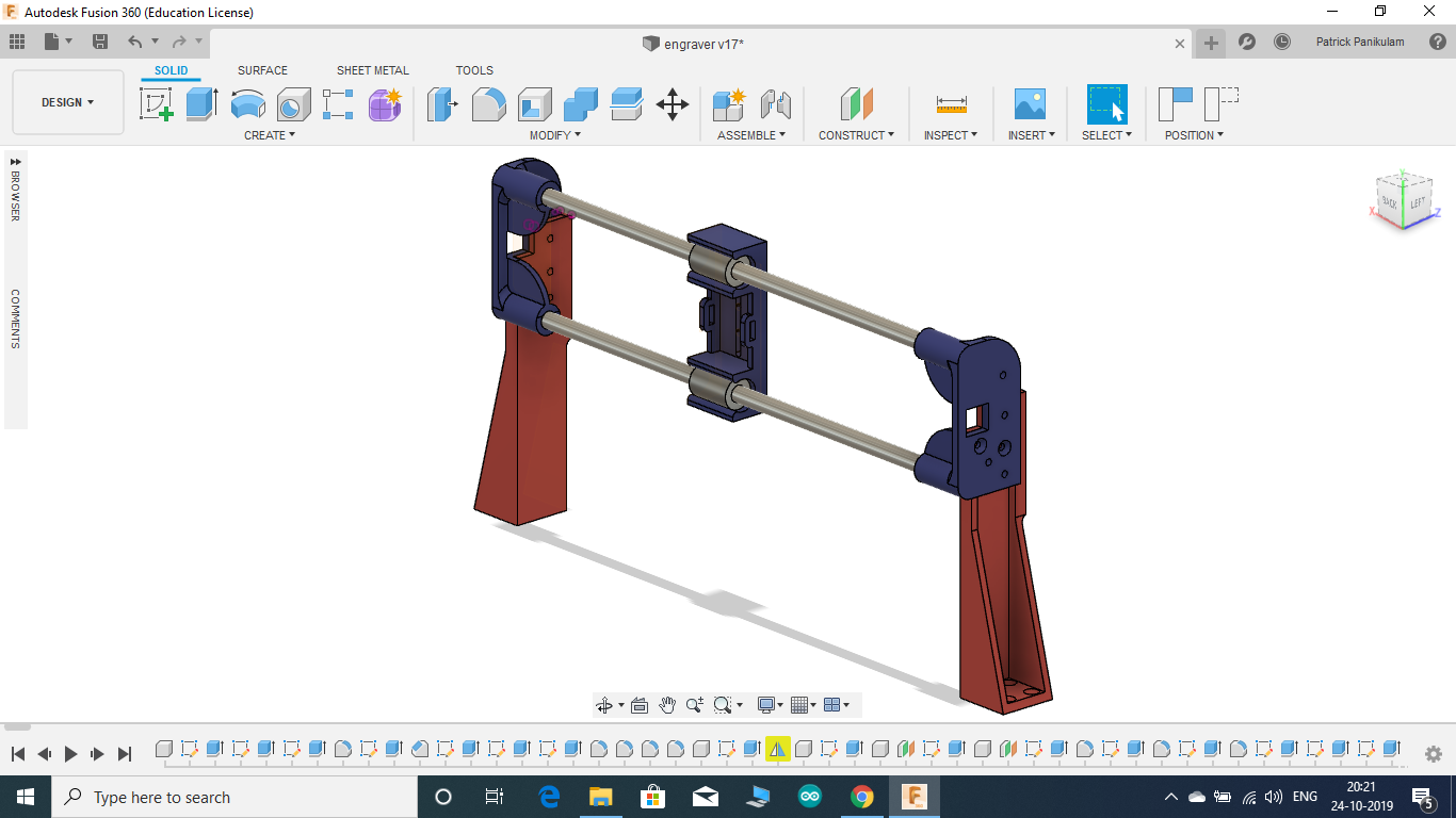
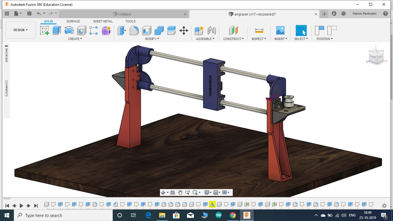
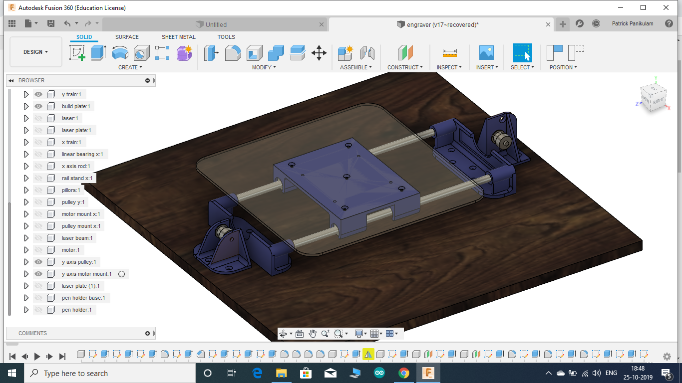
DESIGNING THE LASER ENGRAVER IN FUSION 360
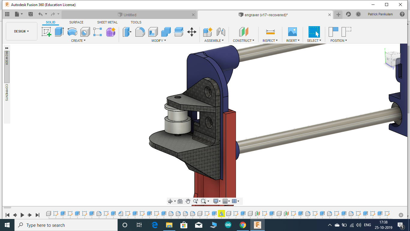
.png)
.png)
.png)
.png)
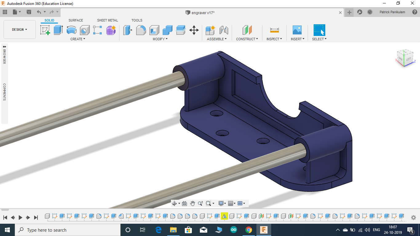
FUSION 360 is one of those amazing platforms which allows you to convert those design ideas inside your head into reality. It really helps in expressing your idea about something to others. It's really easy to learn and use. Assembly of the components can be done easily and it helps in the validation of your design by checking for collisions and other problems
I started by designing the base and the Y-axis smooth rod holders. Since the holders consist of two identical components, the mirror feature in fusion 360 got the job done easily. The mirror feature has been used multiple times in designing this laser engraver. Unlike other cad software, one cool thing about fusion 360 is that it allows the designing of multiple components on the same screen with reference to other components, ie the model can be designed in an assembled manner.
The hight of the X-axis guide rails depends on the focal range of the laser you are using. Just make sure that the height of the laser is within that range. The final focusing of the laser beam can be done by adjusting the lens on the laser.
Fusion 360 also allows us to choose the appearance and material of the components so that your final design looks like the real thing. Fusion 360 also lets us convert and save the designed components directly in STL format which makes it easier for the next stage of 3D printing.
I will be sharing the Fusion 360 file of the assembly here,you guys can modify it according to your needs.
Downloads
COMPONENTS, MODULES AND TOOLS REQUIRED:-
MODULES AND COMPONENTS:
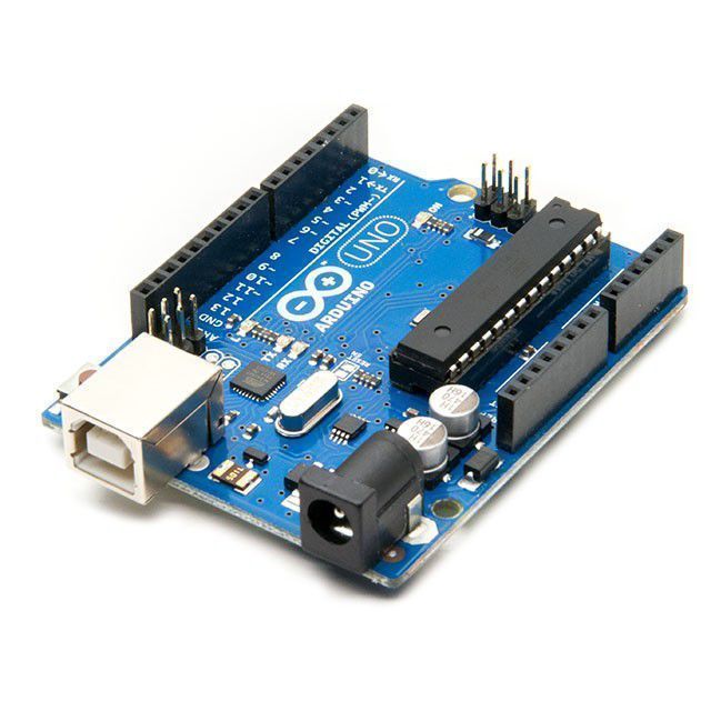
- 1 X Arduino UNO (Aliexpress)
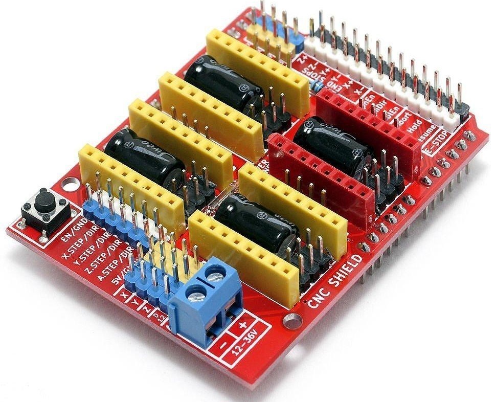
- 1 X CNC Shield v3 (Aliexpress)
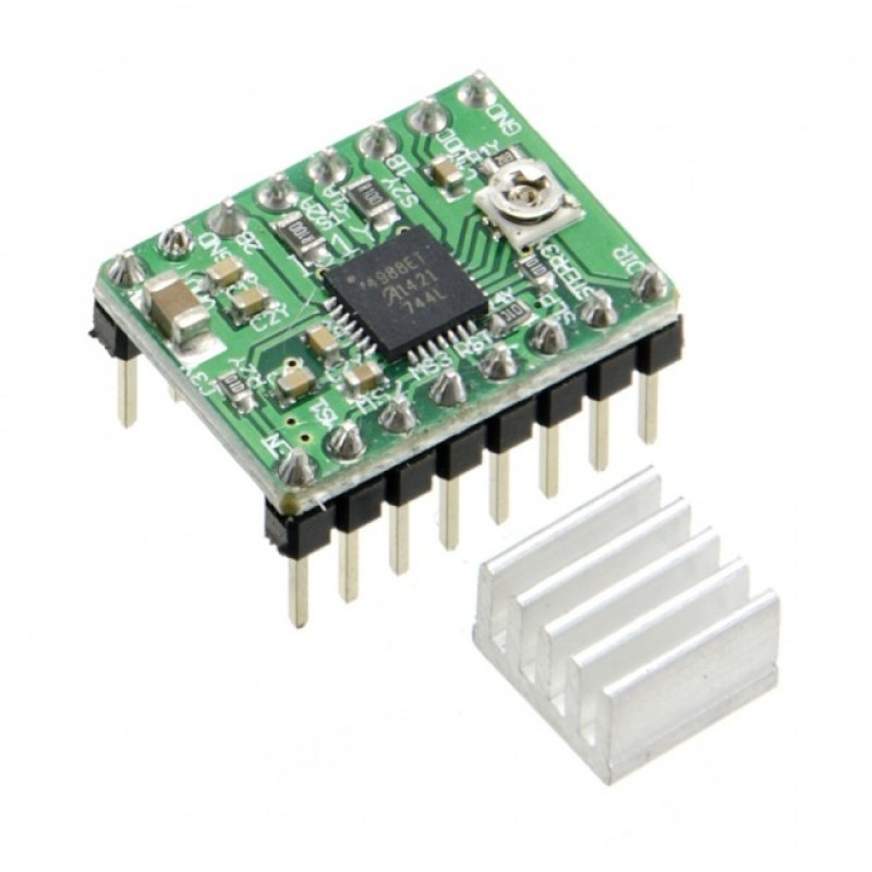
- 2 X A4988 stepper motor driver (Aliexpress)
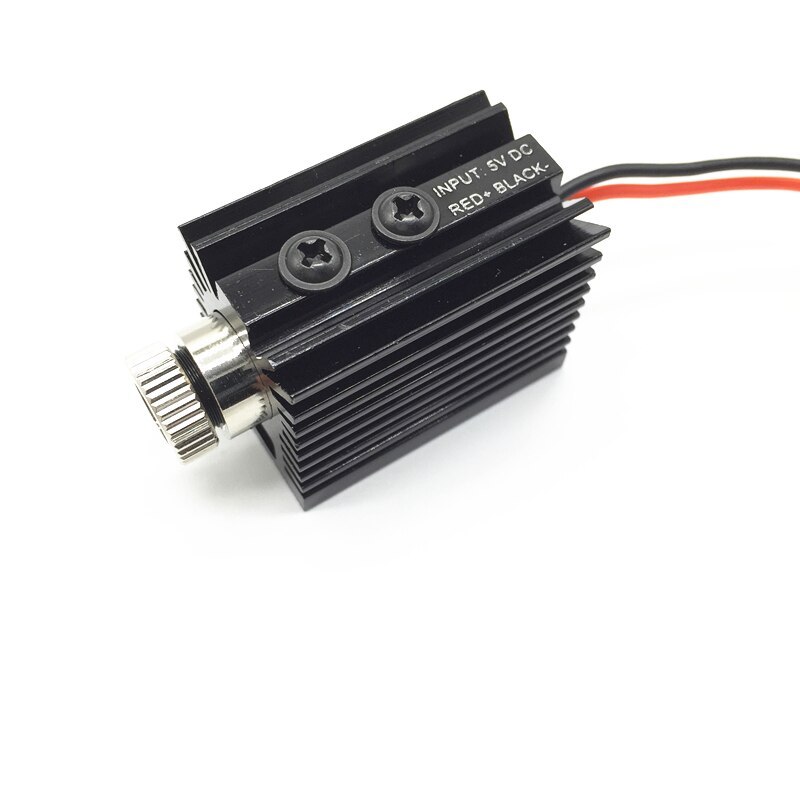
- 1 X 1000 mW laser module (Aliexpress)
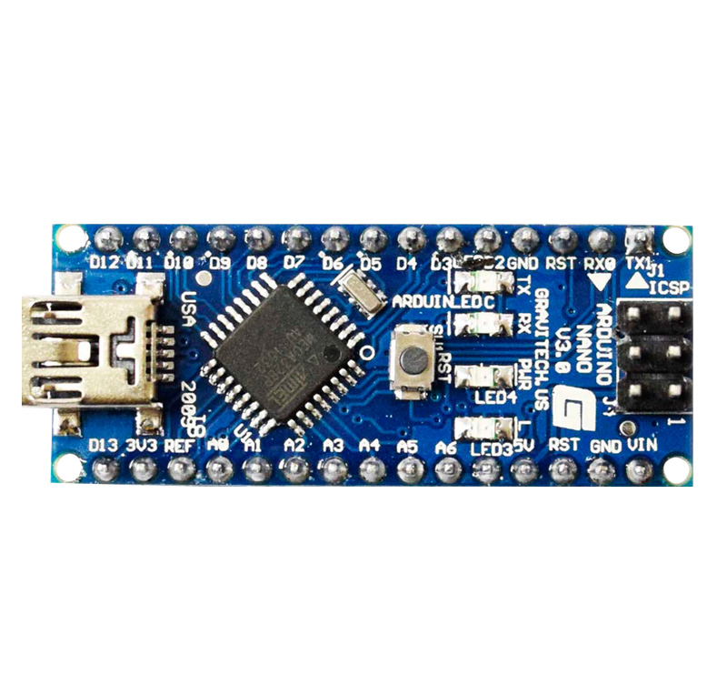
- 1 X Arduino Nano (Aliexpress)
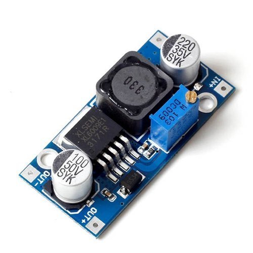
- 1 X XL6009 Boost converter (Aliexpress)
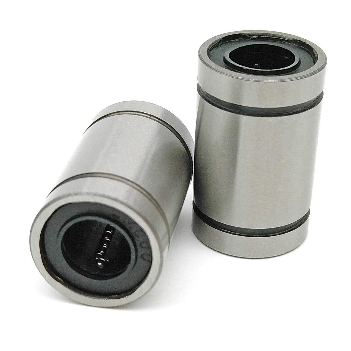
- 6 X LM8UU linear ball bearings (Aliexpress)
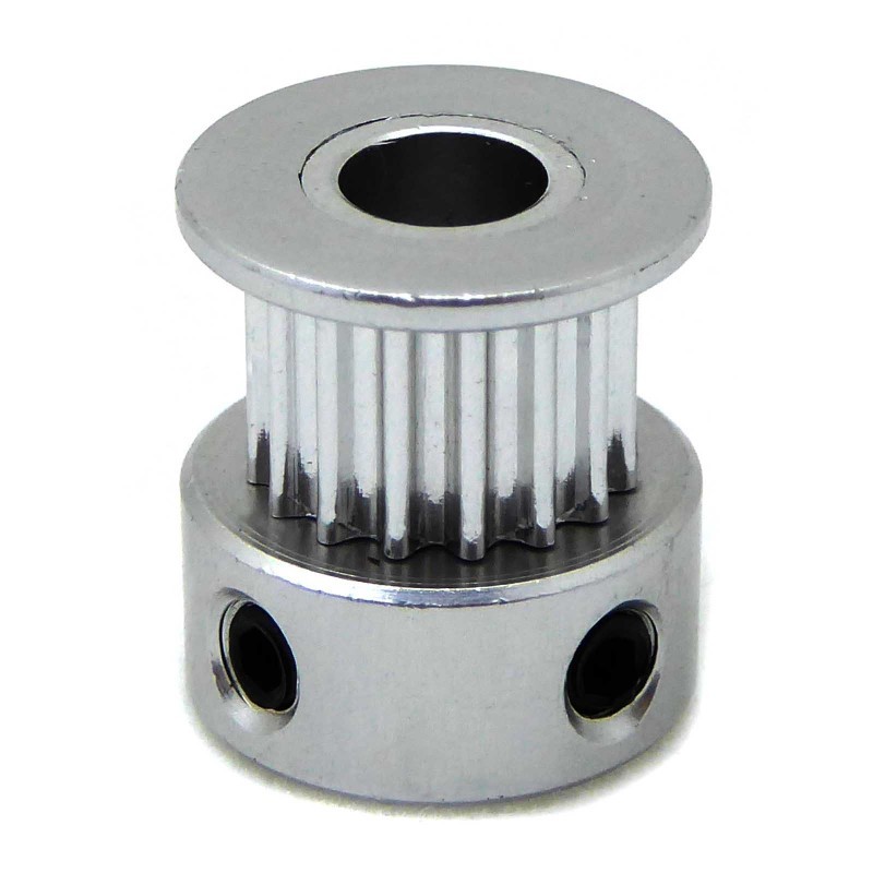
- 4 X 16 teeth 2GT timing pulley (Aliexpress)
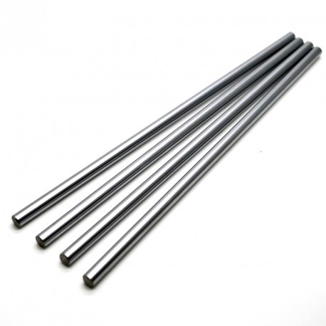
- 4 X dia-8mm, length-300mm smooth rods (Aliexpress)
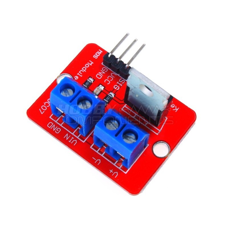
- 1 X IRF520 Mosfet module (Aliexpress)
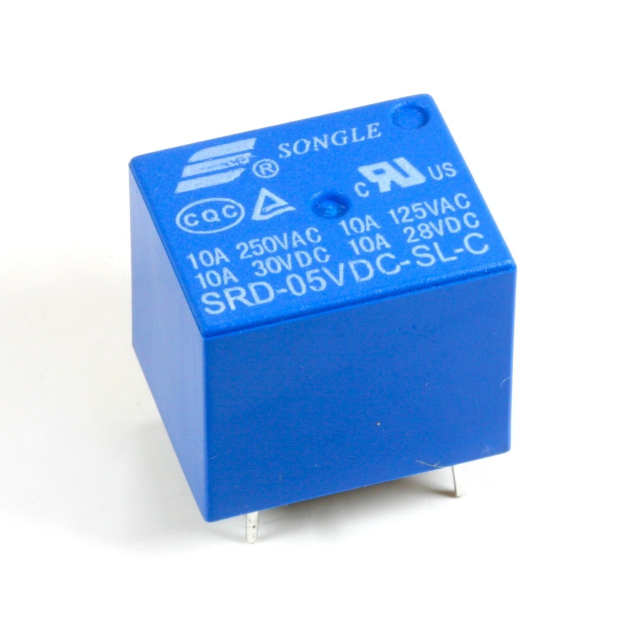
- 1 X 5-volt relay (Aliexpress)
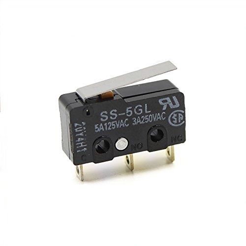
- 2 X Limit switches (Aliexpress)
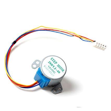
- 2 X 28BYJ-48 stepper motors (Aliexpress)
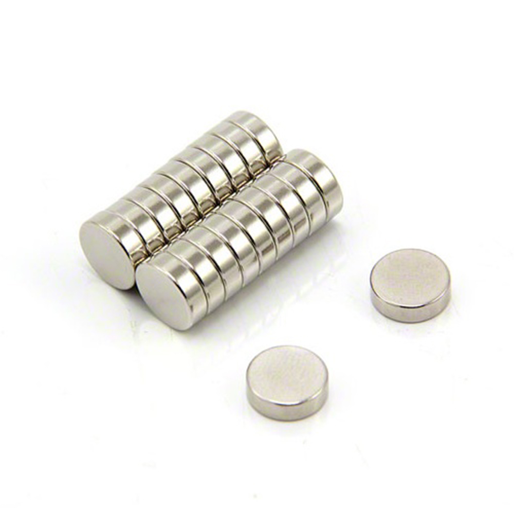
- 18 X 5mm x 3mm neodymium magnet (Aliexpress)
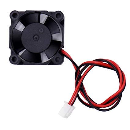
- 1 X 30*30mm 5 volt cooling fan (Aliexpress)
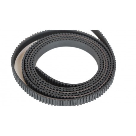
- 2 X GT2 6mm timing belt 1 meter (Aliexpress)
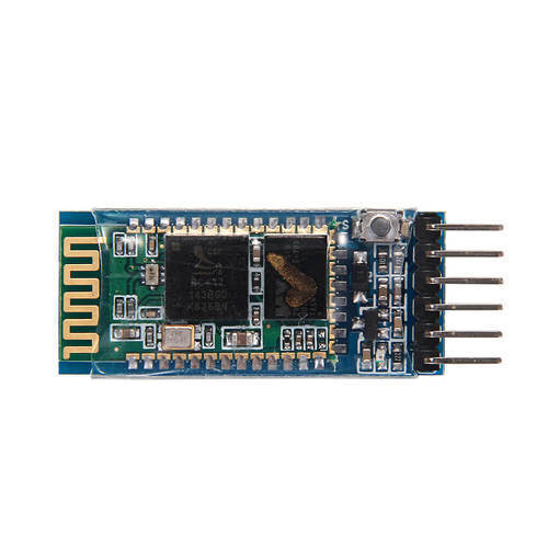
- 1 X HC-05 Bluetooth module (Aliexpress)
- 1 X SG90 servo motor (Aliexpress)
- 2 X Screw terminal blocks (Aliexpress)
- Heat shrink insulation
- Superglue
- Cable ties
- M3 30mm
- M3 12mm bolts
- M4 40mm
- M3 nuts
- M4 nuts
- 8mm plywood board of 48 X 42 cm
- 5mm transparent Acrylic sheet of 22 X 22 cm
- 5 volt USB phone charger and MicroUSB cable
TOOLS:
- Sandpaper
- Small triangular file
- Screwdrivers
- soldering iron
- Hand saw
- Pliers
- Lighter
- Scissors
- Wire cutters
- Hand held rotary tool
PARTS TO BE 3D PRINTED :-
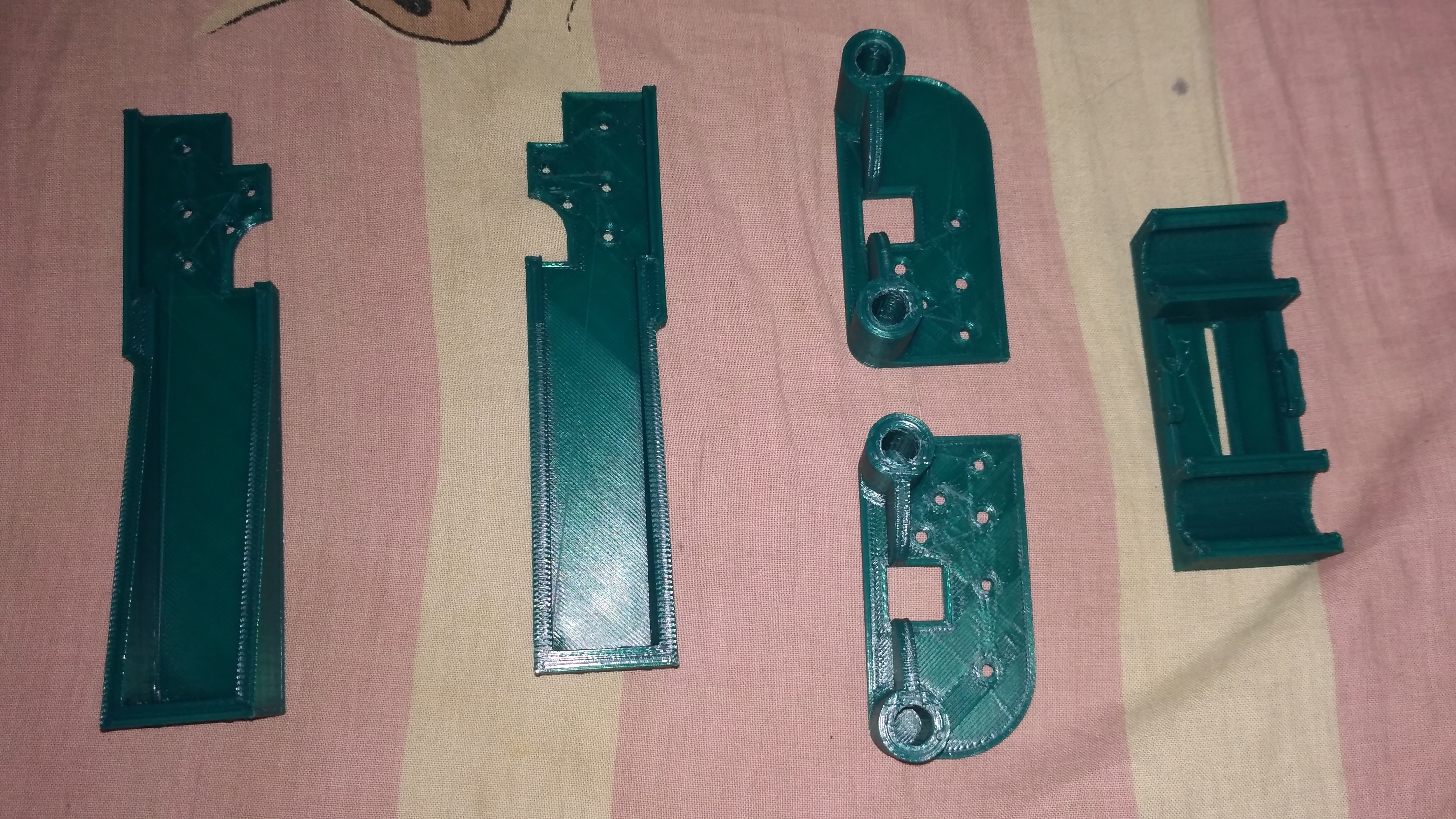
The STL files of all the parts to be 3D printed are uploaded here.
All the parts are designed such that they can be easily 3D printed without supports.
I used a TEVO tarantula 3D printer
- Material : PLA (dark green)
- Layer height : 0.3mm
- Infill : 40%
- wall thickness: 0.8mm
- Top/bottom thickness : 0.9mm
Downloads
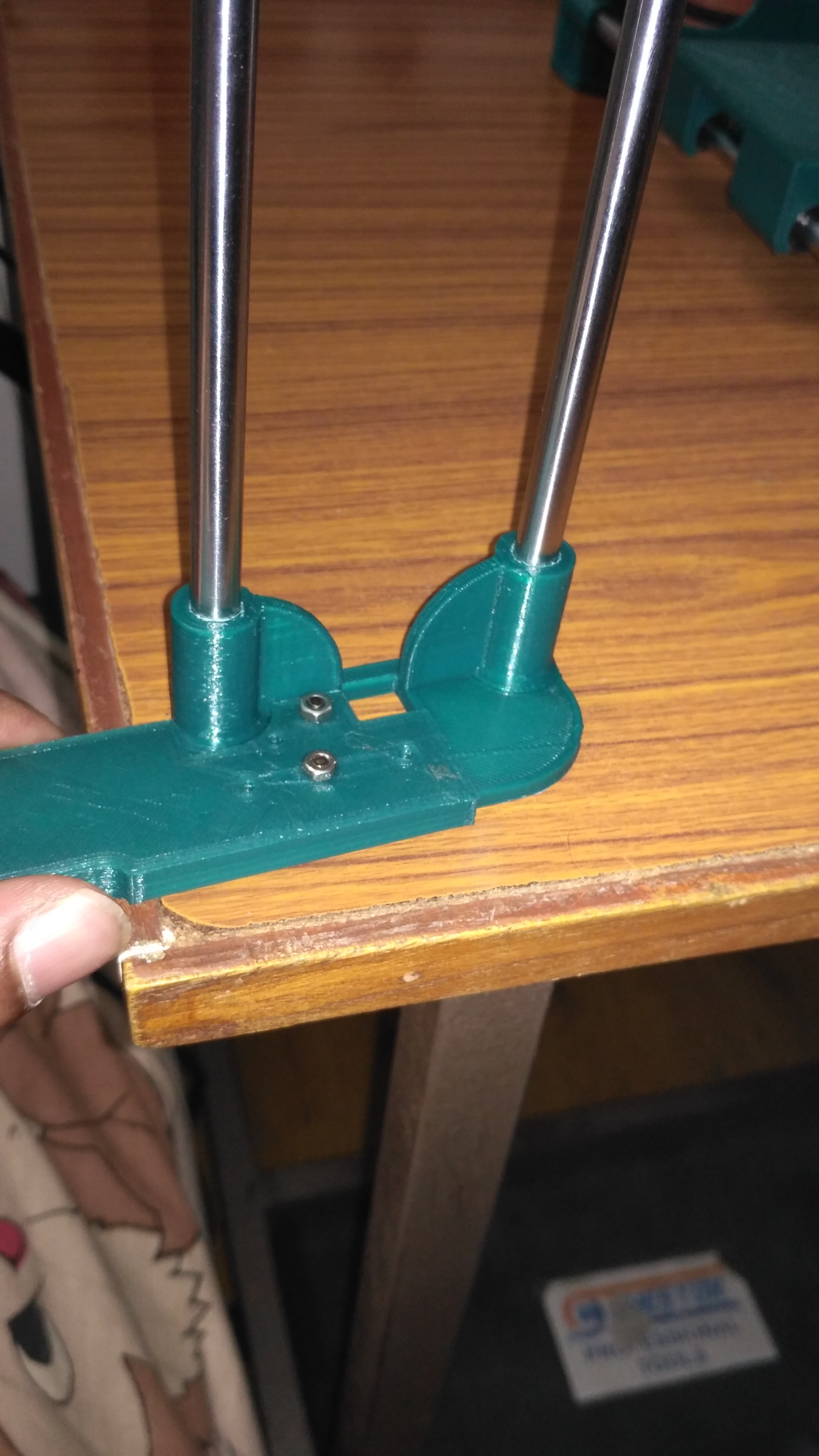
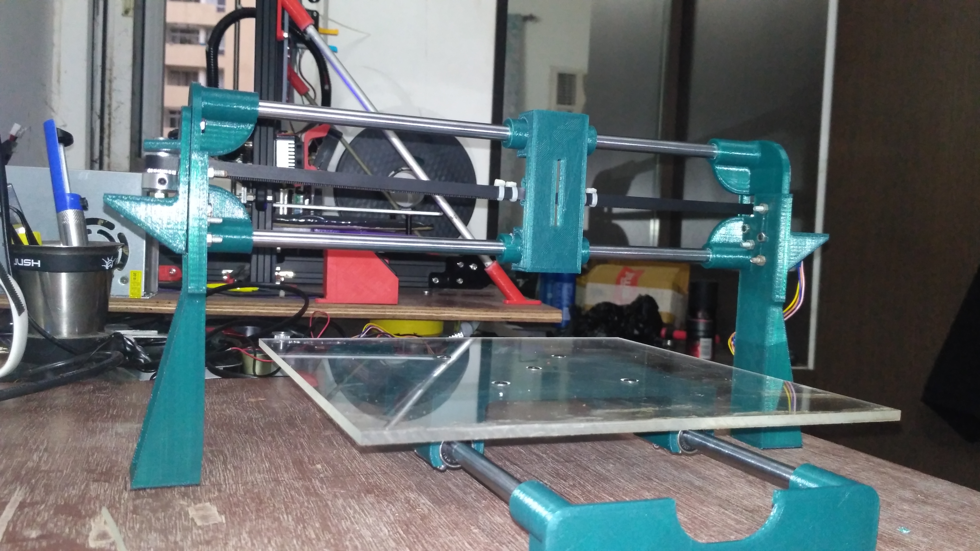
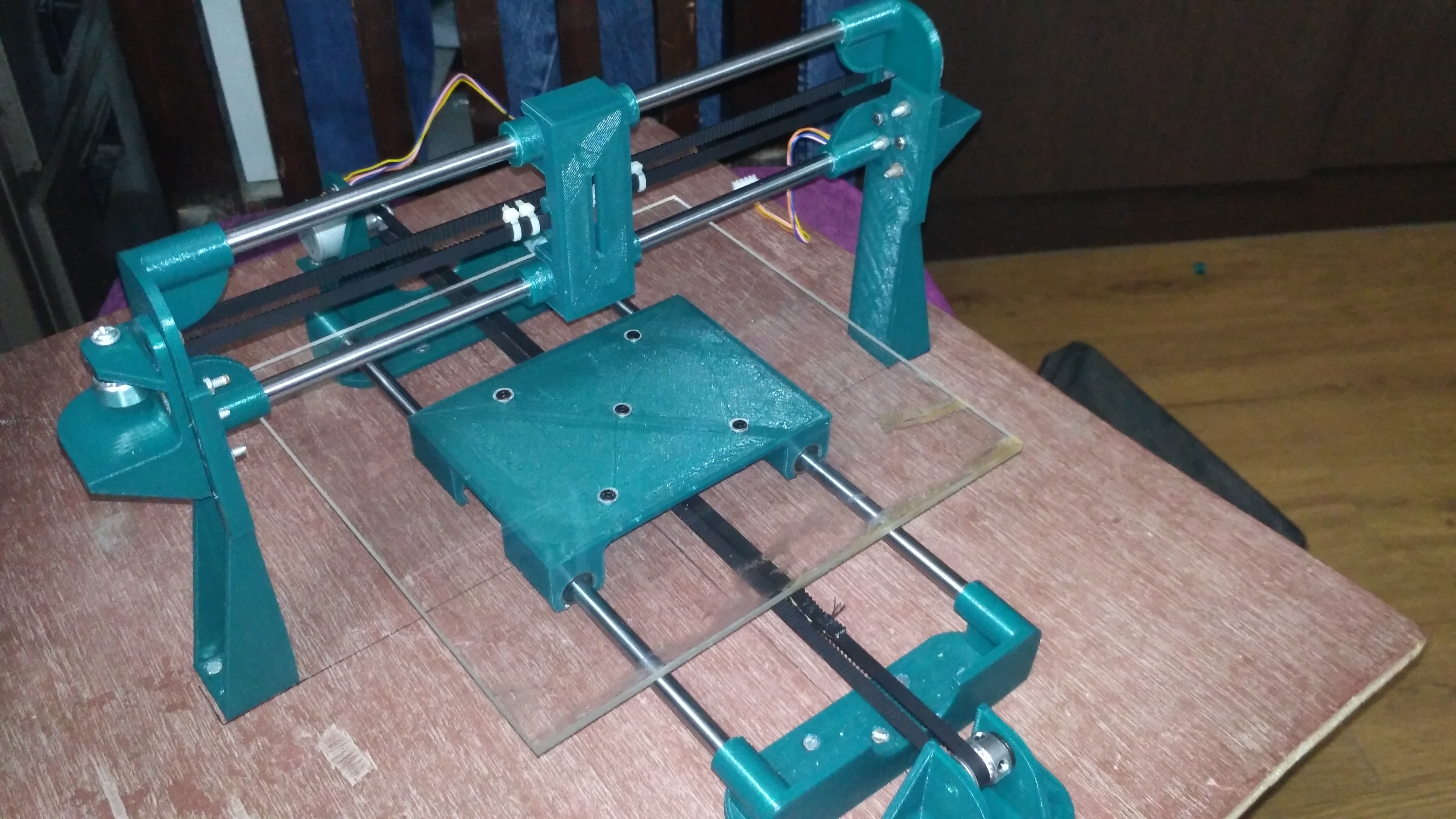
ASSEMBLING THE Y AXIS
.png)
.png)
.png)
.png)
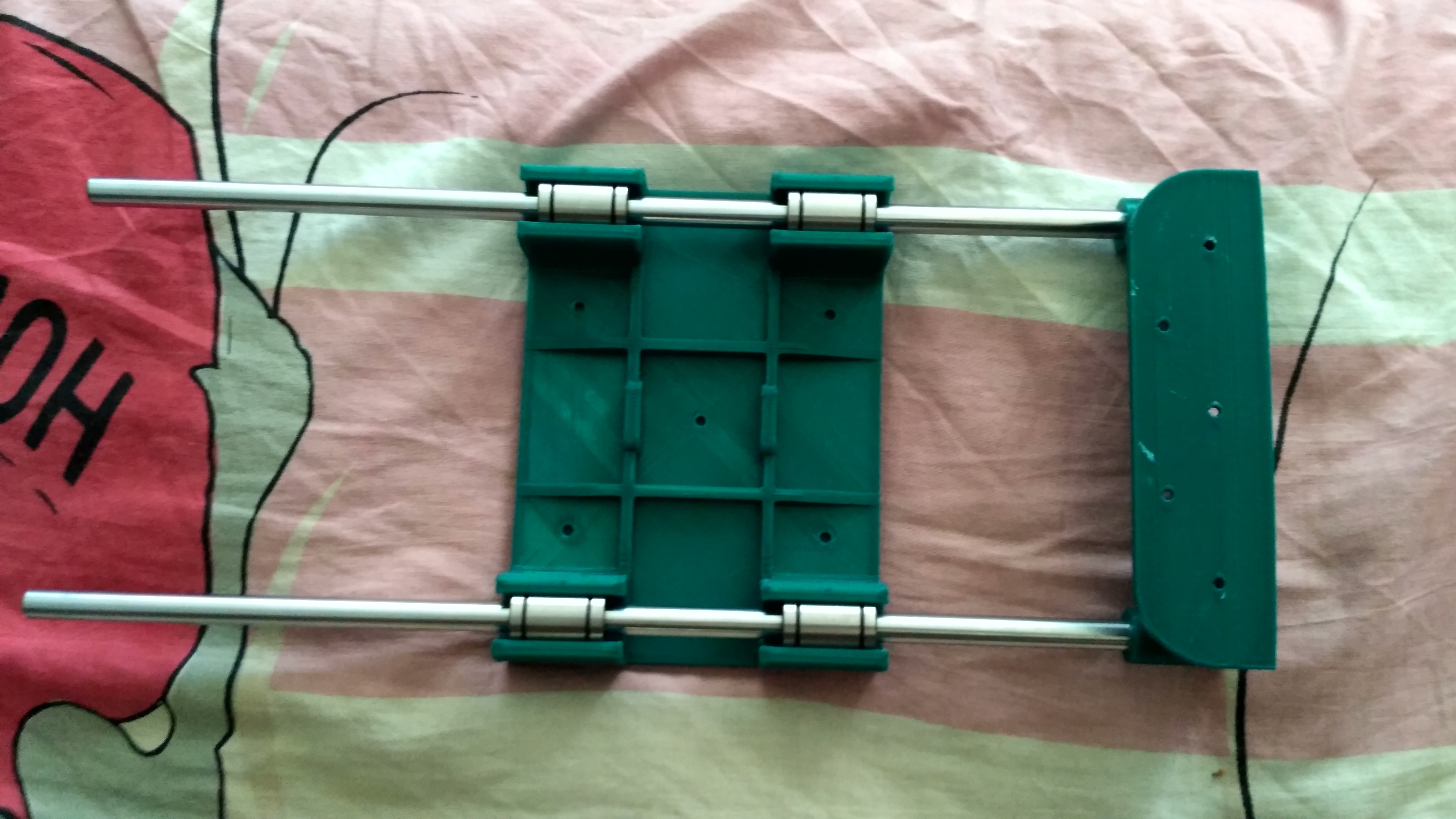
The first thing I would recommend you guys to do before starting the assembly is to keep the Fusion 360 assembly file open in your PC. This helps in making the assembly process less confusing.
Fusion 360 lets us hide all the unwanted components for the time being so that we can concentrate better on the area we are assembling.
Here I have attached screenshots from Fusion 360 as well as the actual assembly pictures.
Steps of assembly:
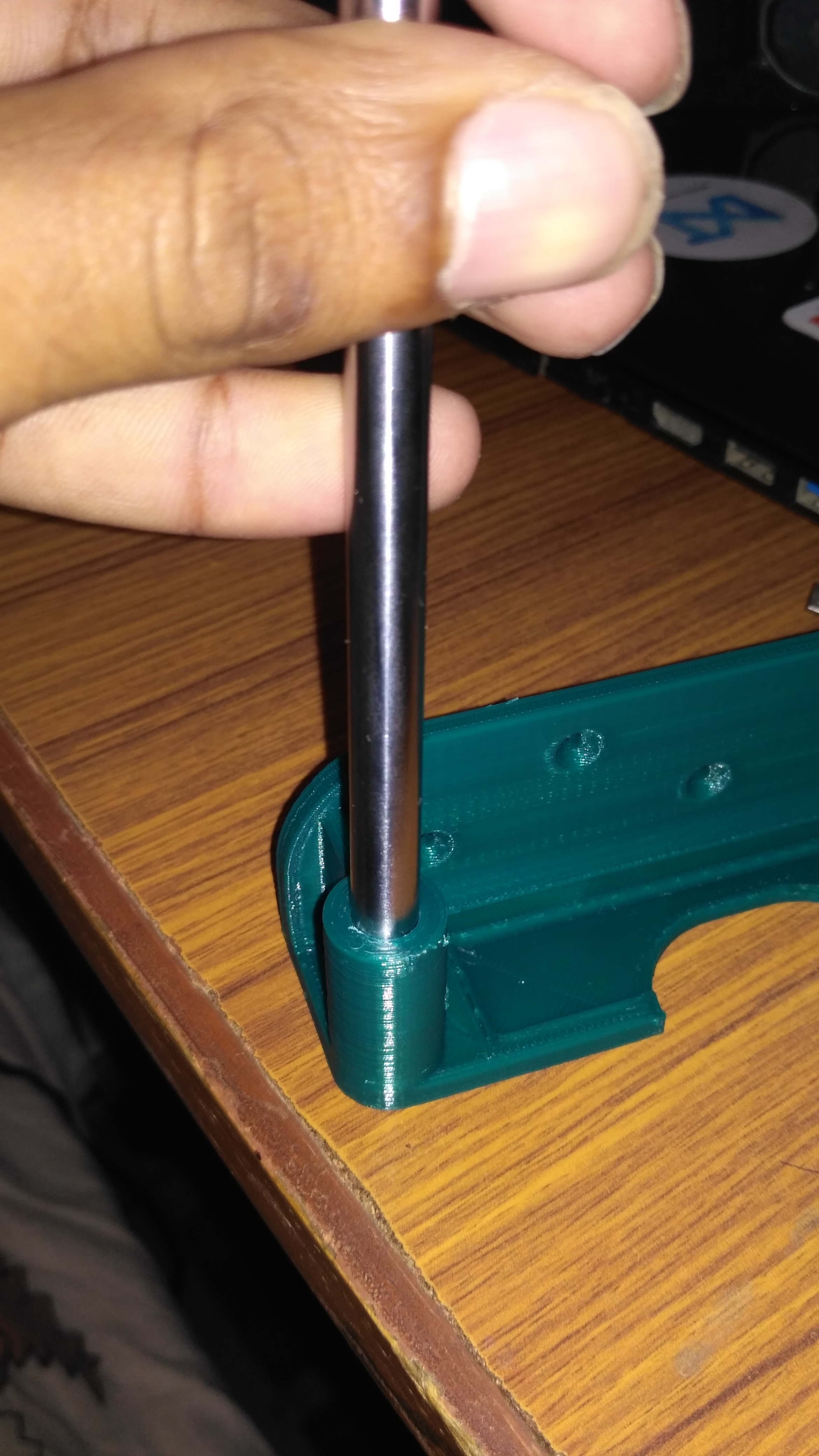
- Two of the smooth rods are inserted into one of the Y-axis smooth rod holders. I have designed the bores such that the rods will have a tight fit in order to avoid glue. Gently tap the rods with a hammer if necessary.
- Four linear bearings are inserted into the slots provided for it beneath the Y-axis carriage. Here again, it's a tight fit, so the glue won't be necessary.
- Now slide the open end of the smooth rods in through the linear bearings.
- Insert the other smooth rod holder at the open ends of the smooth rods.
Make sure that the carriage can easily slide from one end to the other in a smooth manner.
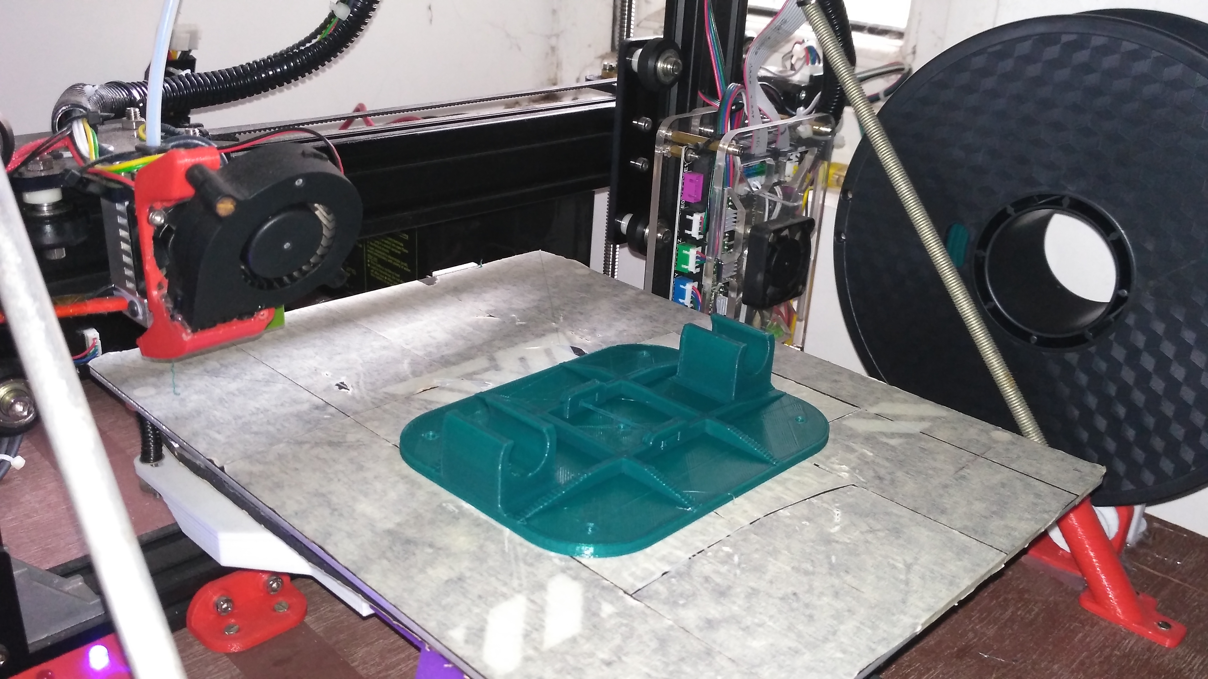
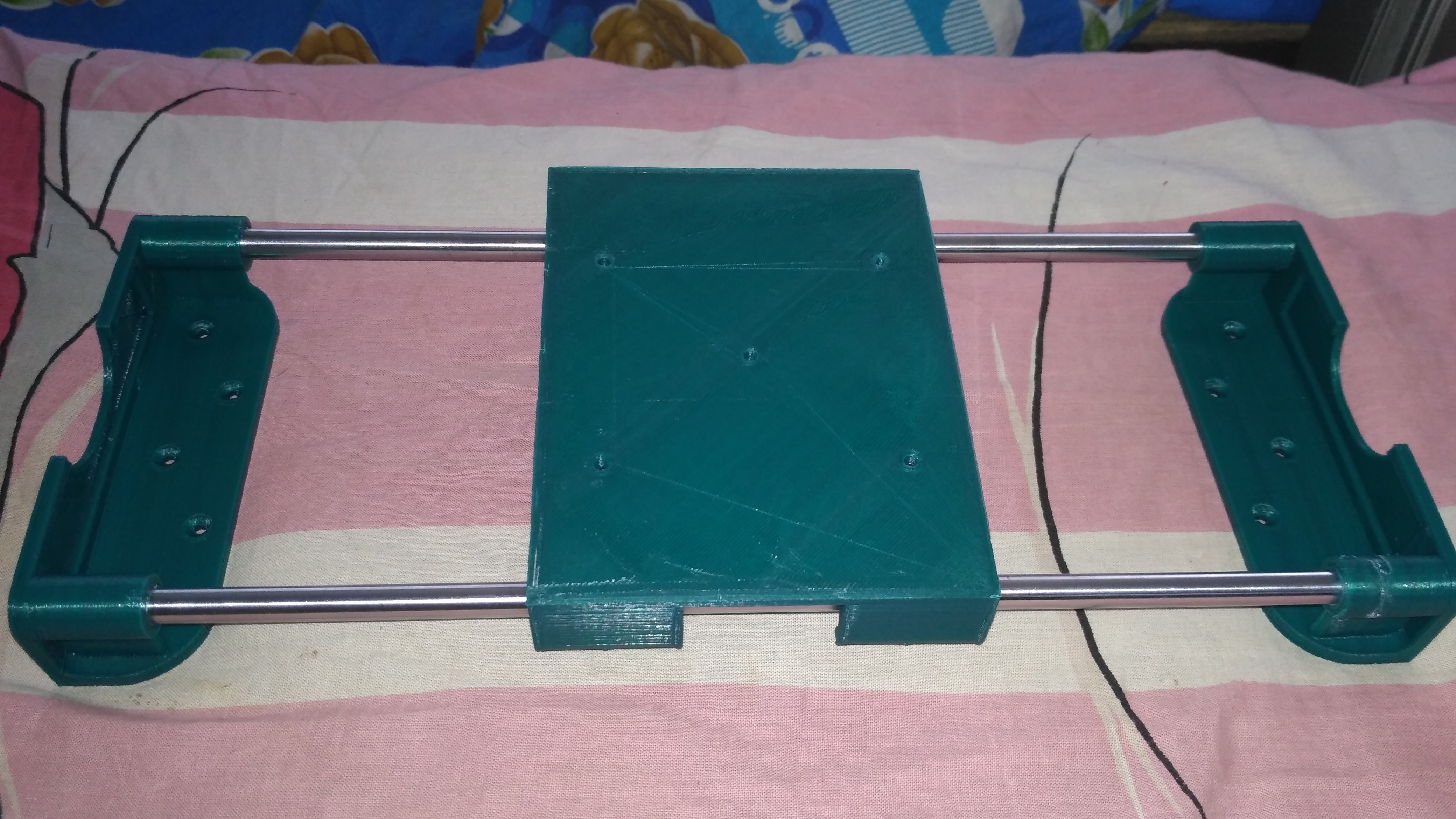
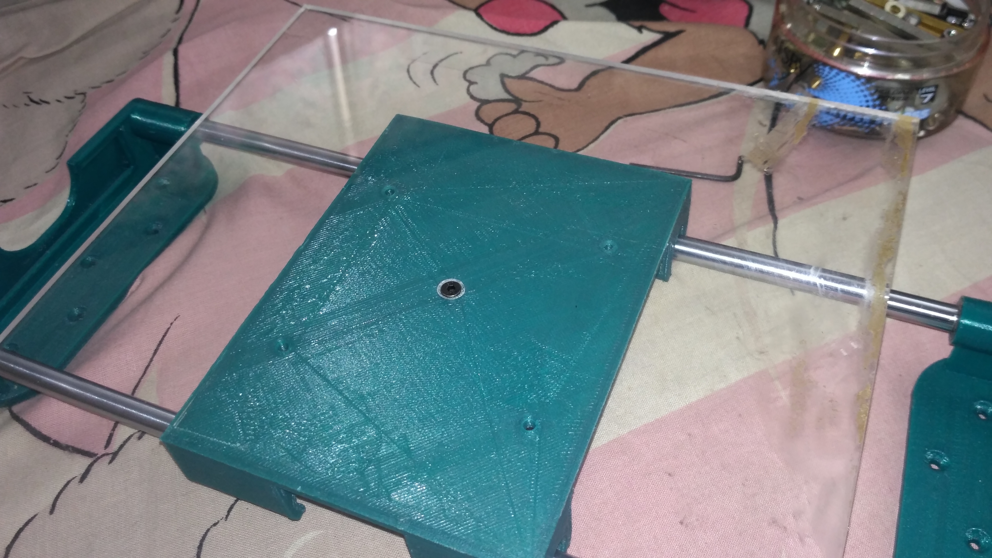
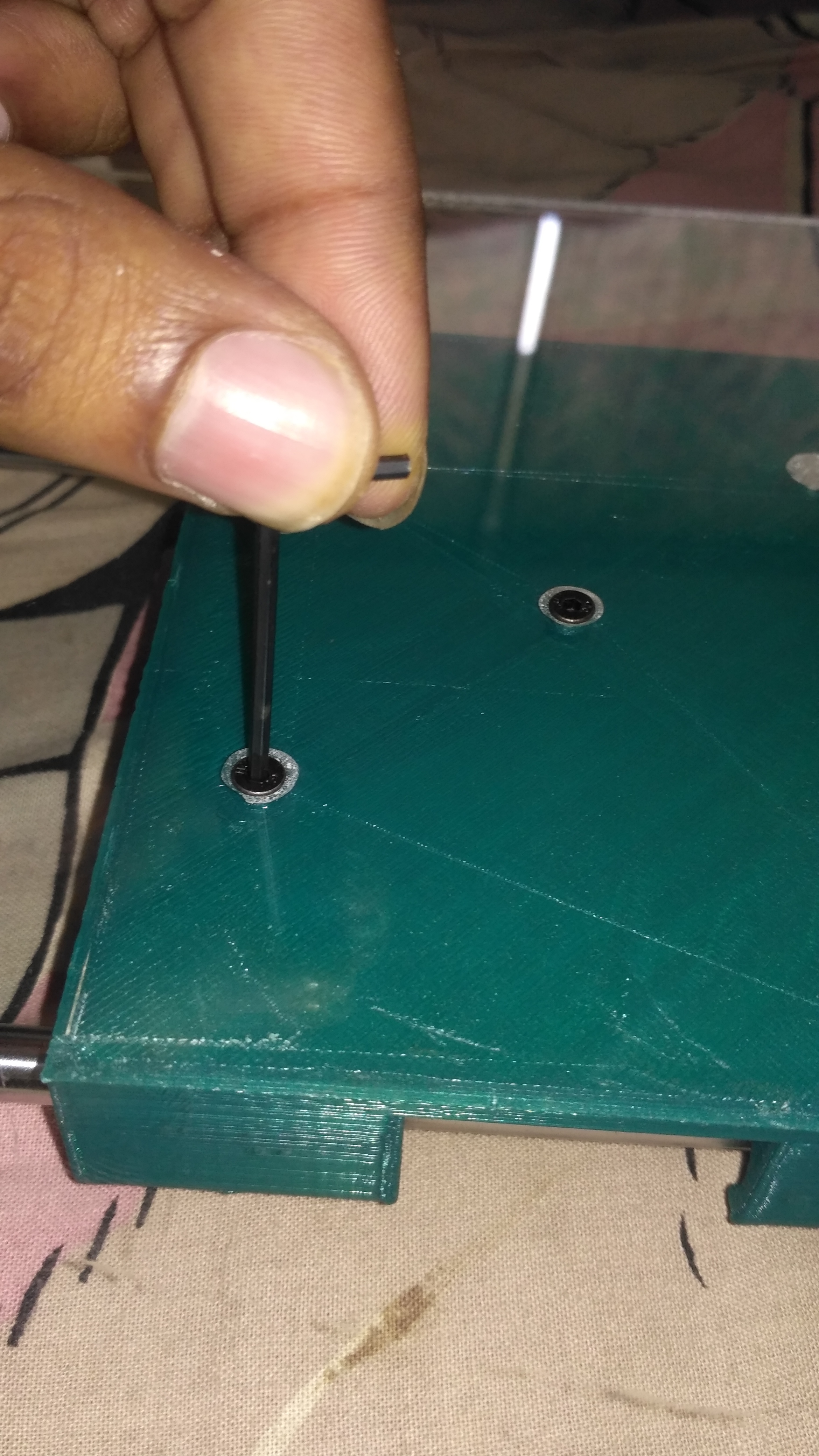
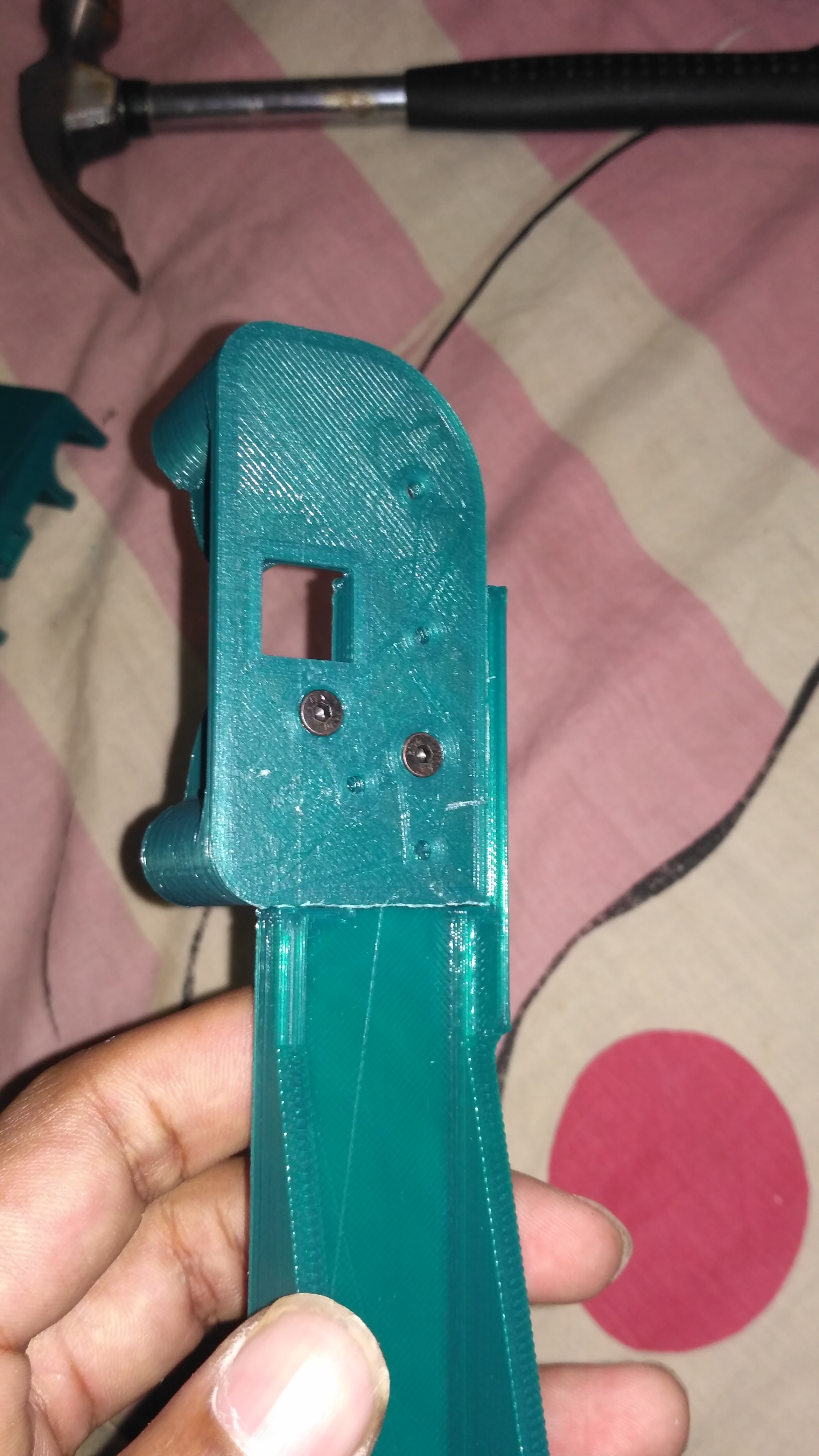
ATTACHING THE BUILT PLATE:
.png)
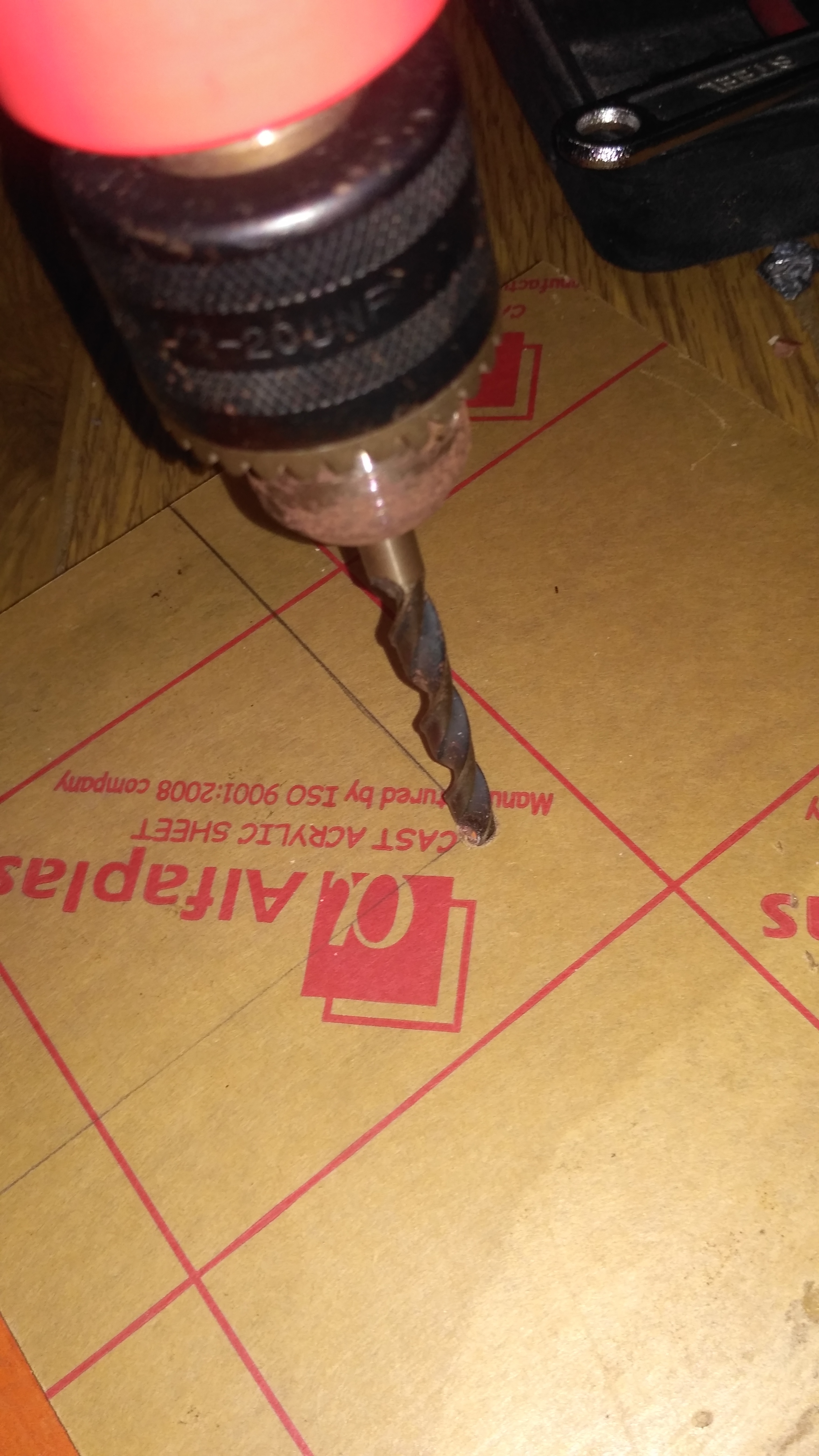
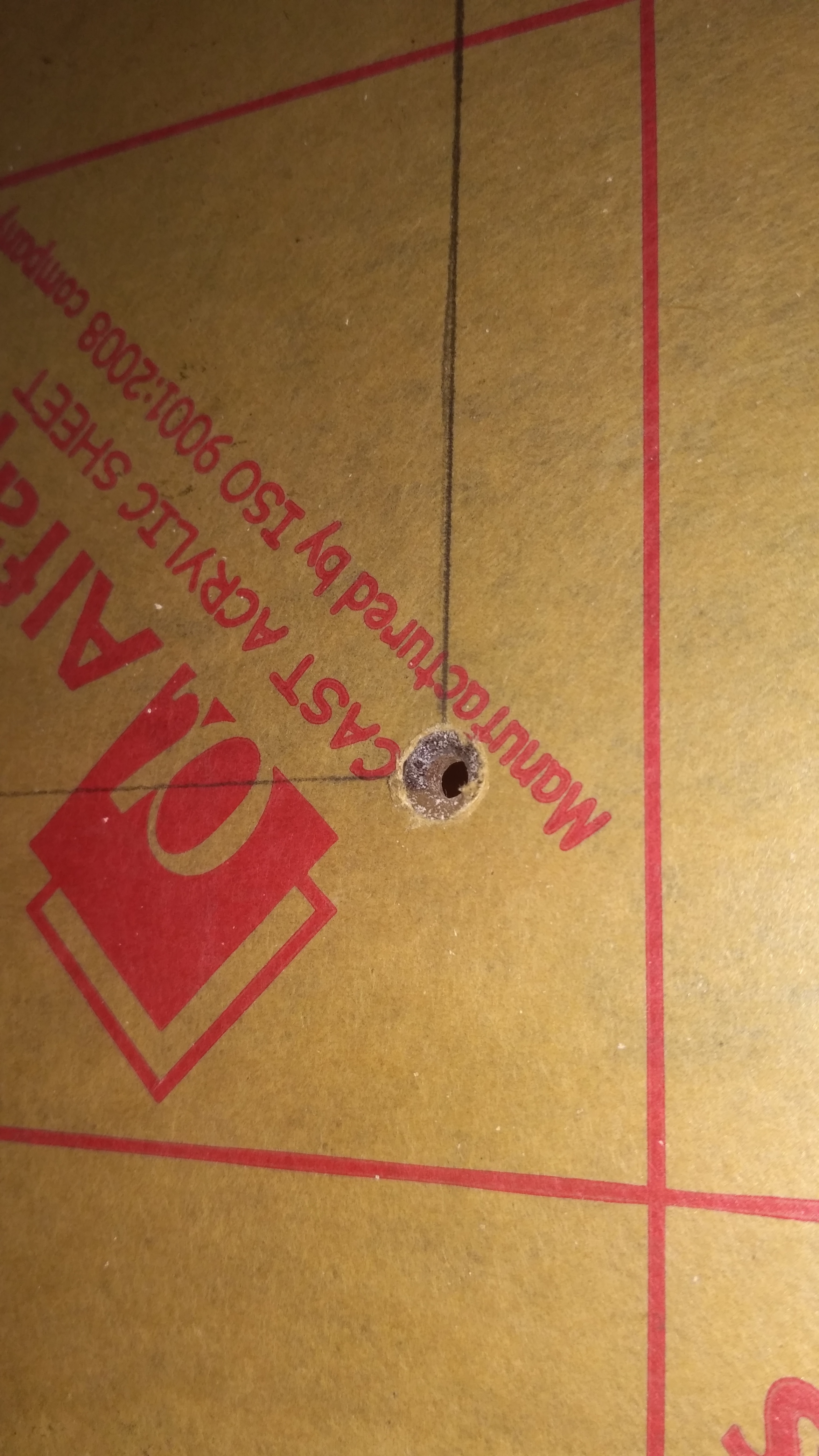
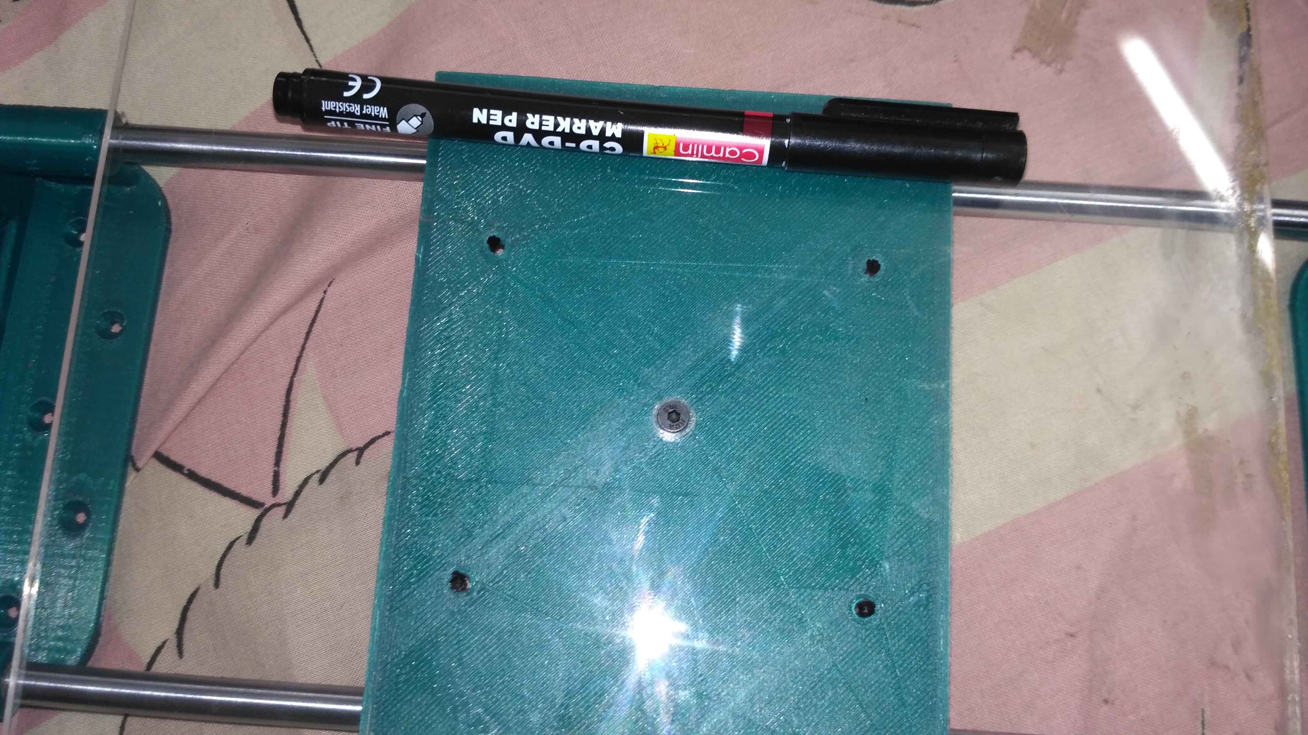
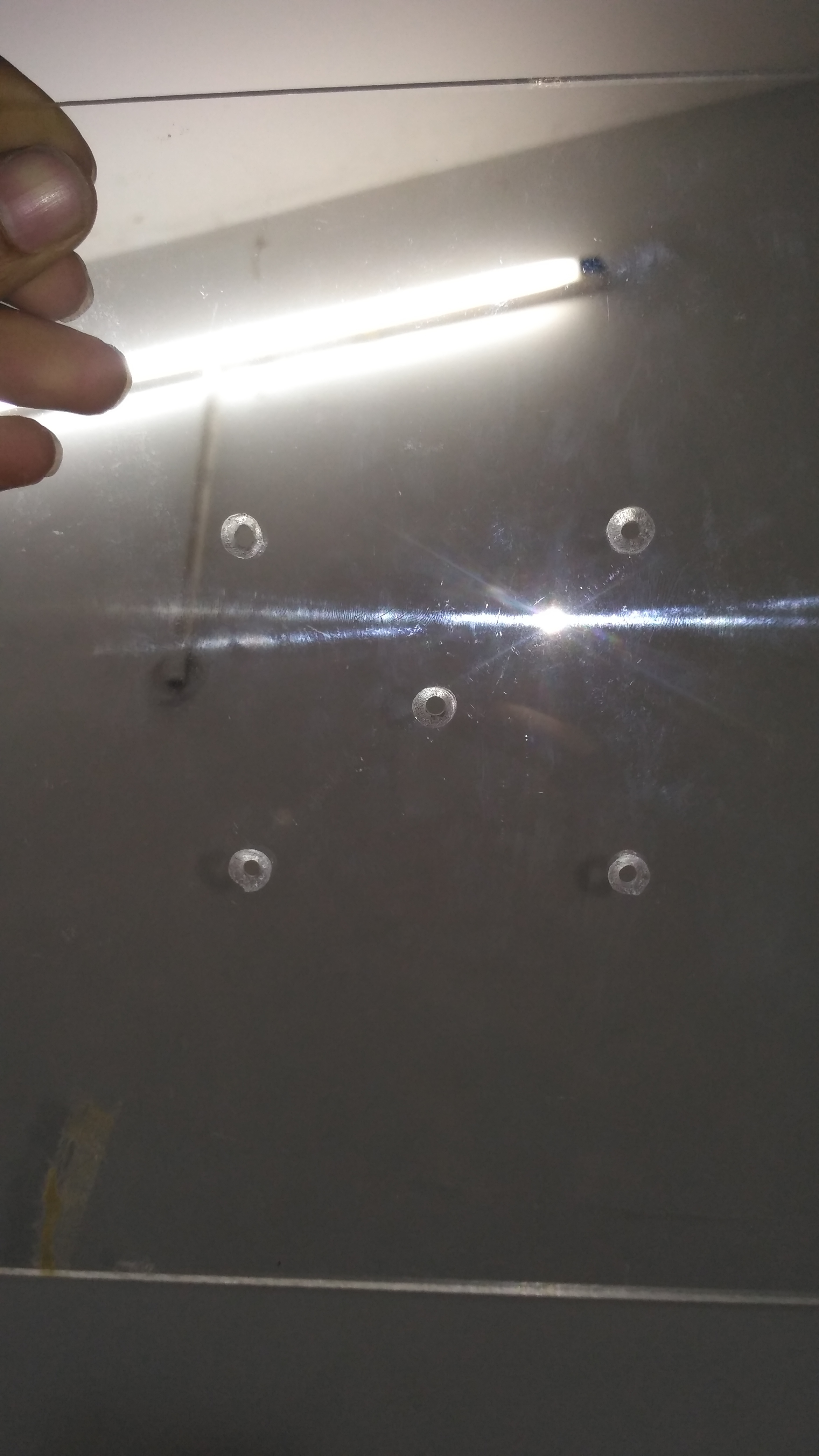
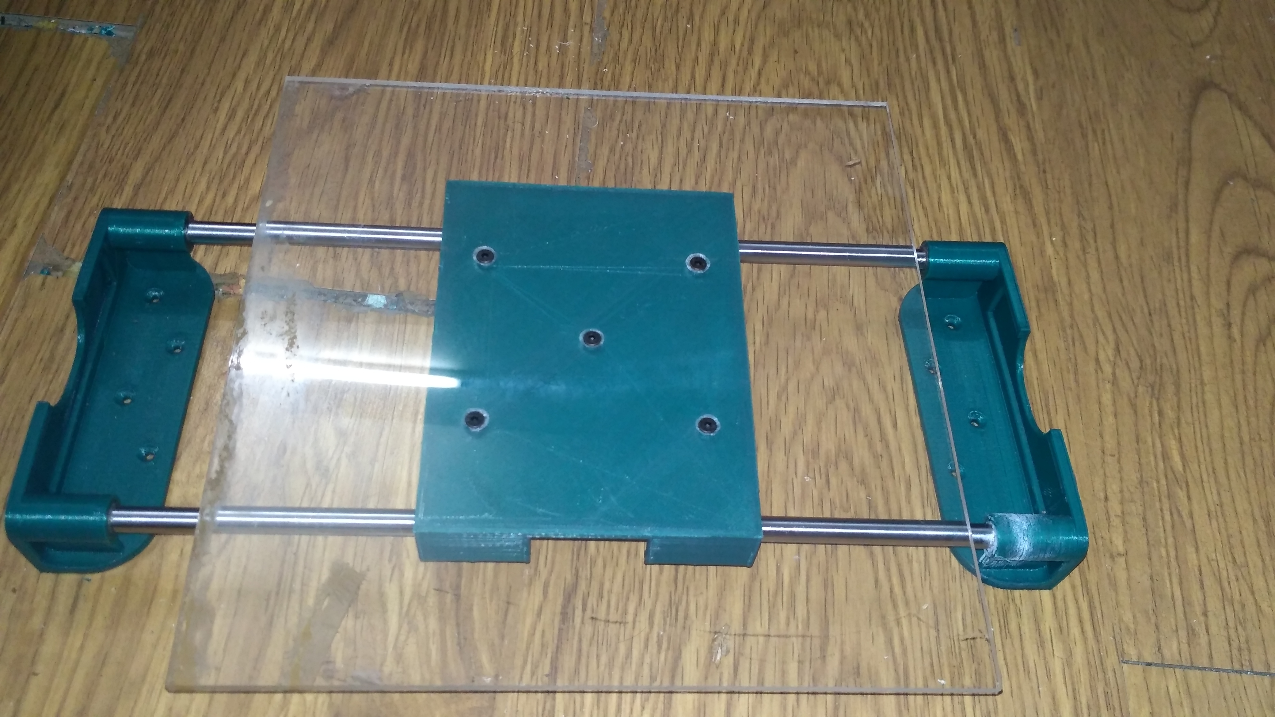
- Drill a hole in the middle of the 22 X 22 cm transparent acrylic sheet.
- Bolt the sheet on the Y-axis carriage using a single nut and bolt in the middle.
- Adjust the sheet until the edges of the sheet are parallel to the edges of the carriage.
- Mark the remaining four hole positions on the acrylic sheet with a marker for drilling reference.
- Remove the sheet from the carriage and drill all the holes with a 3mm drill bit.
- Using a suitable bigger bit and countersink the 3mm holes so that the bolt head won't stick out.
- Finally, attach the build plate (acrylic sheet) to the Y-axis carriage using M3 12mm bolts and nuts.
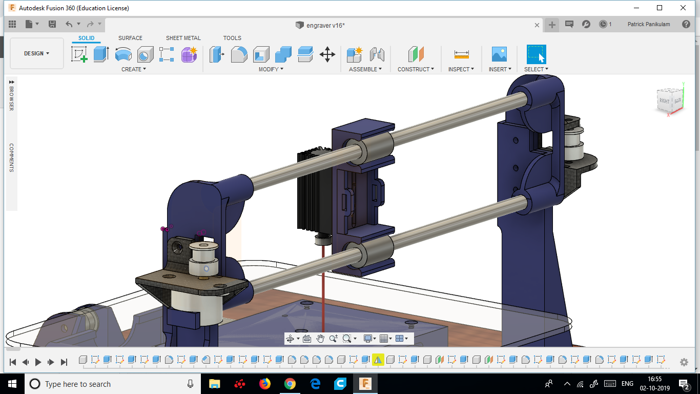
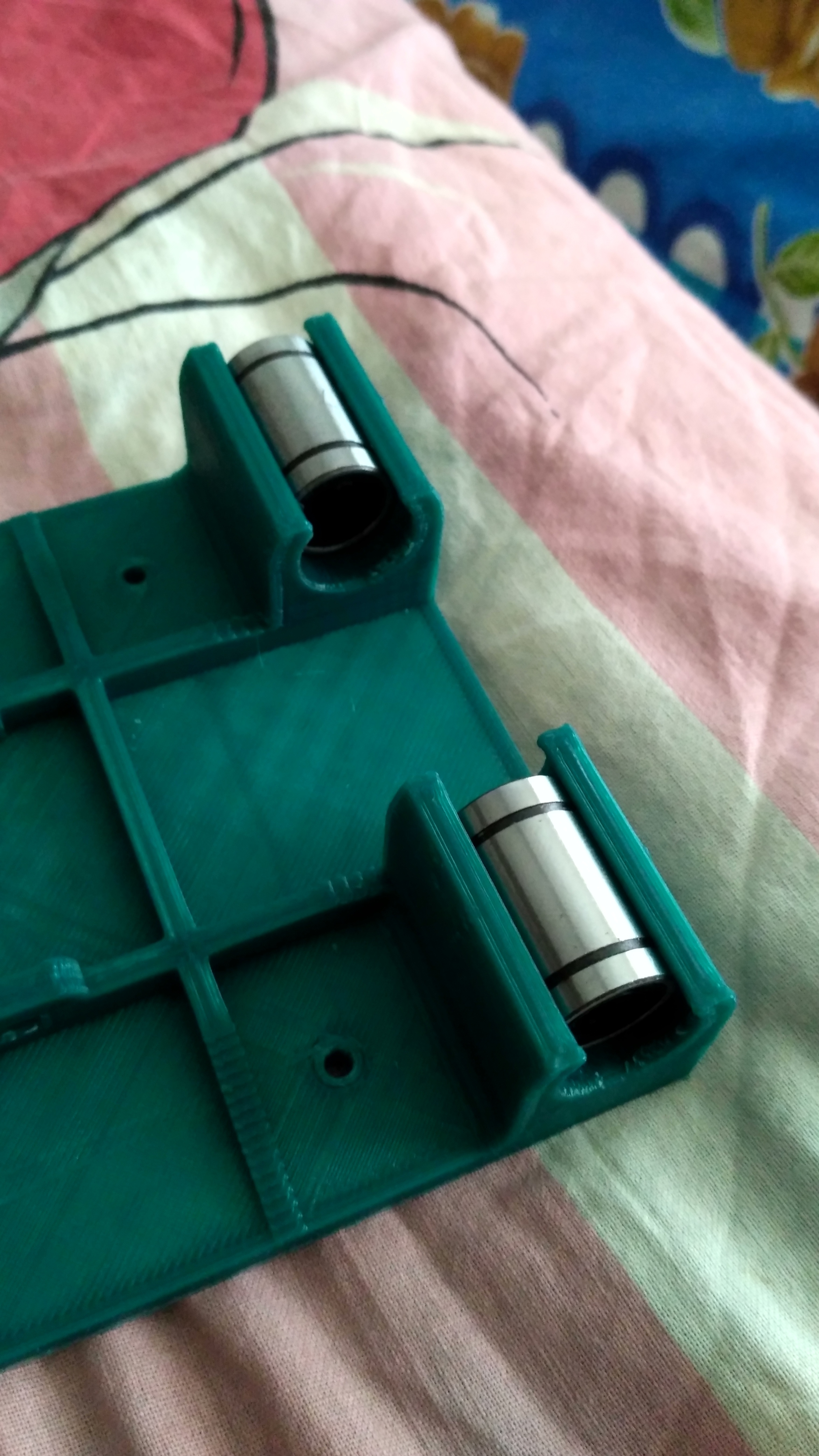
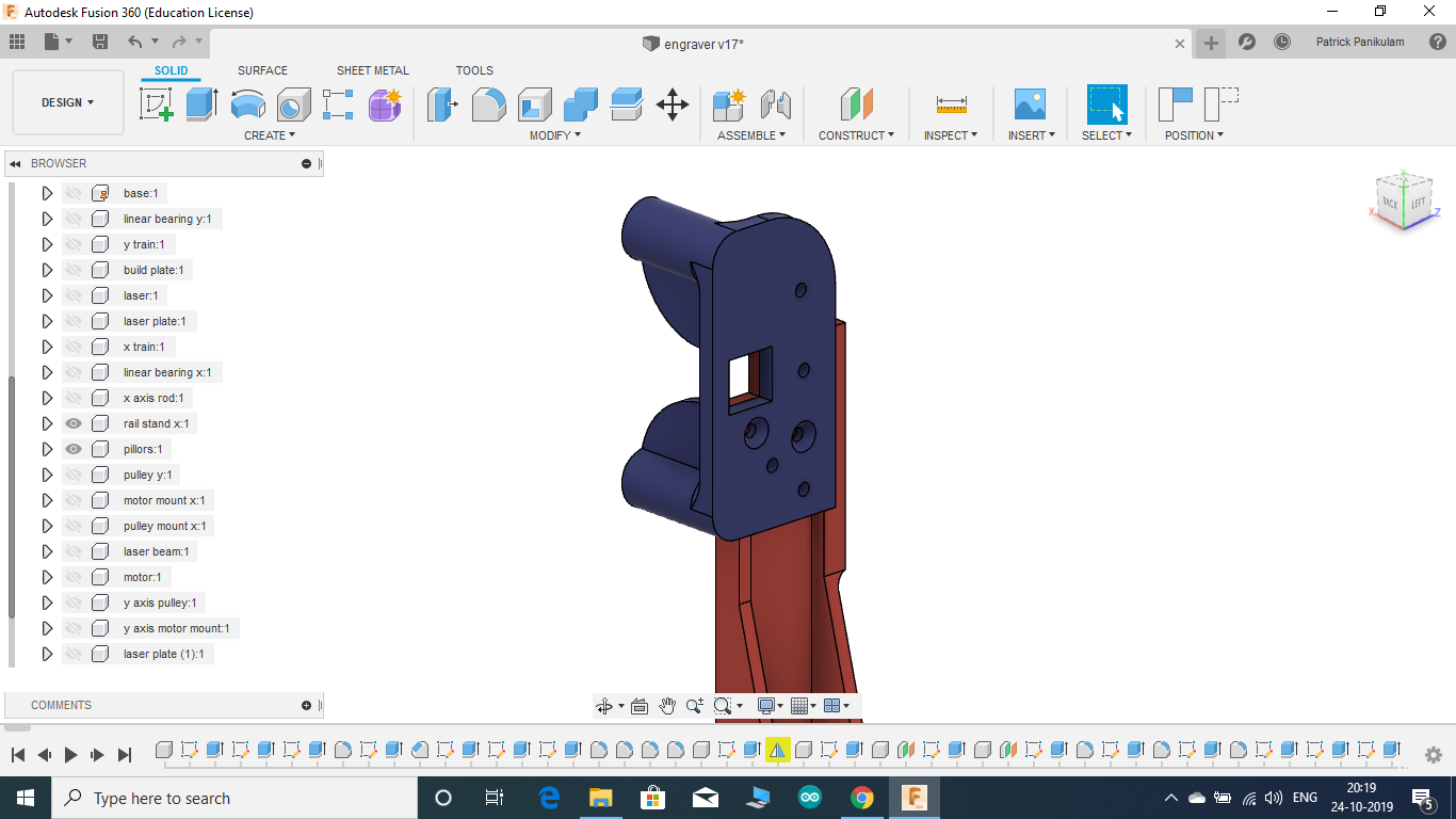
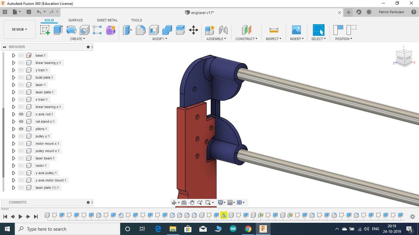
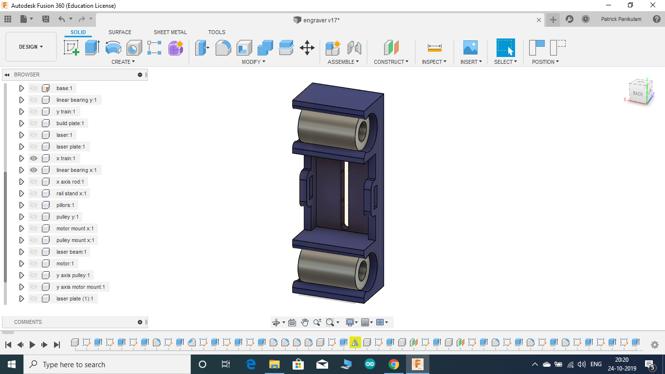
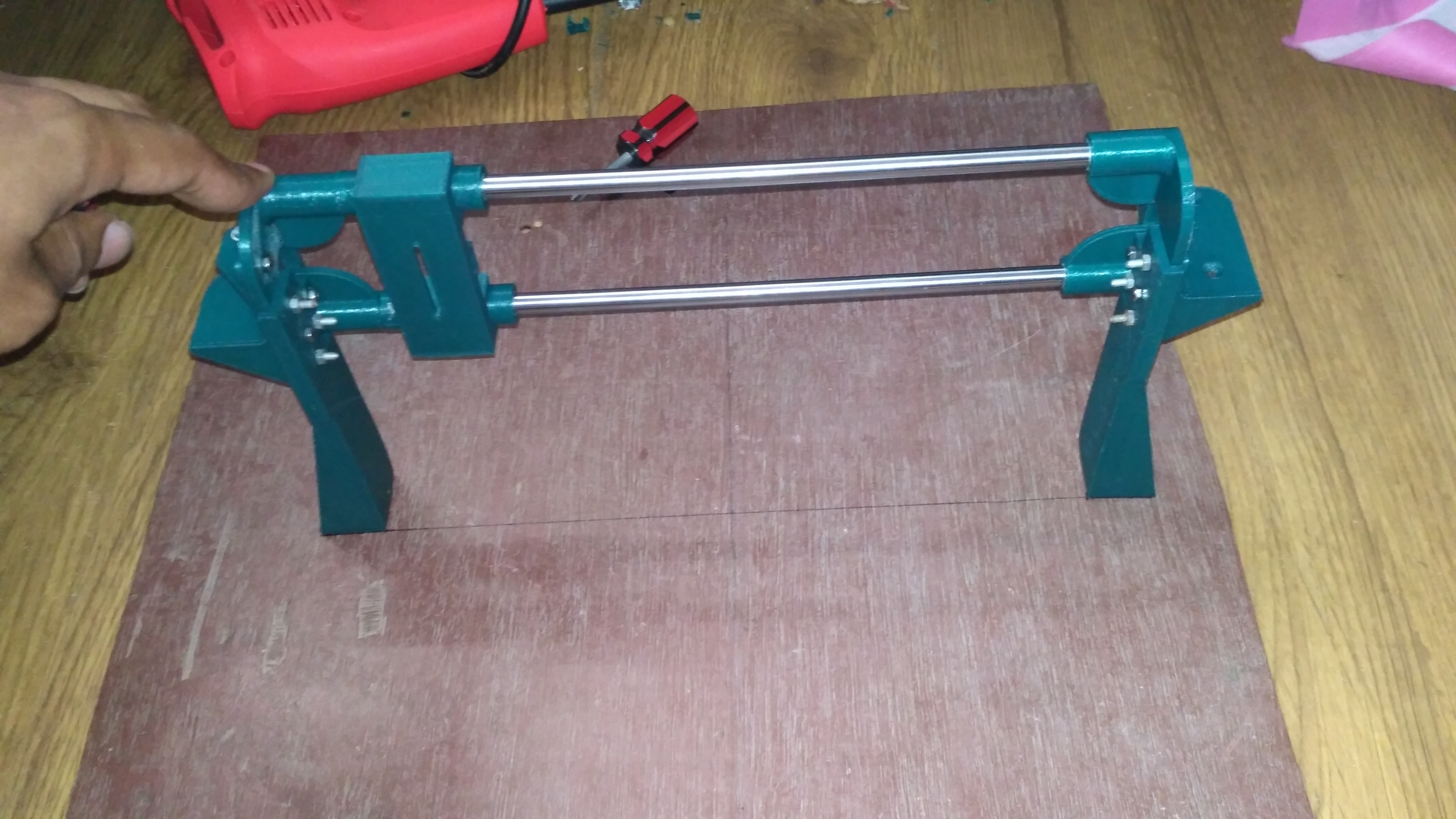
ASSEMBLING THE X-AXIS
.png)
.png)
.png)
.png)
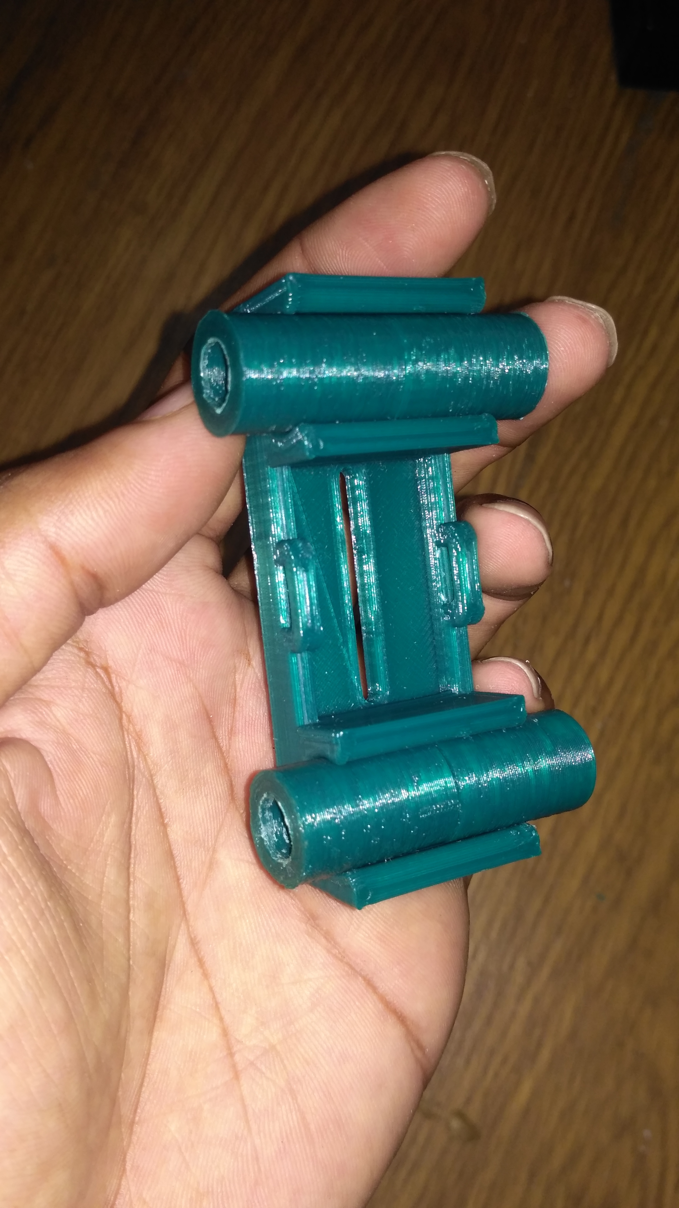
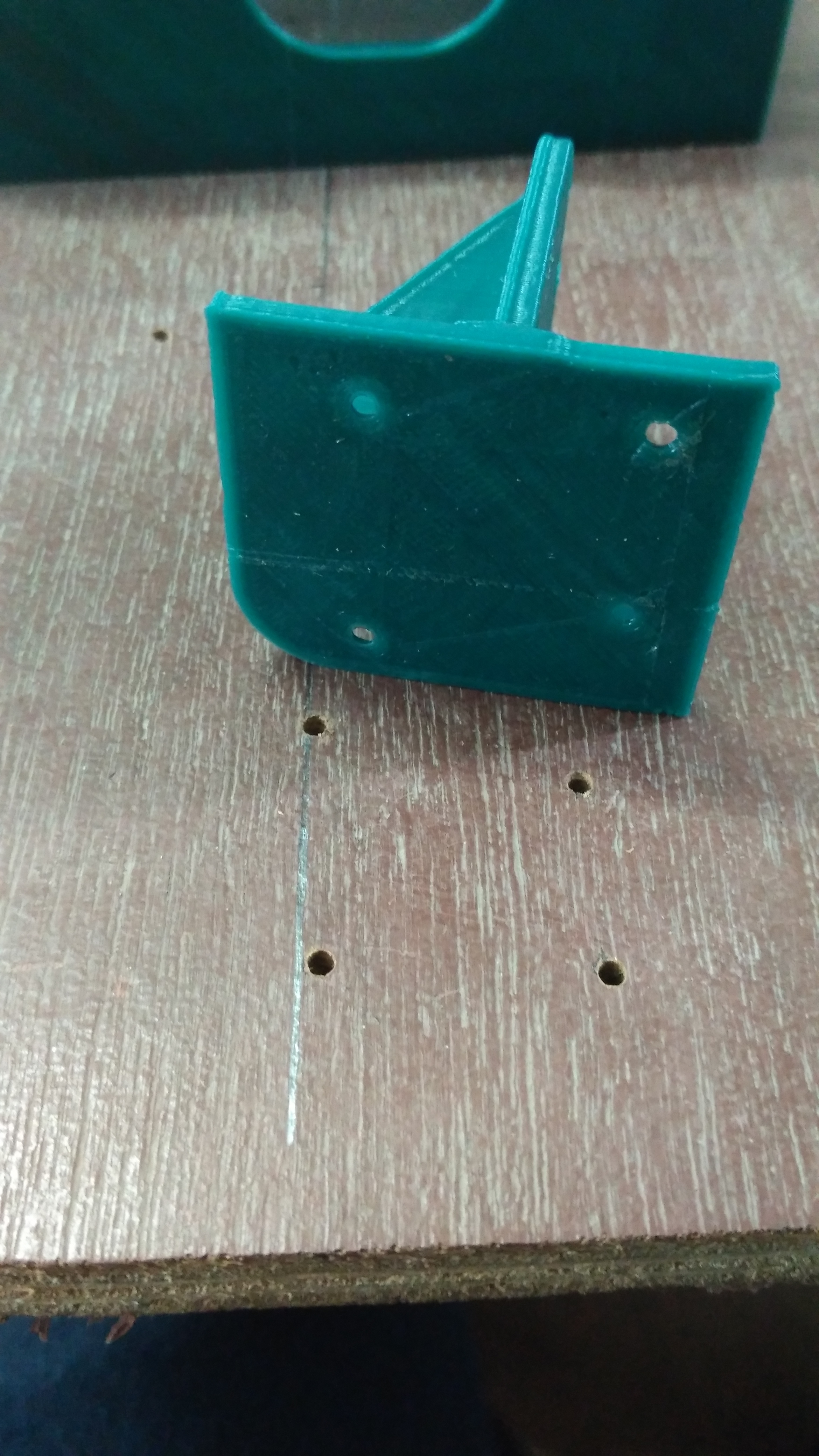
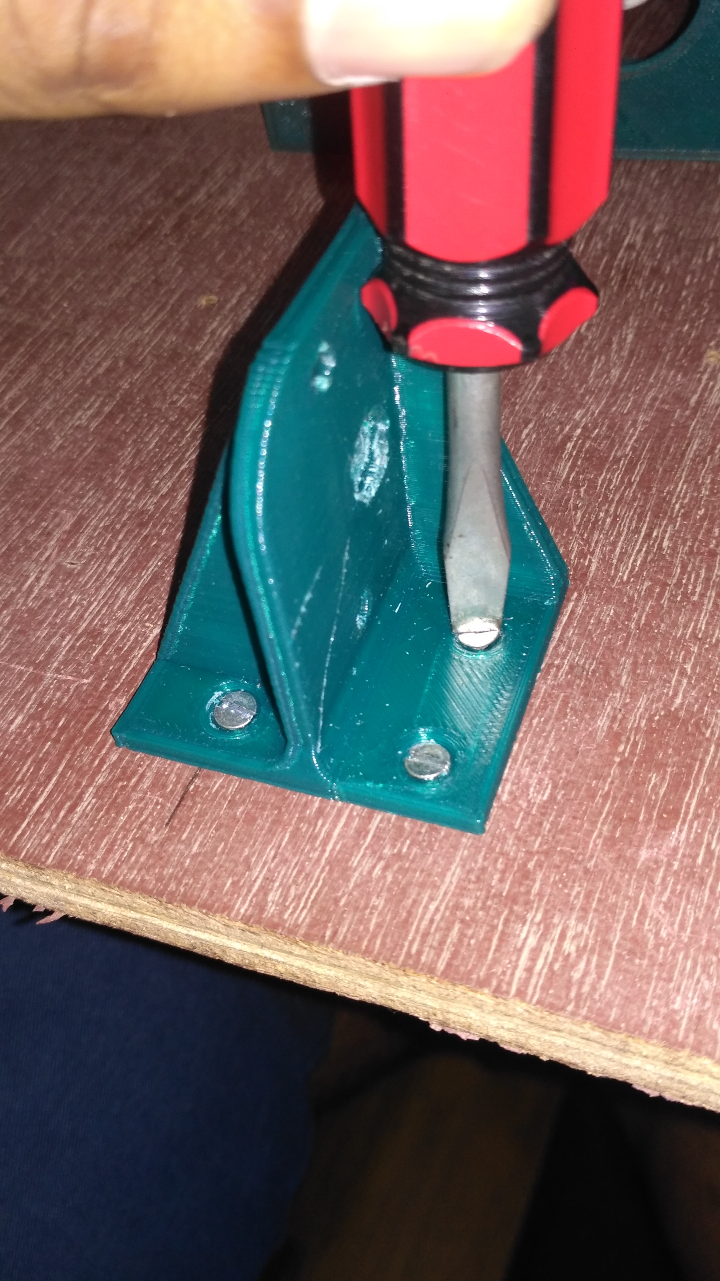
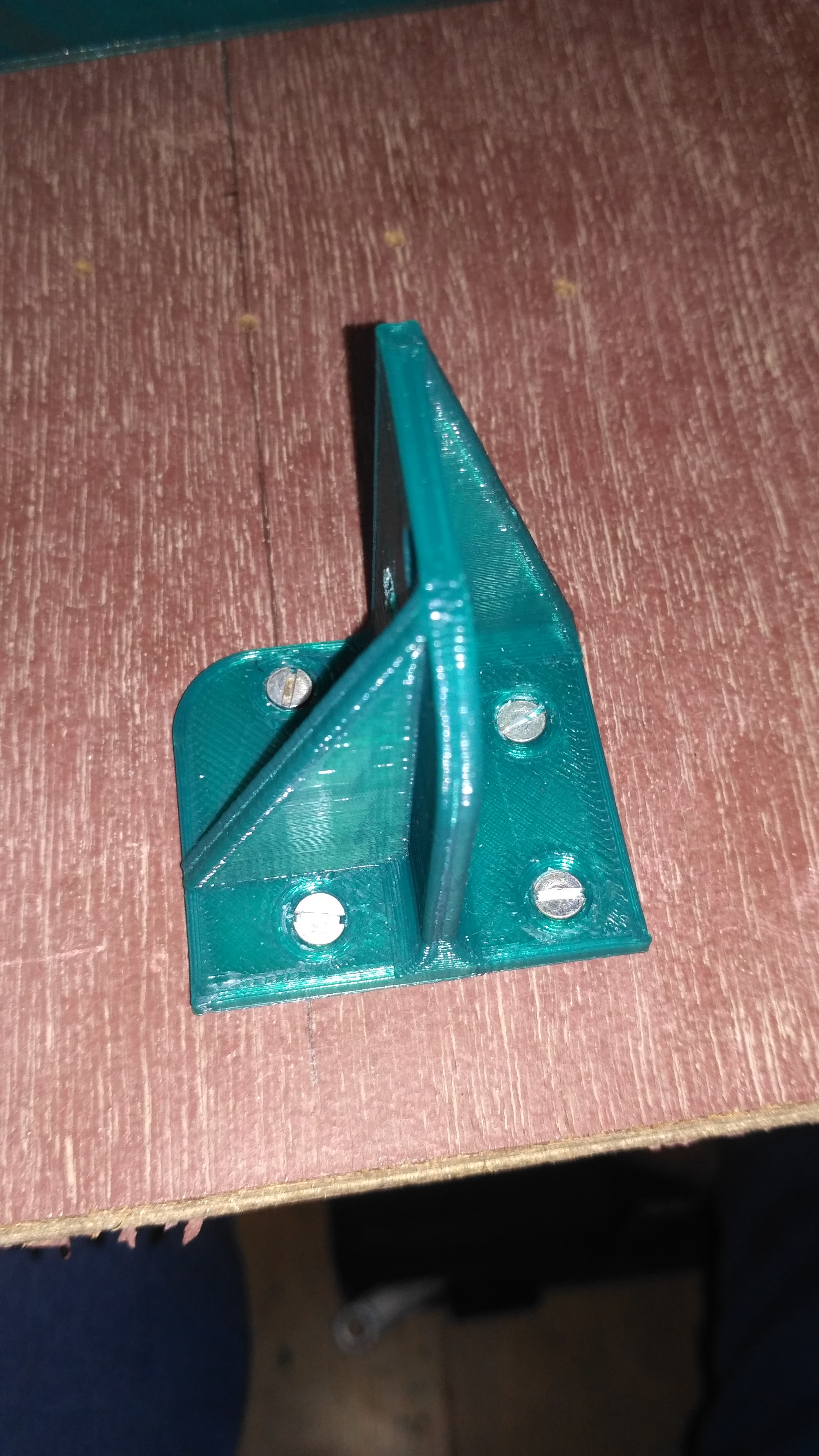
- First, fasten the X-axis rod holders and the pillars together using two M3 12mm bolt and nut as shown in the picture.
- Now insert both the smooth rods into one of the rod holders just like we did for the Y-axis.
- Tight fit the linear bearings onto the X-axis carriage.
- Slide-in the carriage through the open ends of the smooth rods and then insert the second holder at the open ends.
You guys might have noticed that I used 3D printed bearings instead of metals ones. This was because two of the bearings I received were damaged and caused the wobbling of the carriage. The bores of the 3D printed bearings are smoothened using fine sandpaper and oil is applied for smooth motion. They worked just as well as the metal ones.
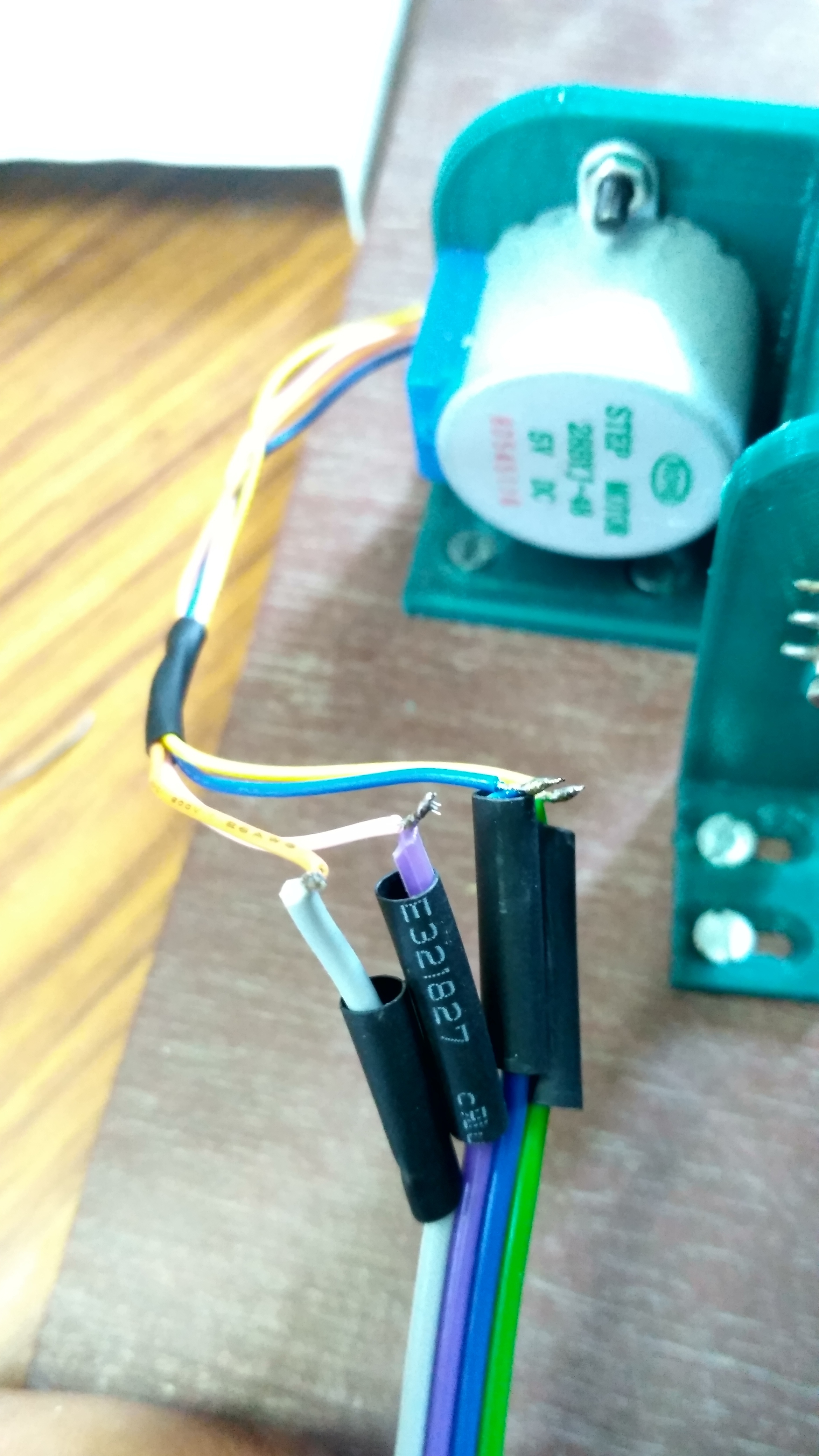
Converting the Unipolar 28BYJ-48 Motor Into a Bipolar Motor
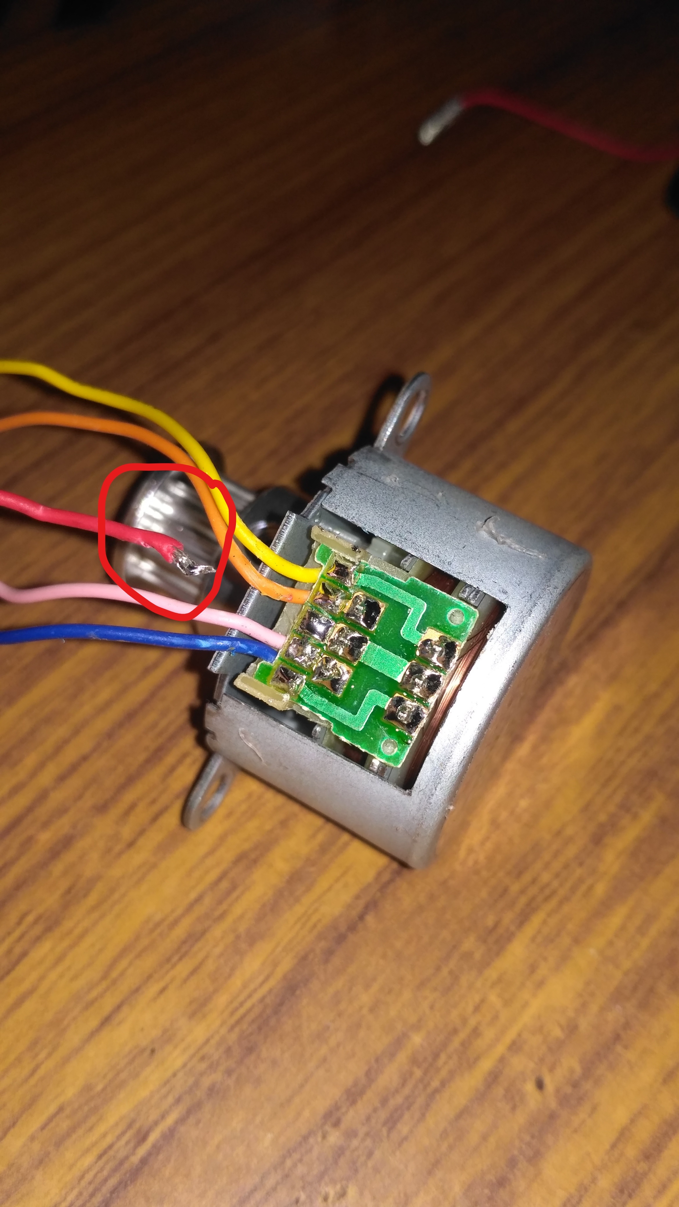
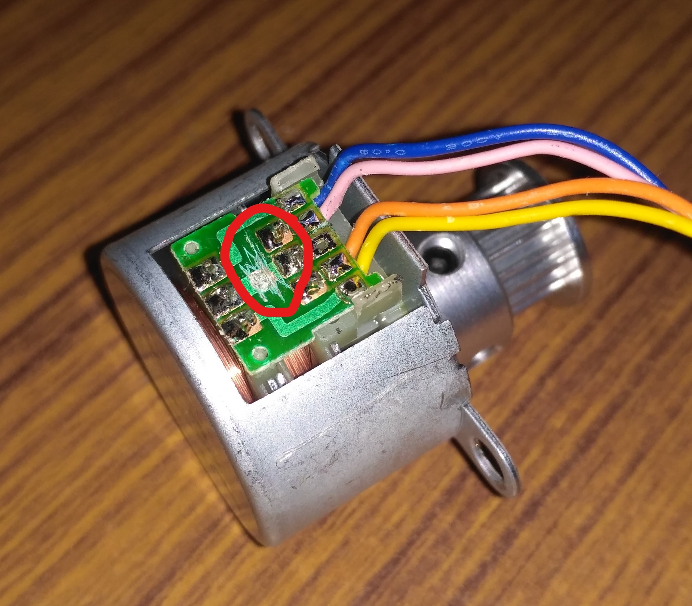
There are 2 main reasons why we are converting the unipolar motor into a bipolar motor.
- Algorithm for controlling a bipolar motor via an A4988 stepper motor driver is simpler than controlling a unipolar motor
- The CNC shield only supports A4988 stepper motor drivers, thus the shield only supports bipolar stepper motors and hence conversion is a must.
The conversion can be done in 3 simple steps:-
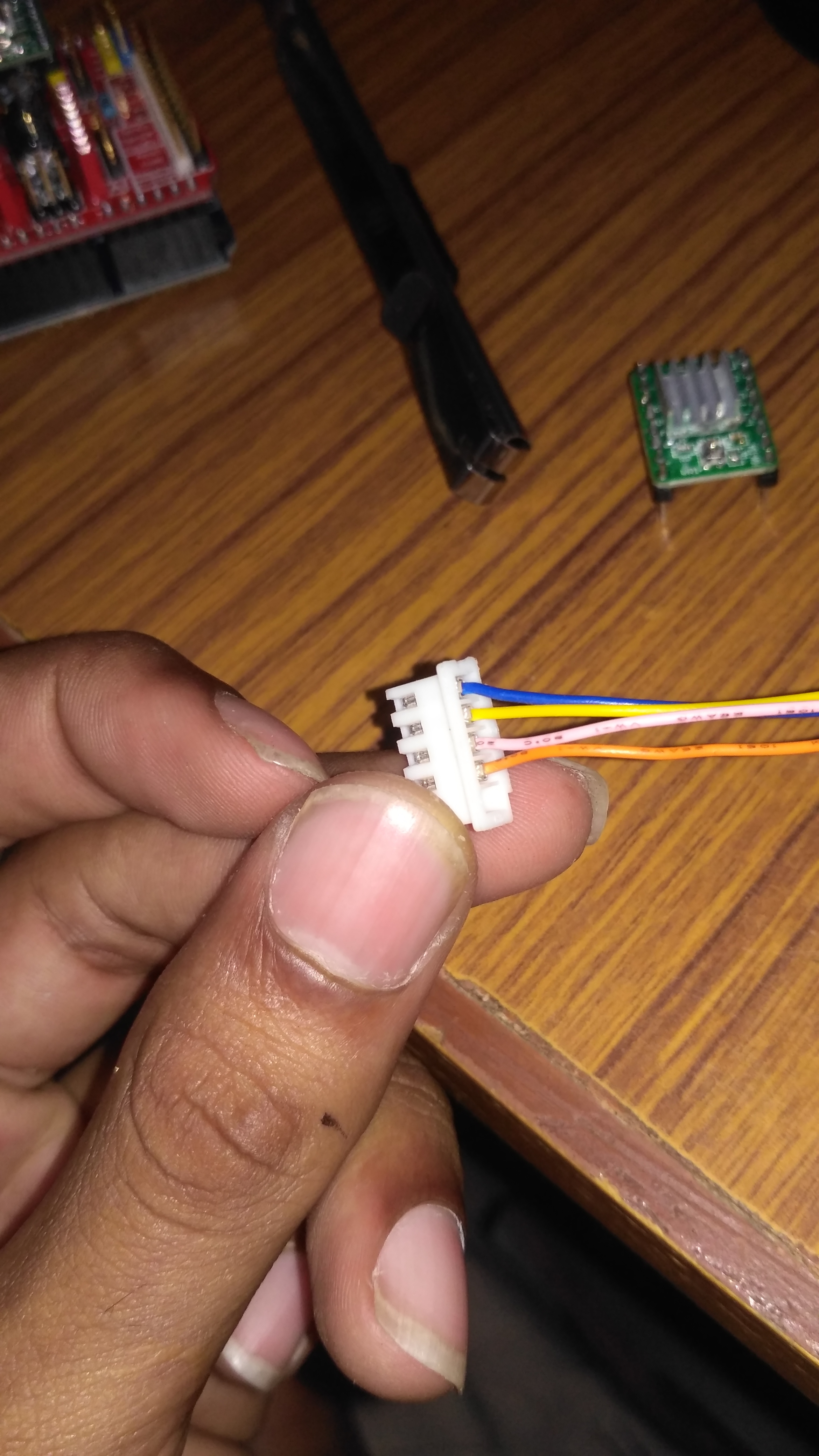
- After opening the blue plastic casing, desolder the red wire from the PCB as seen in the first picture.
- Now using a sharp blade, scrape away the common connection between the two coils of the stepper motor as seen in the encircled portion of the second picture.
- Now rearrange the wires on the connector based on color as seen in the 3rd picture.
Watch this video by Make'n'Modify by clicking here for a better understanding of the procedure.
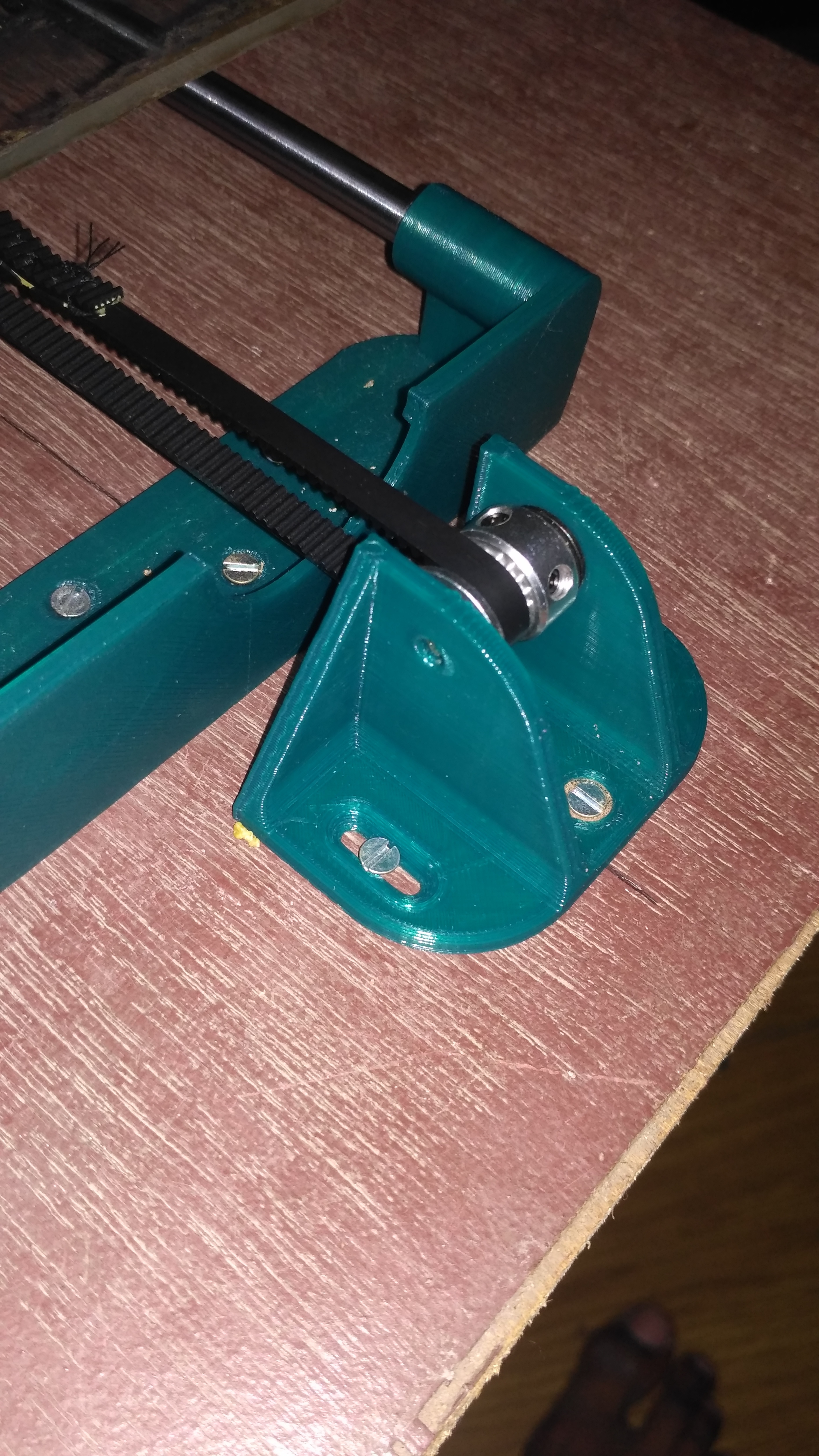
MOUNTING THE MOTOR , PULLEY AND THE BELT OF THE X-AXIS
.png)
.png)
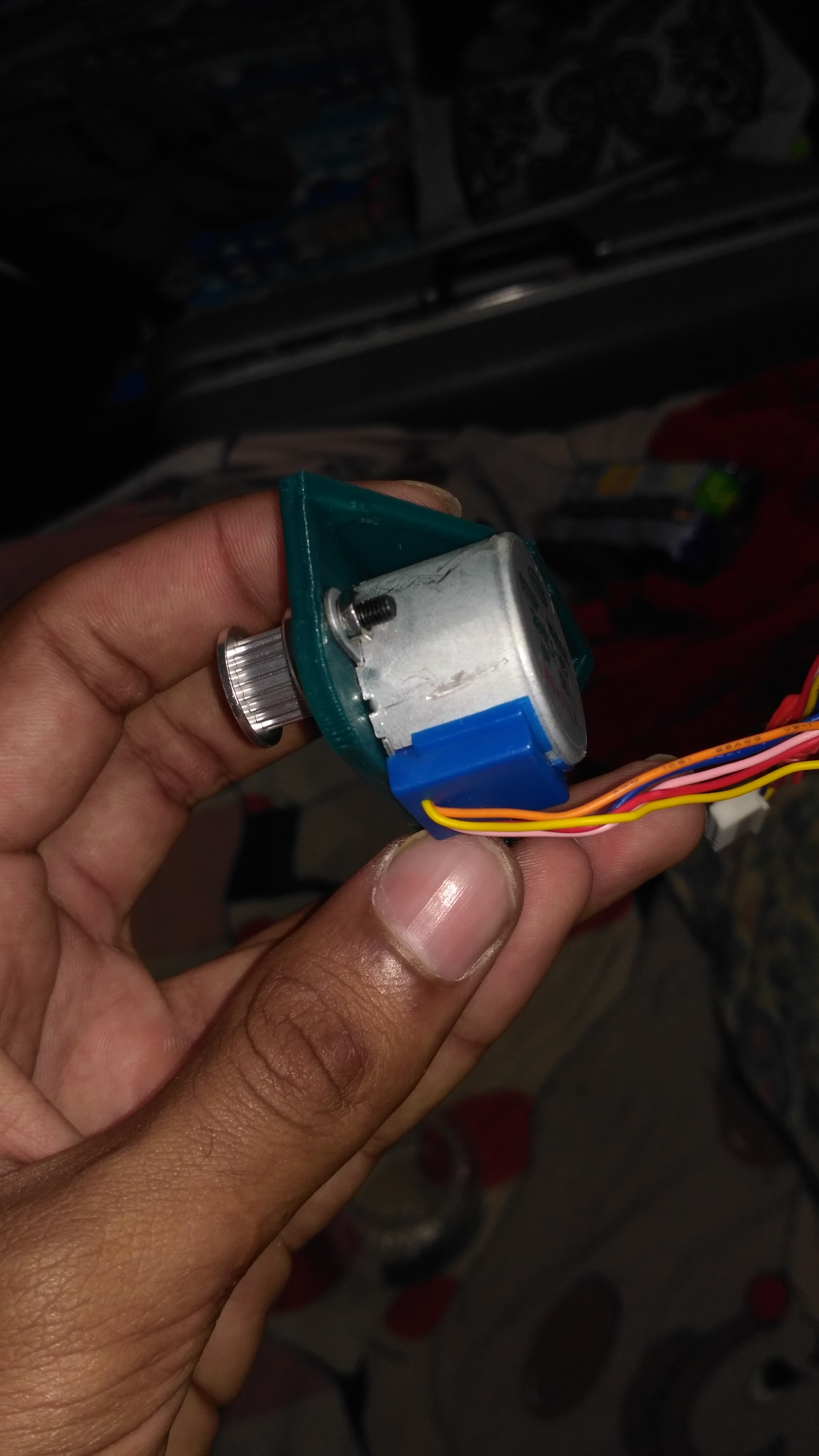
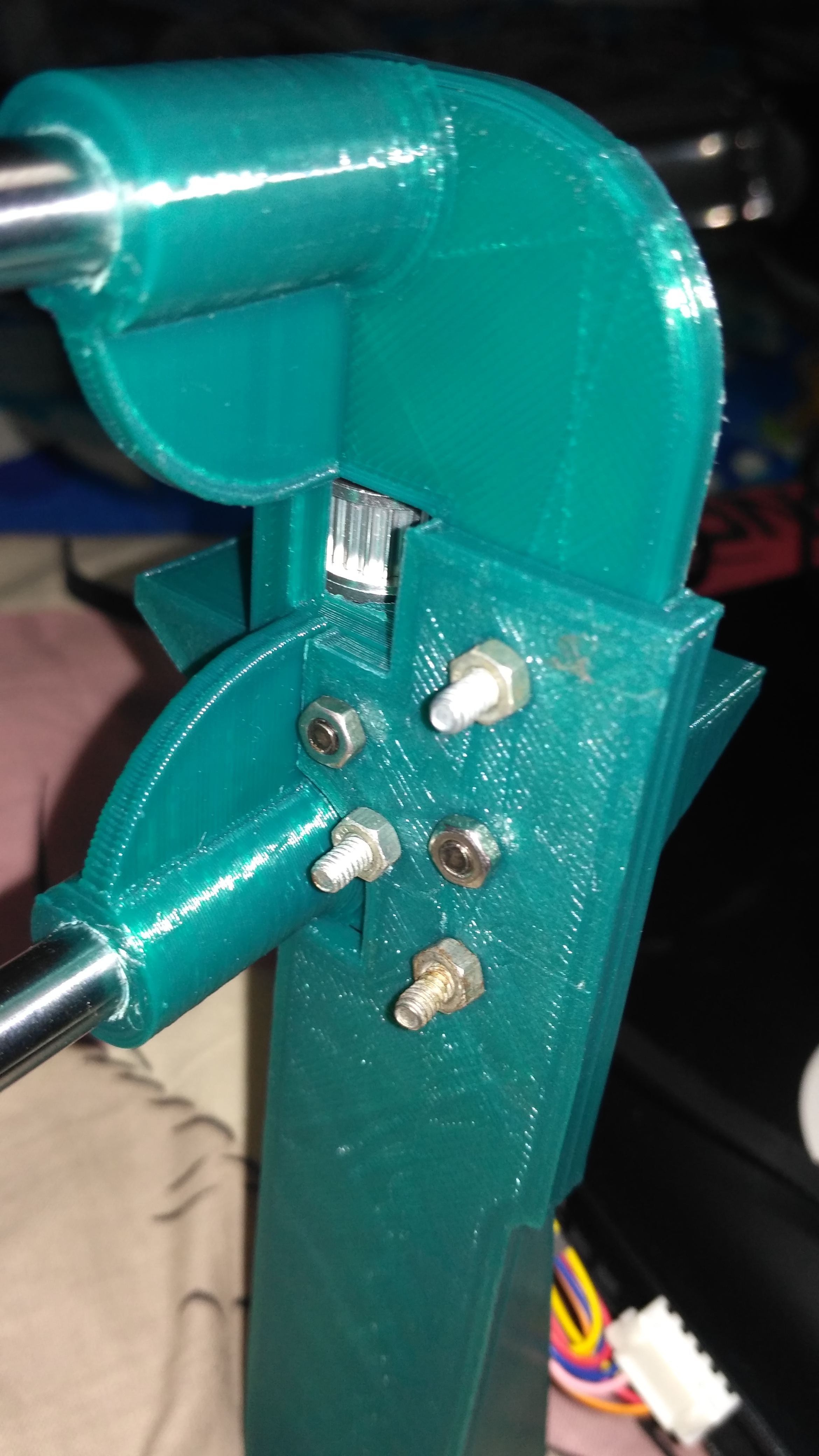
- First, fasten the stepper motor to the X-axis motor mount using two M3 12mm bolts and nuts. Fasten a GT2 16 teeth pulley onto the motor axle by tightening both the grub screws.
- Now insert the pulley onto the X-axis pulley holder using an M4 40mm bolt as the axle of the pulley as seen in the picture. Remove both the grub screws from this pulley.
- Fasten the Motor mount along with the motor to the right and the pulley holder to the left of the X-axis assembly using three M3 30mm bolts and nuts on each side as shown in the picture.
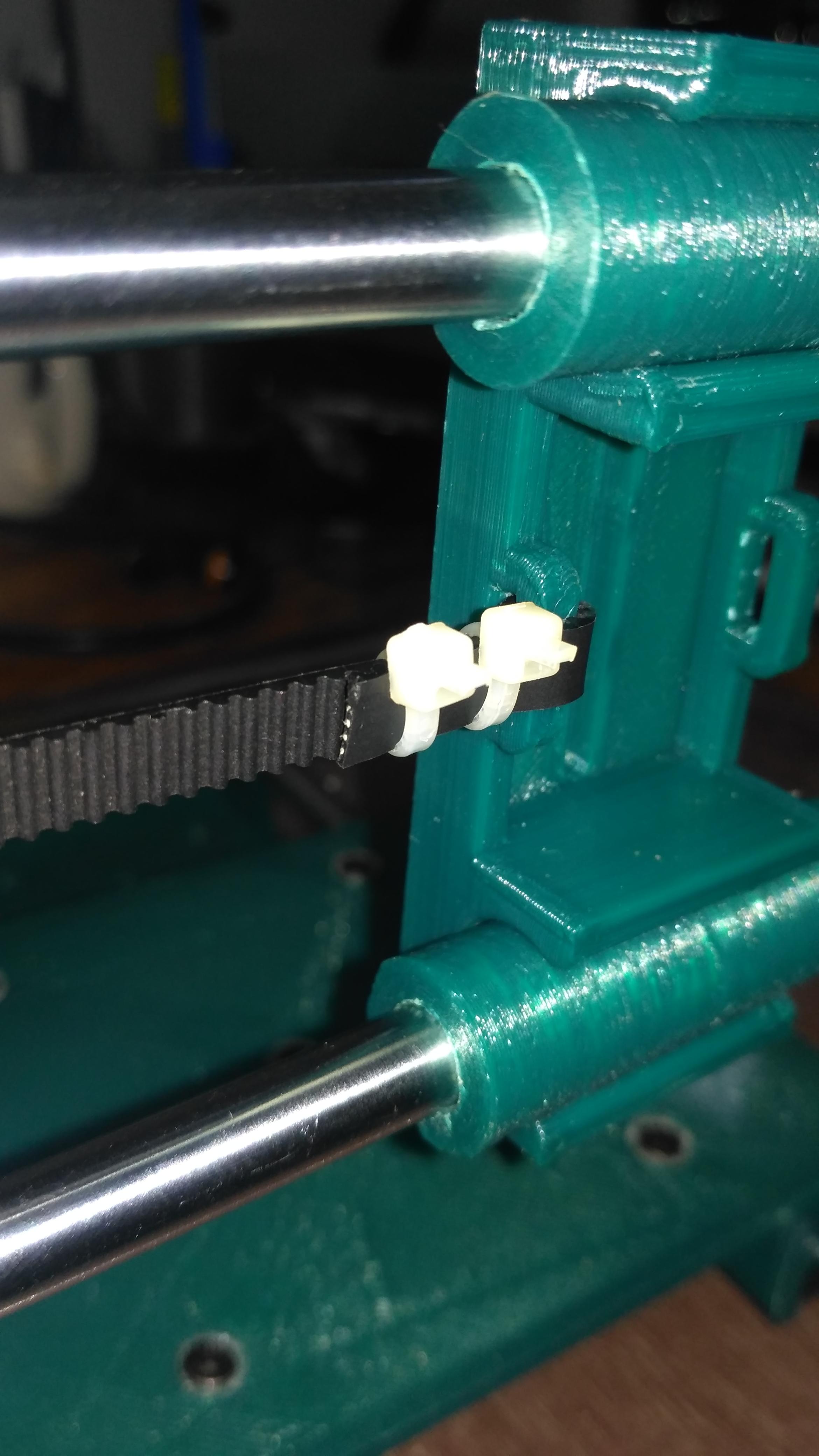
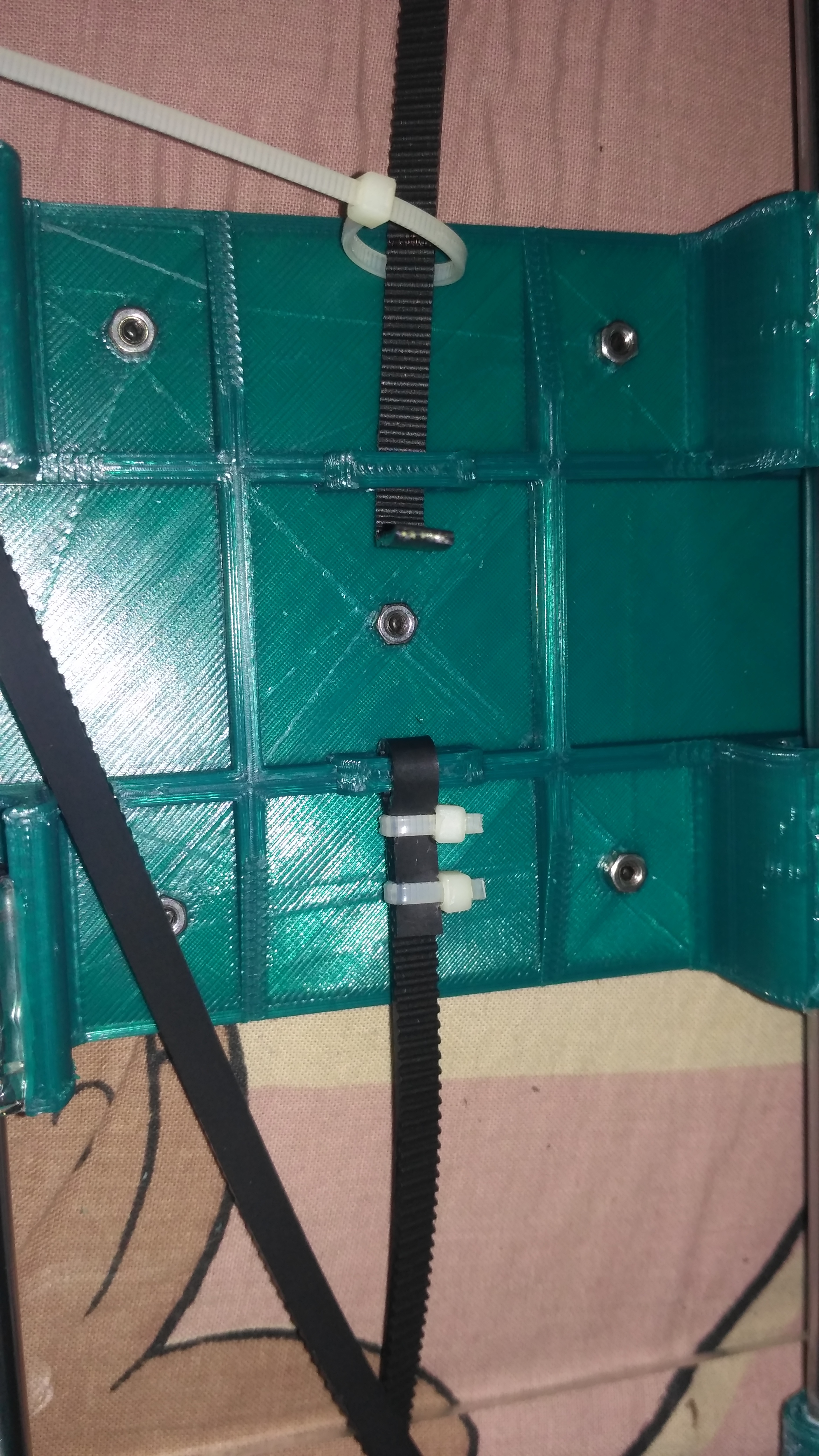
- Tie one end of the timing belt to one of the slots provided for it on the X-axis carriage using cable ties.
- Run the other end of the belt through both the pulleys and back to the second slot on the X-axis carriage and tie it using cable ties. Make sure that the belt is not too tight nor too loose. It should be springy to the touch.
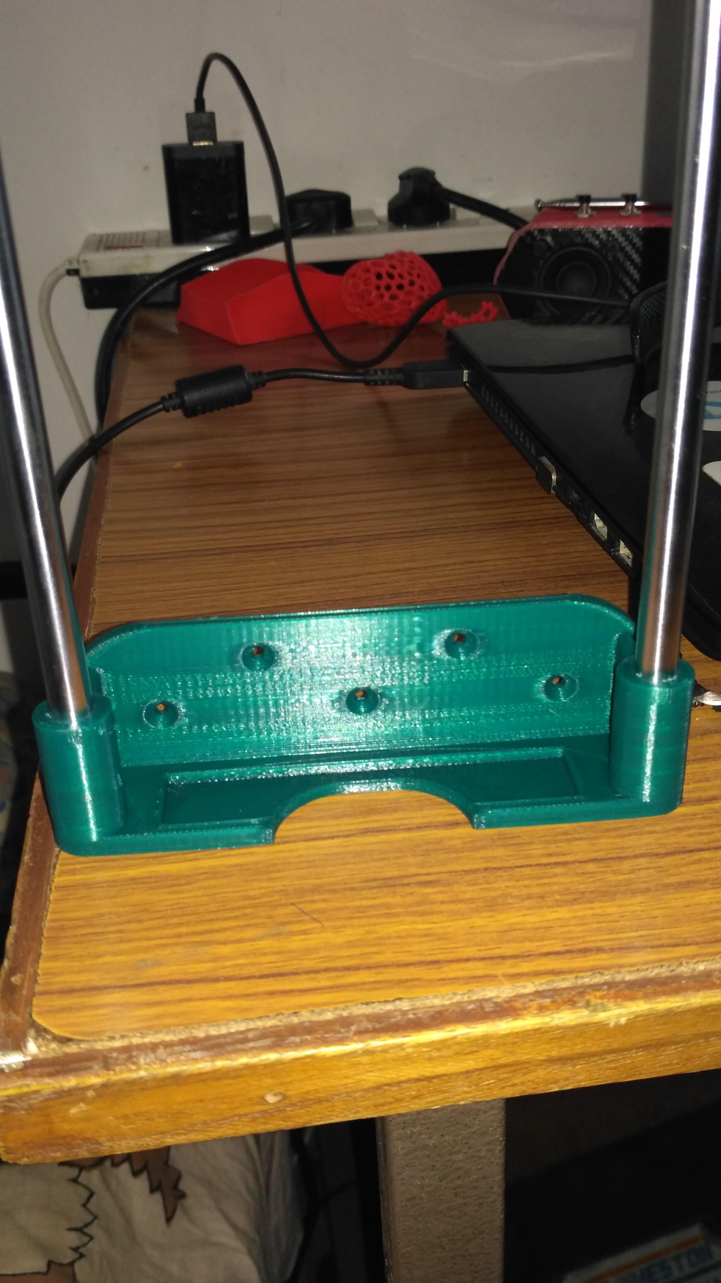
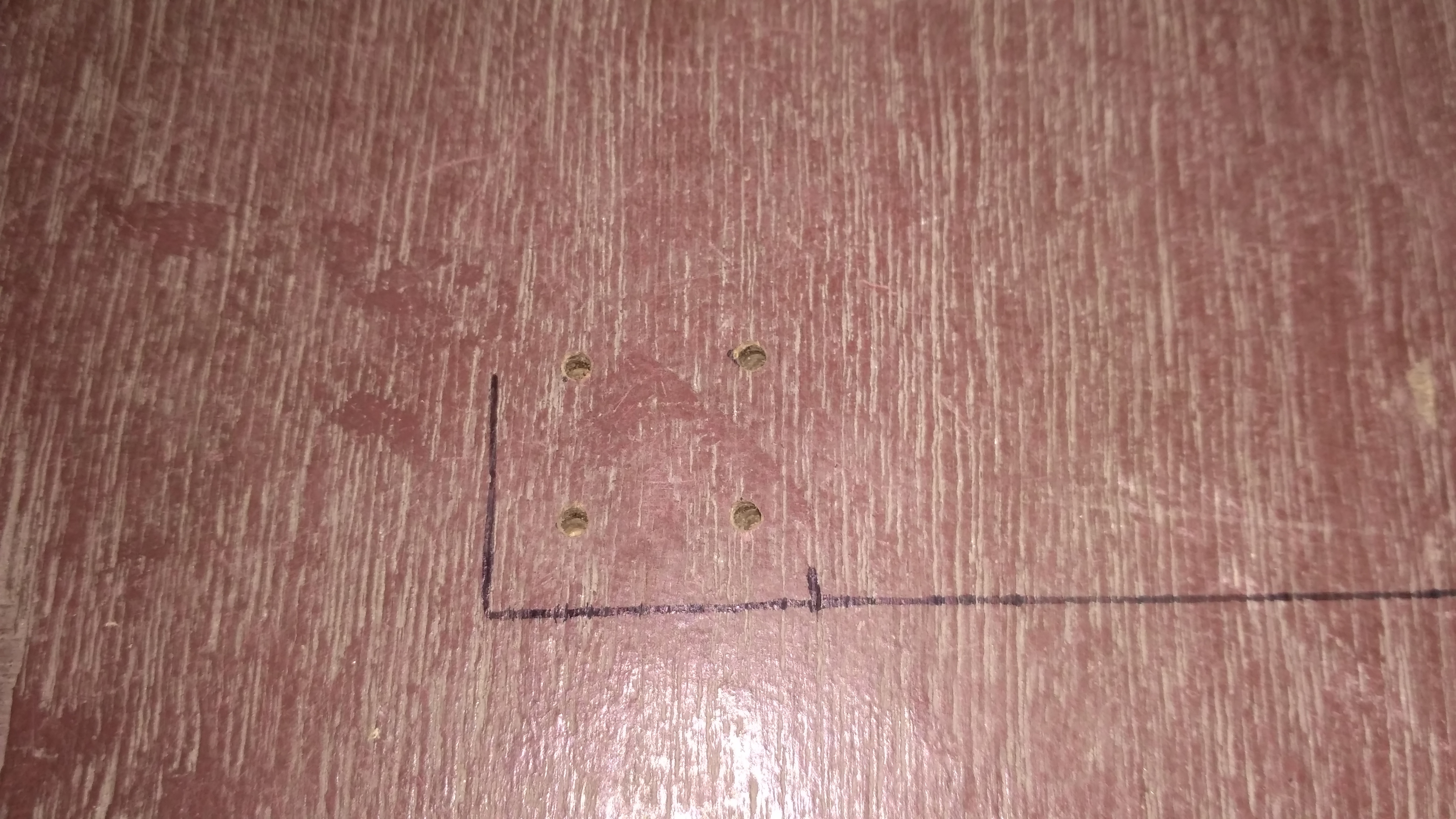
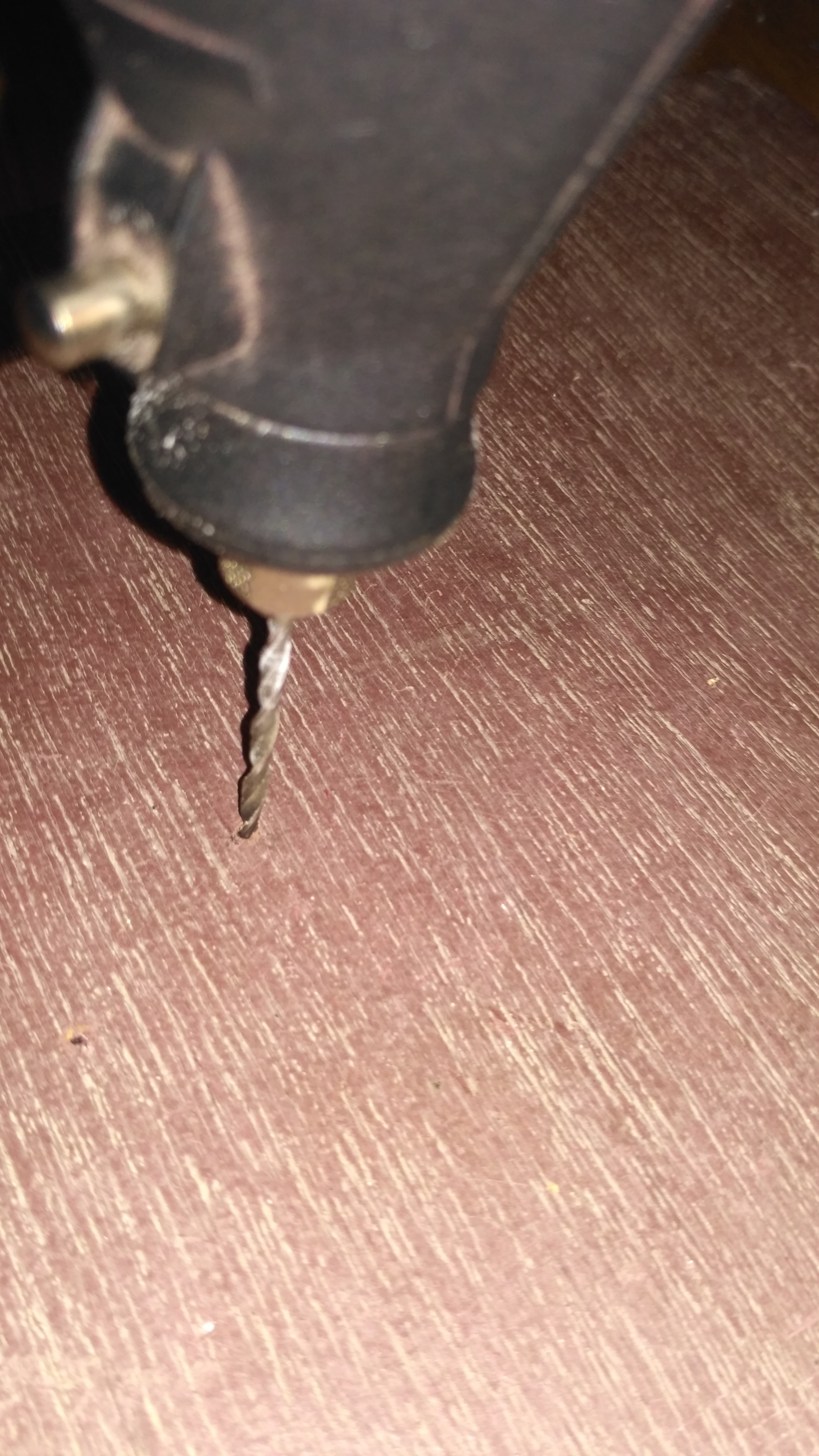
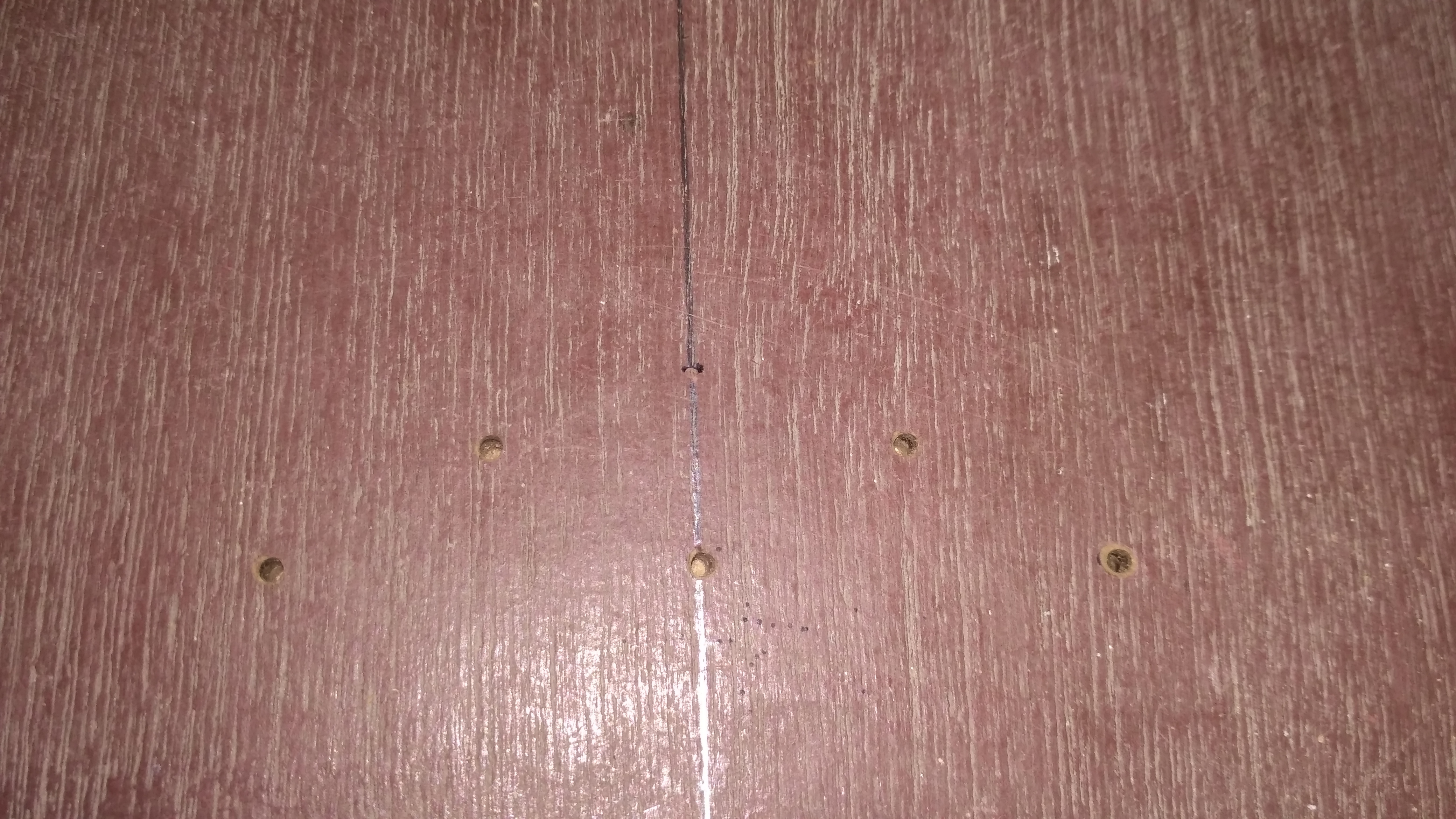
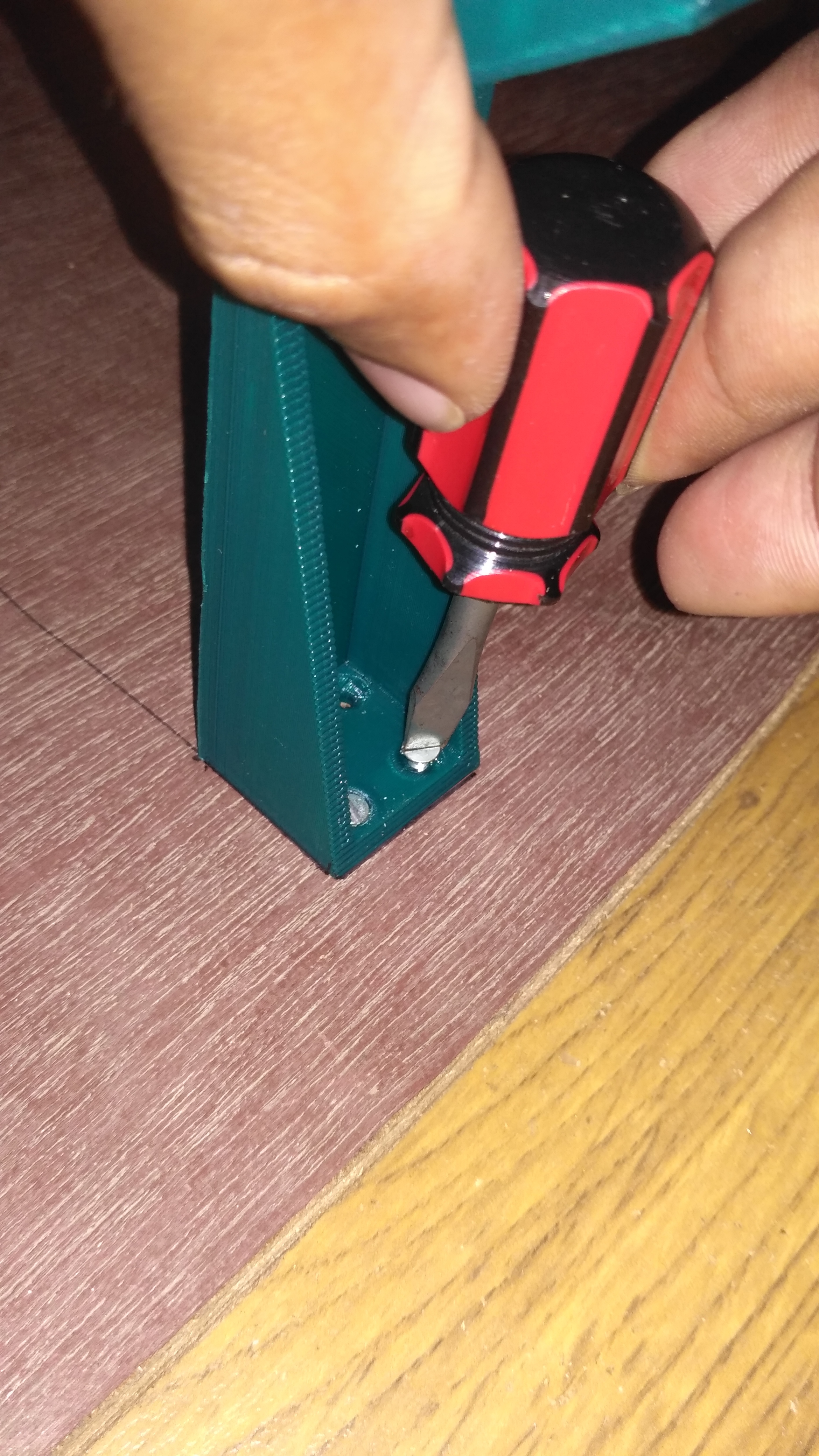
BASE BOARD PREPARATION AND X AXIS MOUNTING
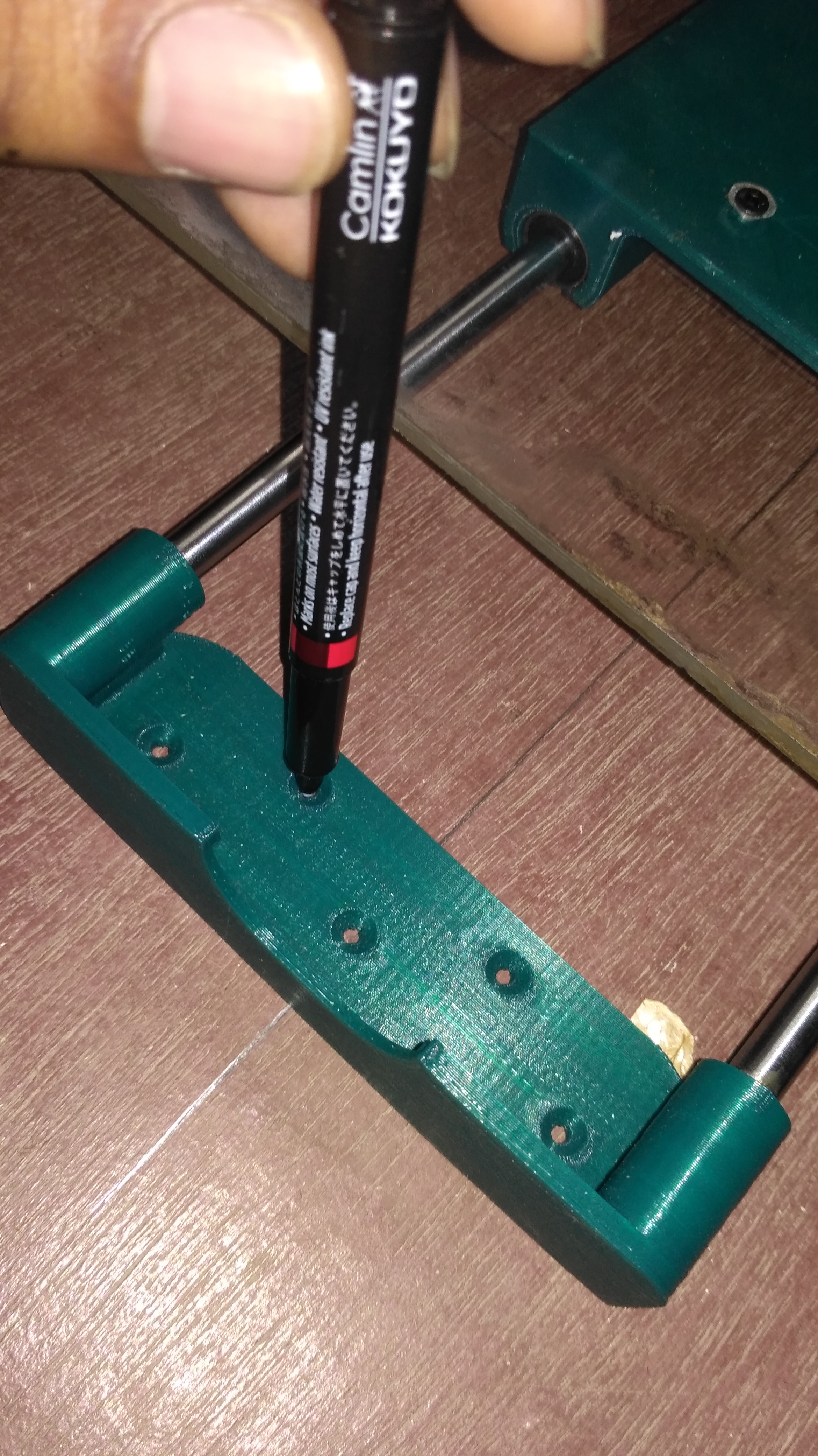
.png)
- First, draw a huge perfect cross in the middle of the baseboard
- Align the X-axis assembly along the X-axis of the cross as seen in the picture.
- Mark the screw hole positions using a marker.
- Do the same for Y-axis as well.
- Drill the holes using a 3mm drill bit.
- Screw the X-axis assembly to the baseboard.
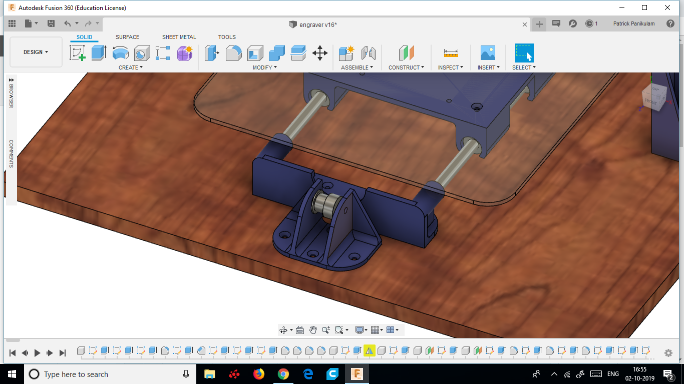
MOUNTING THE Y-AXIS SETUP
.png)
This is a tricky step, so please refer to the assembly file for better understanding and then follow these steps
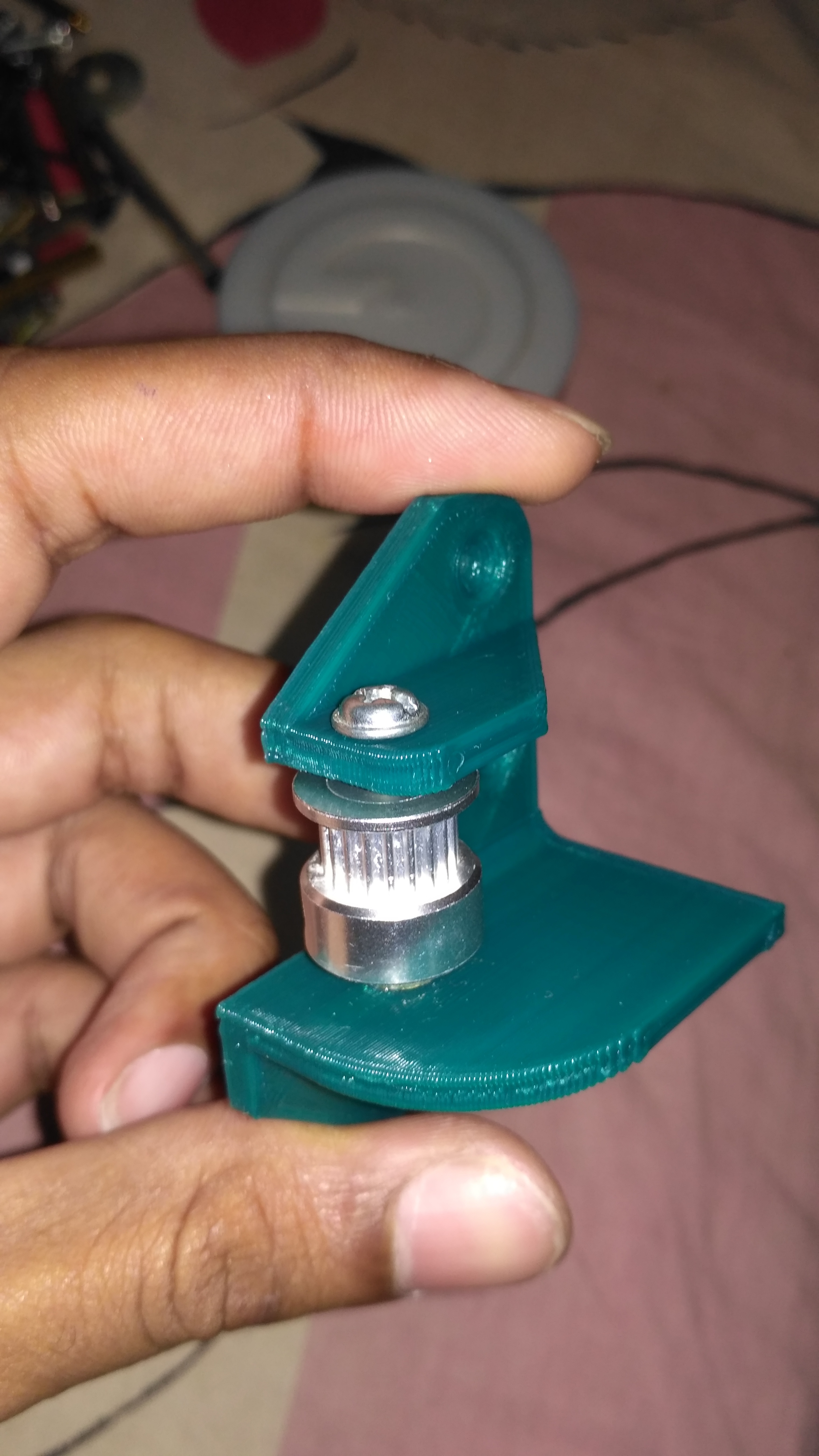
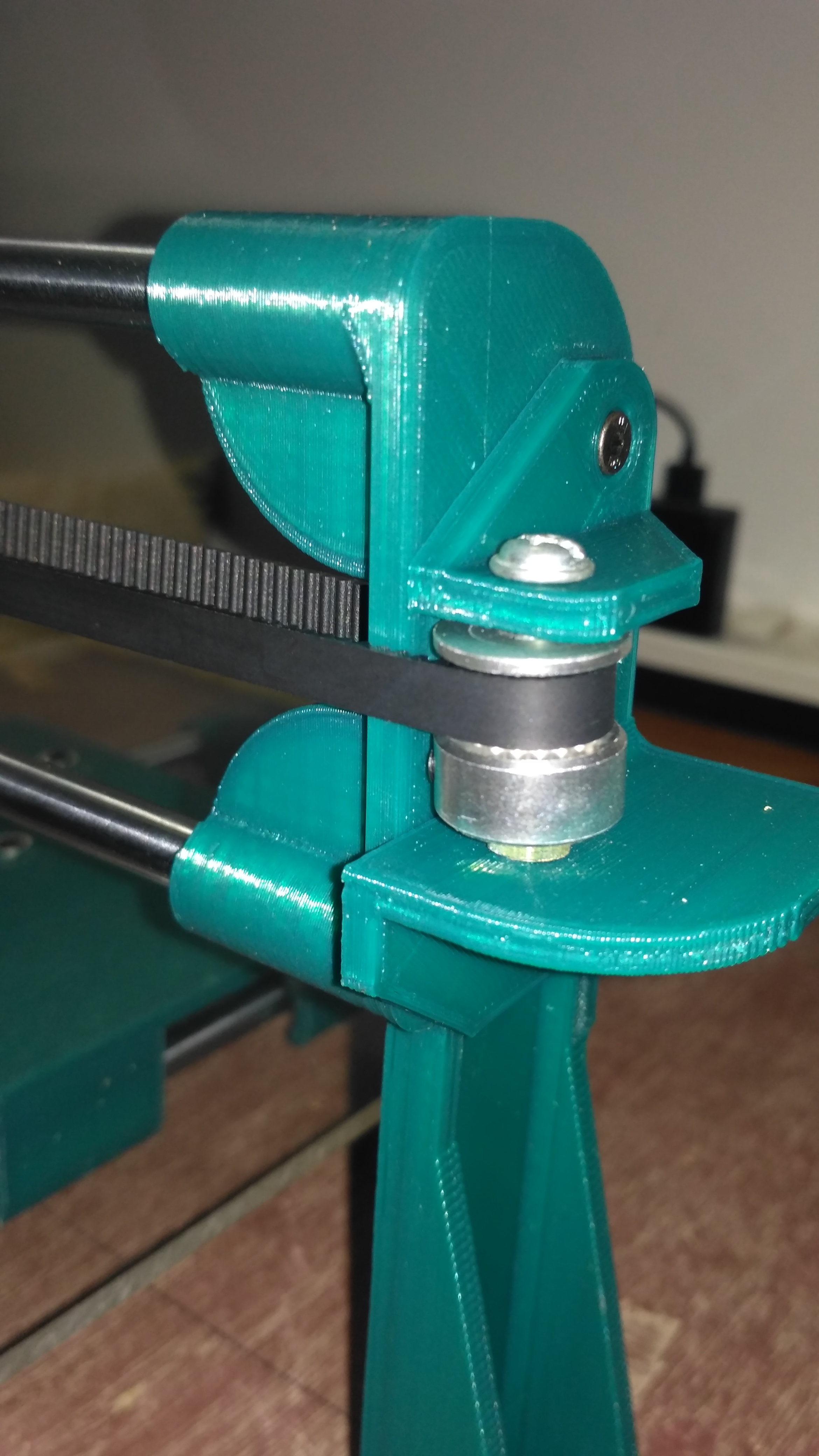
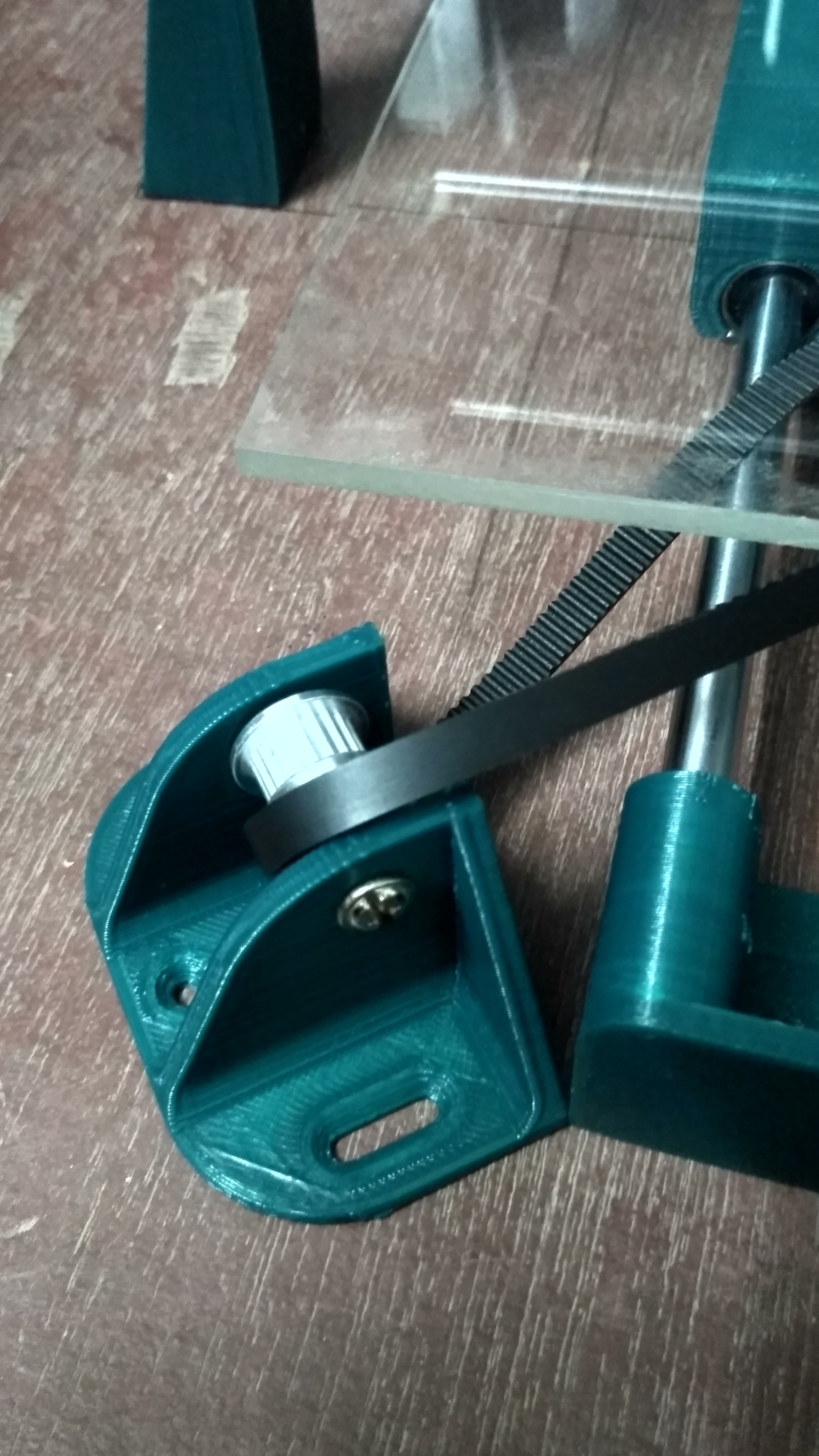
- Assemble the pulley holder using the Y-axis pulley holder, the pulley, M4 40mm bolt/nut, and metallic washers as seen in the first two pictures.
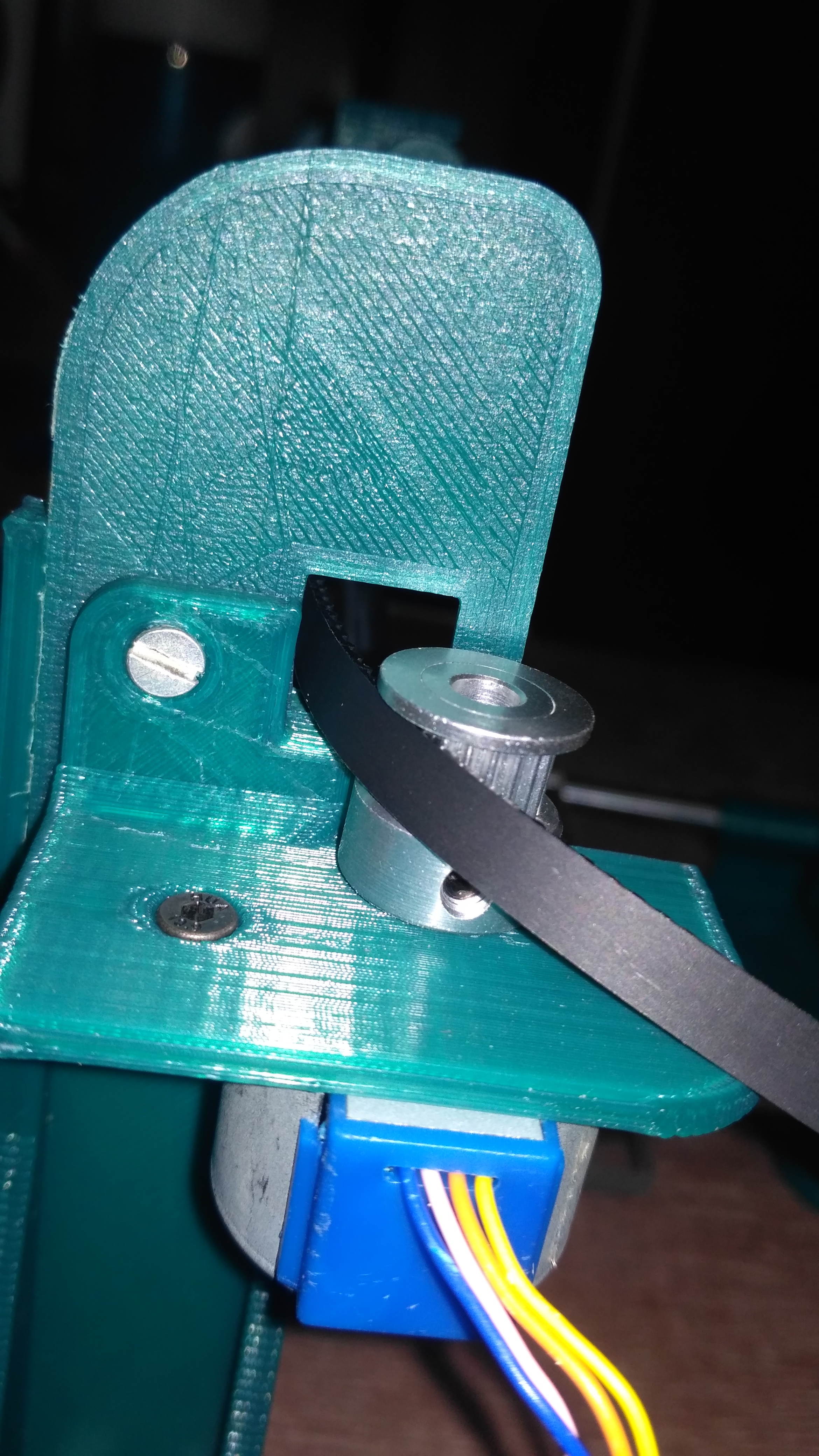
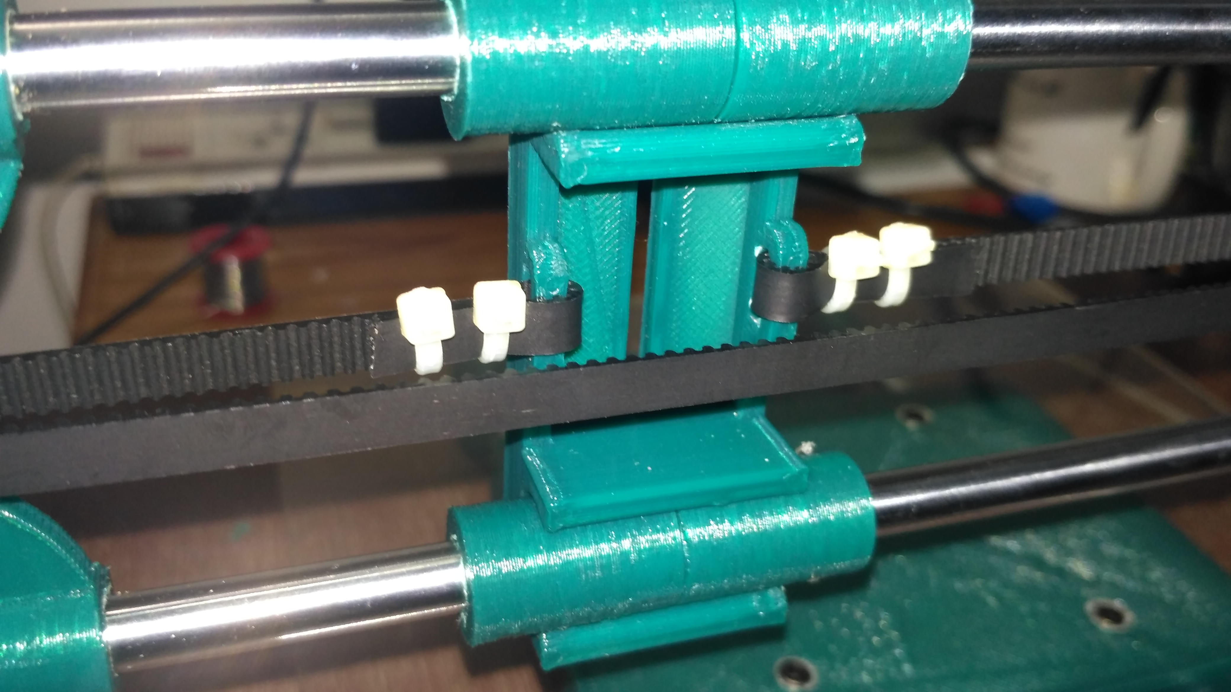
- Now tie one end of the timing belt to one of the slots beneath the Y-axis carriage.
- Run the free end of the belt through the pulley assembly which you made earlier and then tie it to the second slot provided beneath the Y-axis carriage.
- Once these 3 steps are done we can screw the Y-axis assembly to the plywood base referring the holes for this we drilled earlier after marking the hole positions.
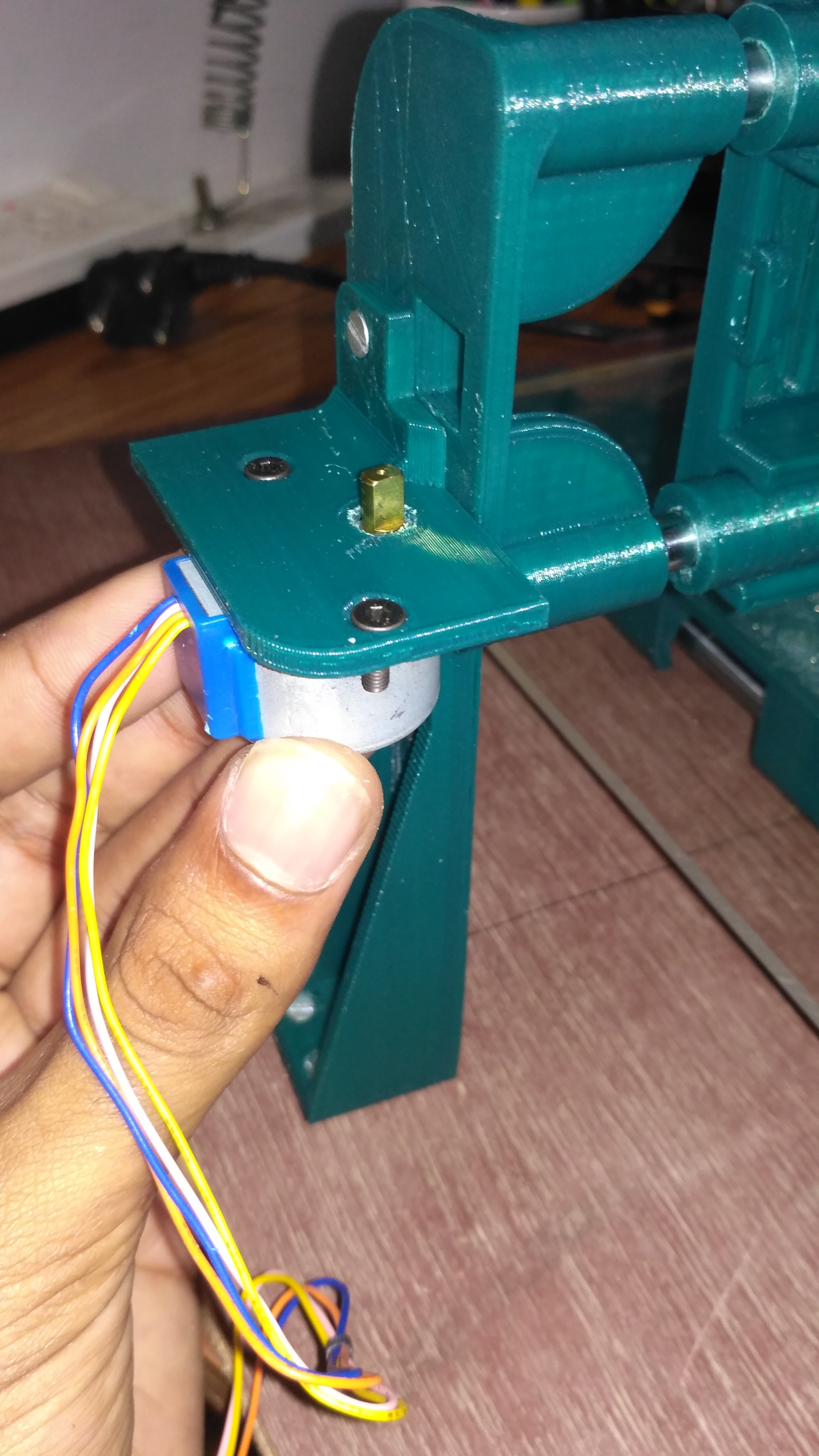
- Fasten the stepper motor to the Y-axis motor mount using two M3 12mm bolts and nuts.
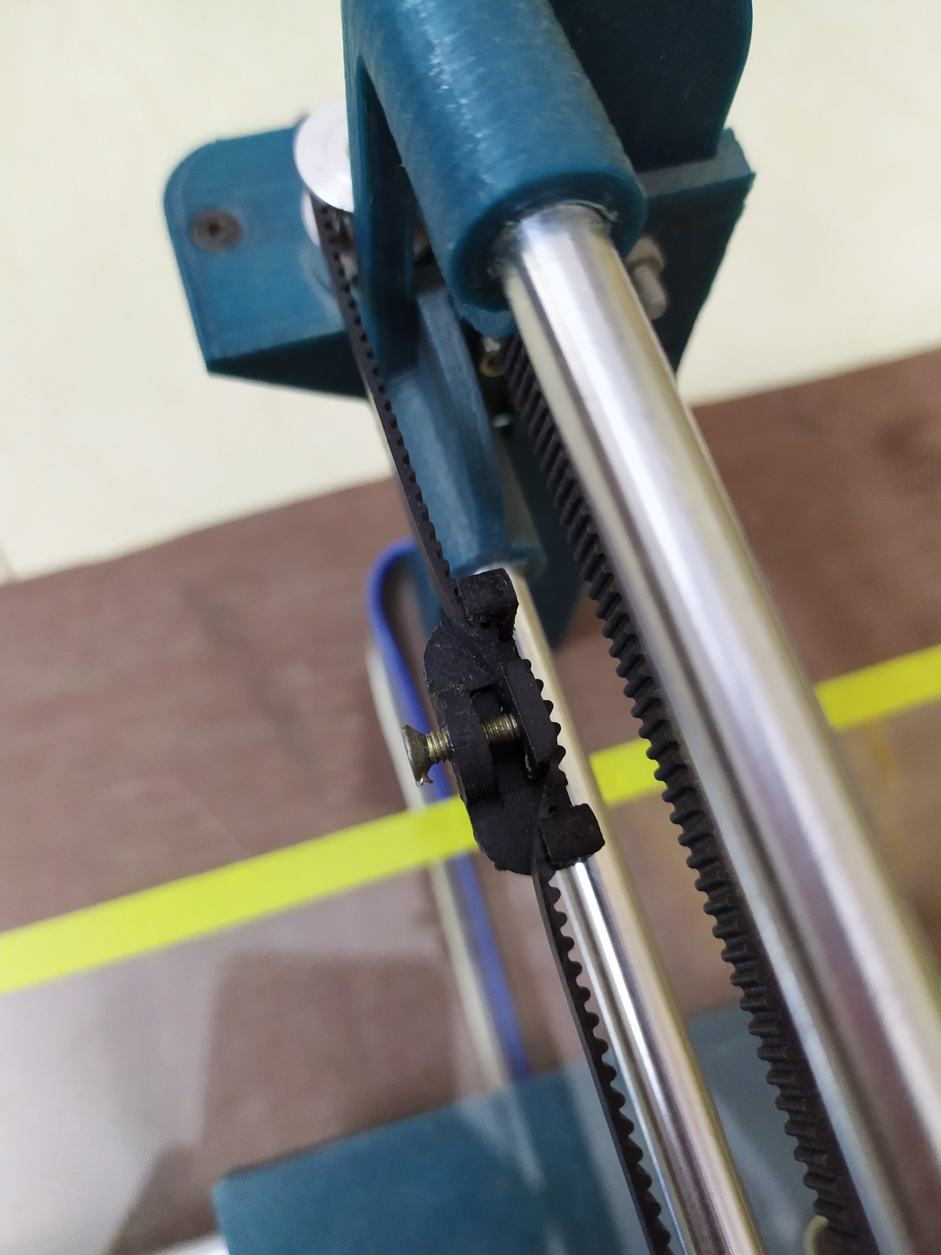
- Now screw the Y-axis pulley holder and Motor mount to the plywood base. Do this after adjusting both sides to get the correct belt tension. It's okay even if it's not perfect as we will be adding an adjustable belt tensioner later on.
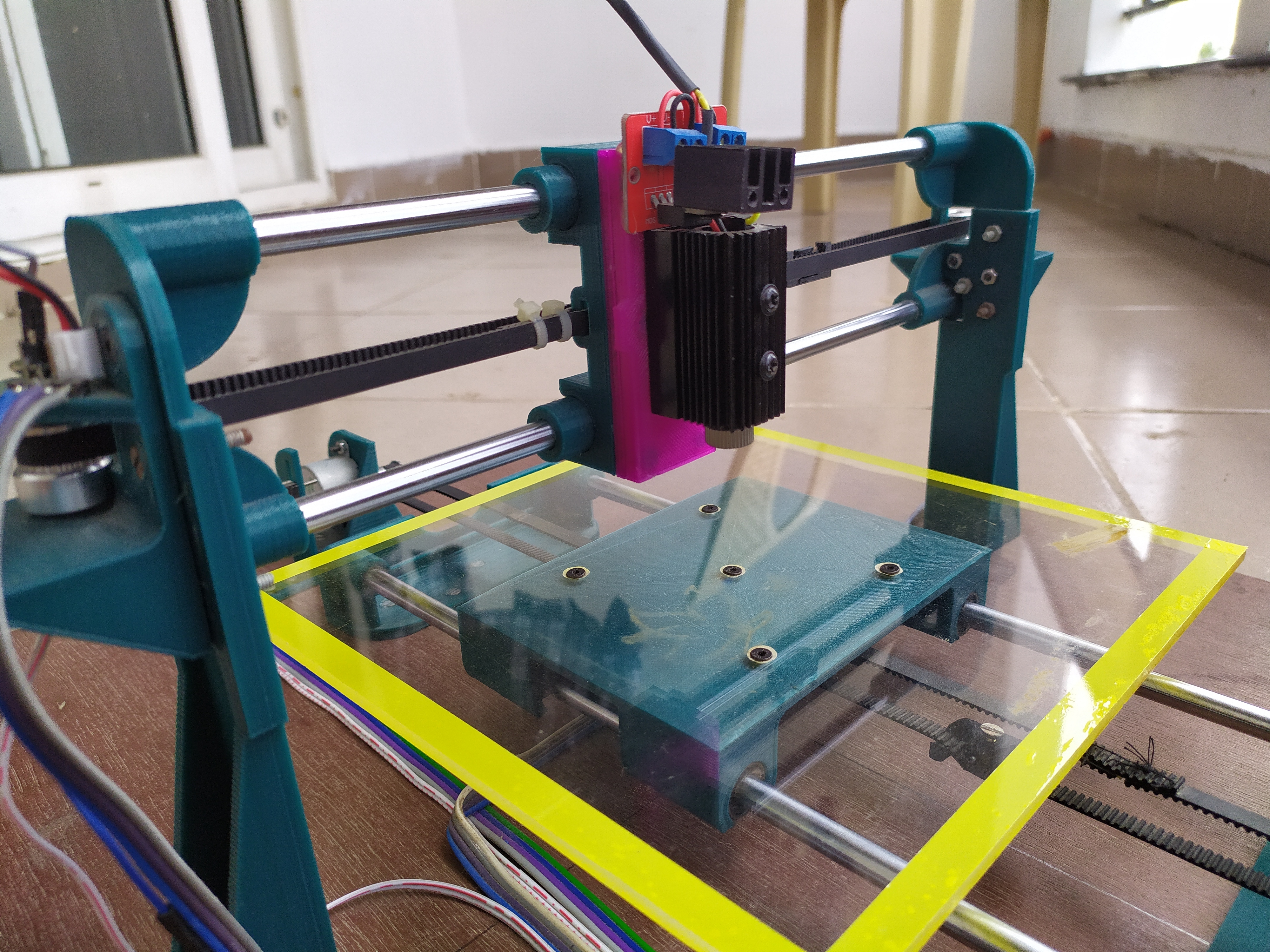
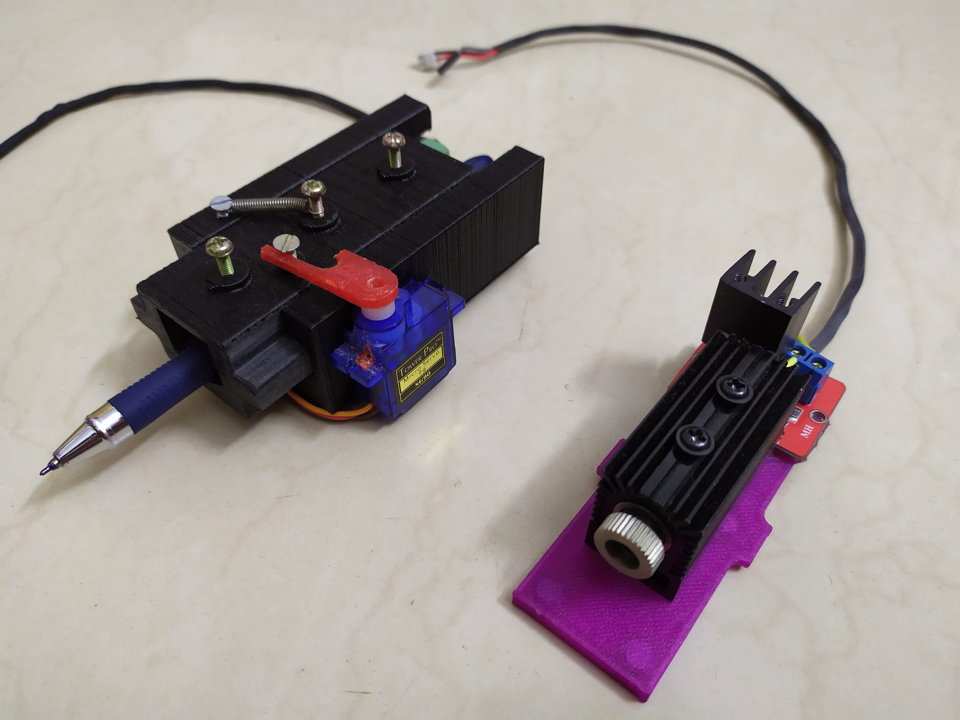
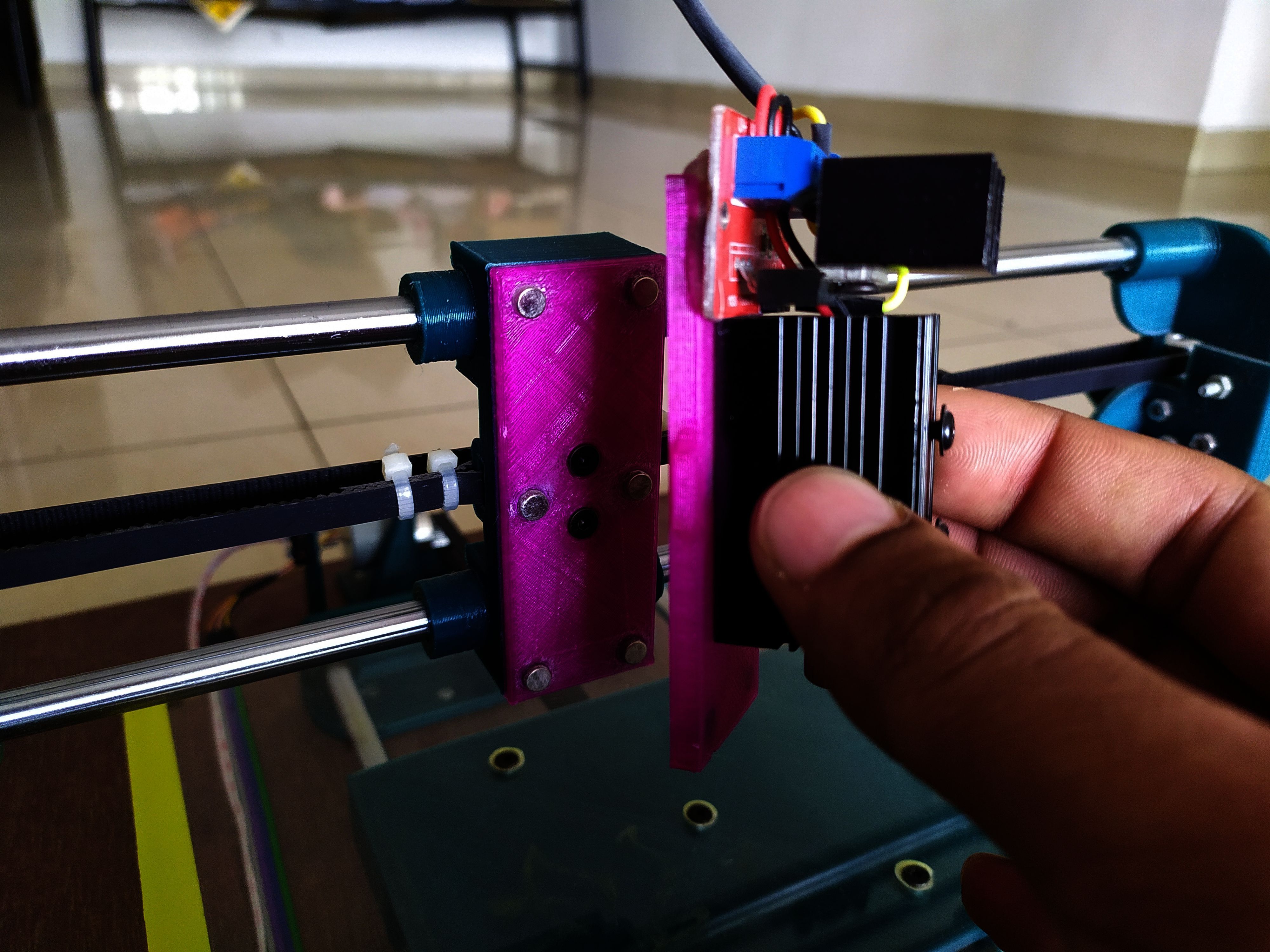
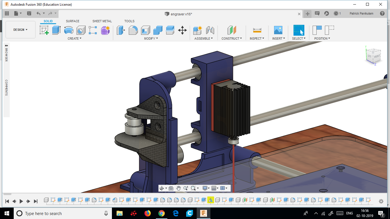
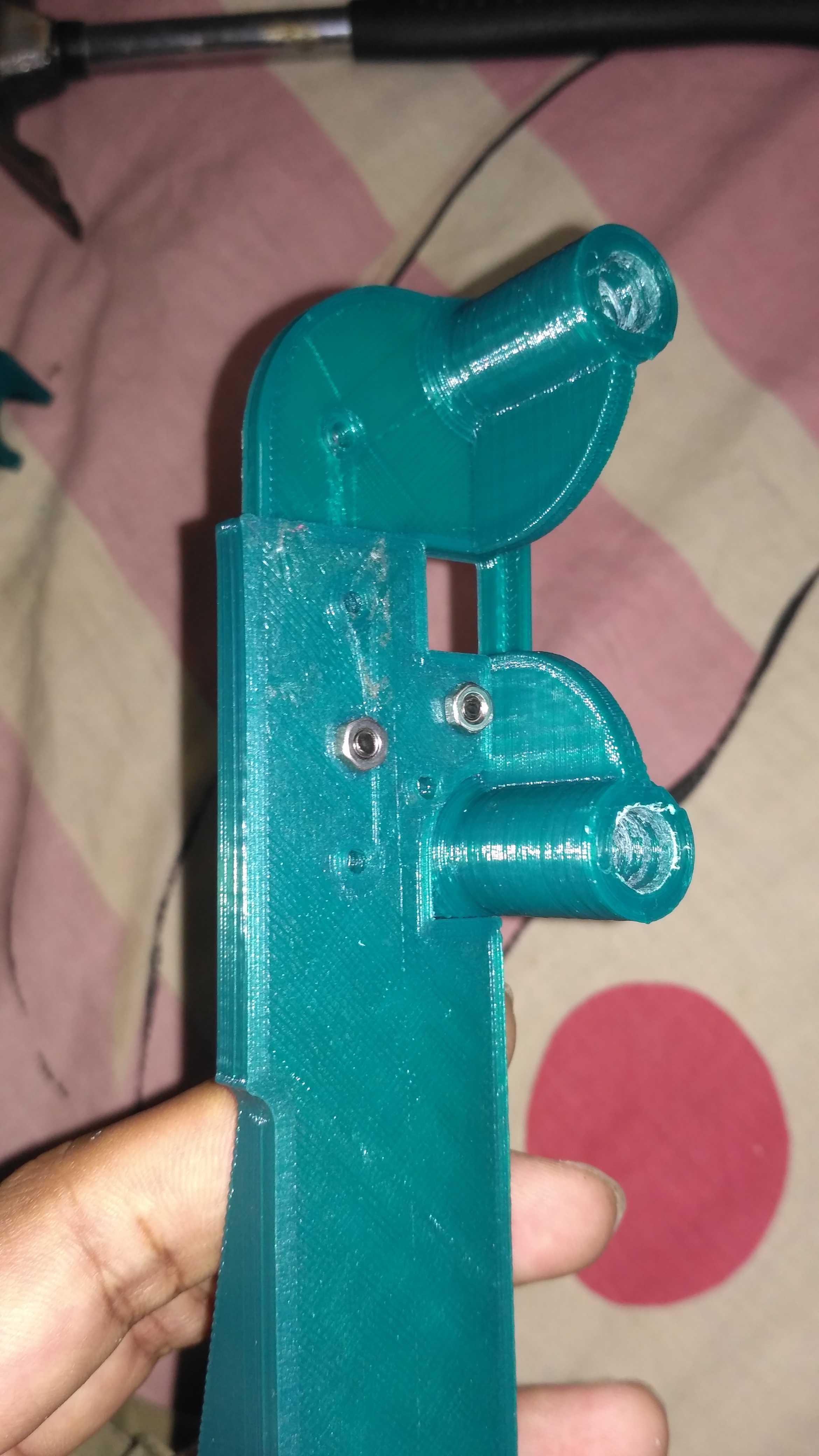
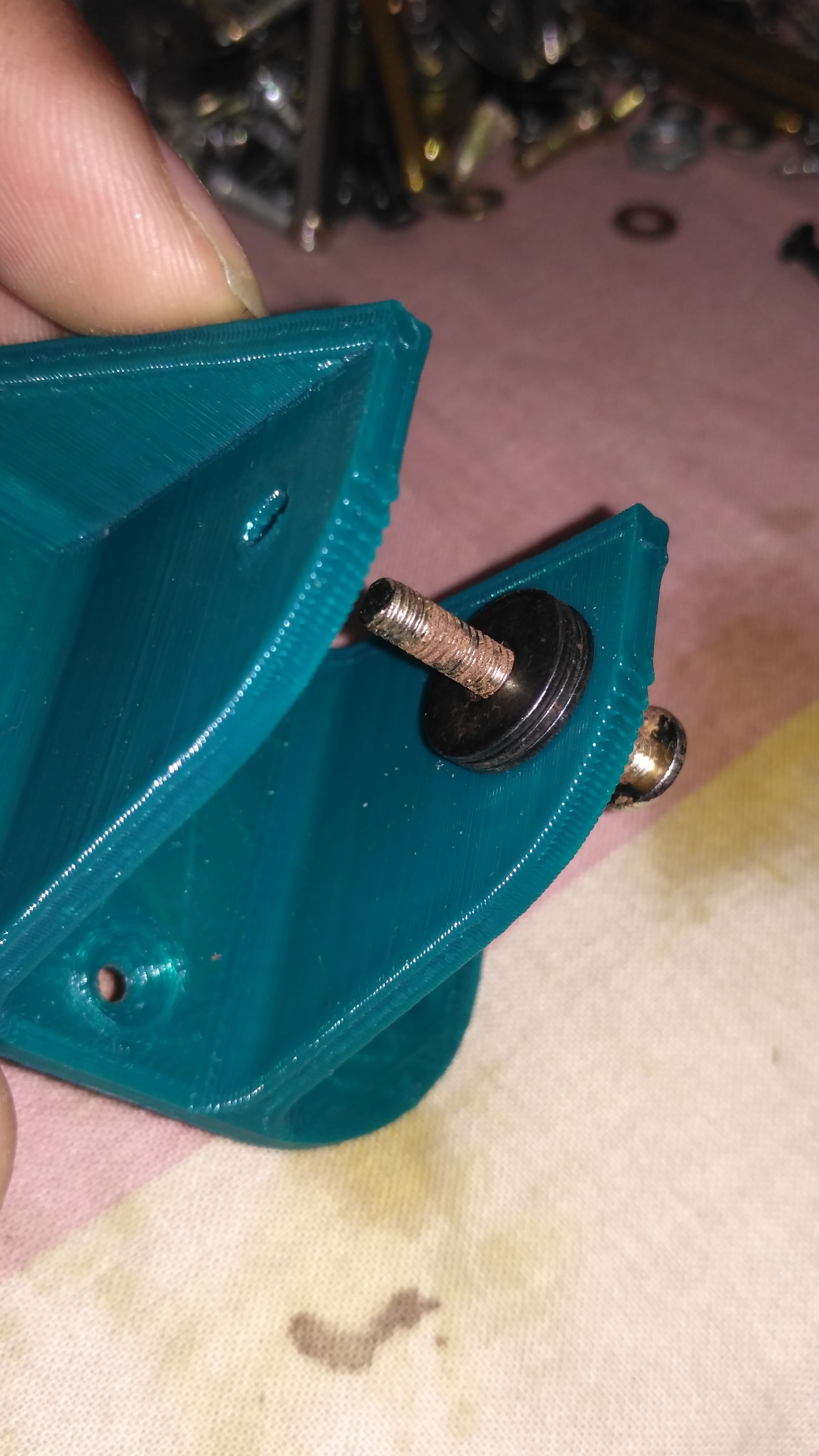
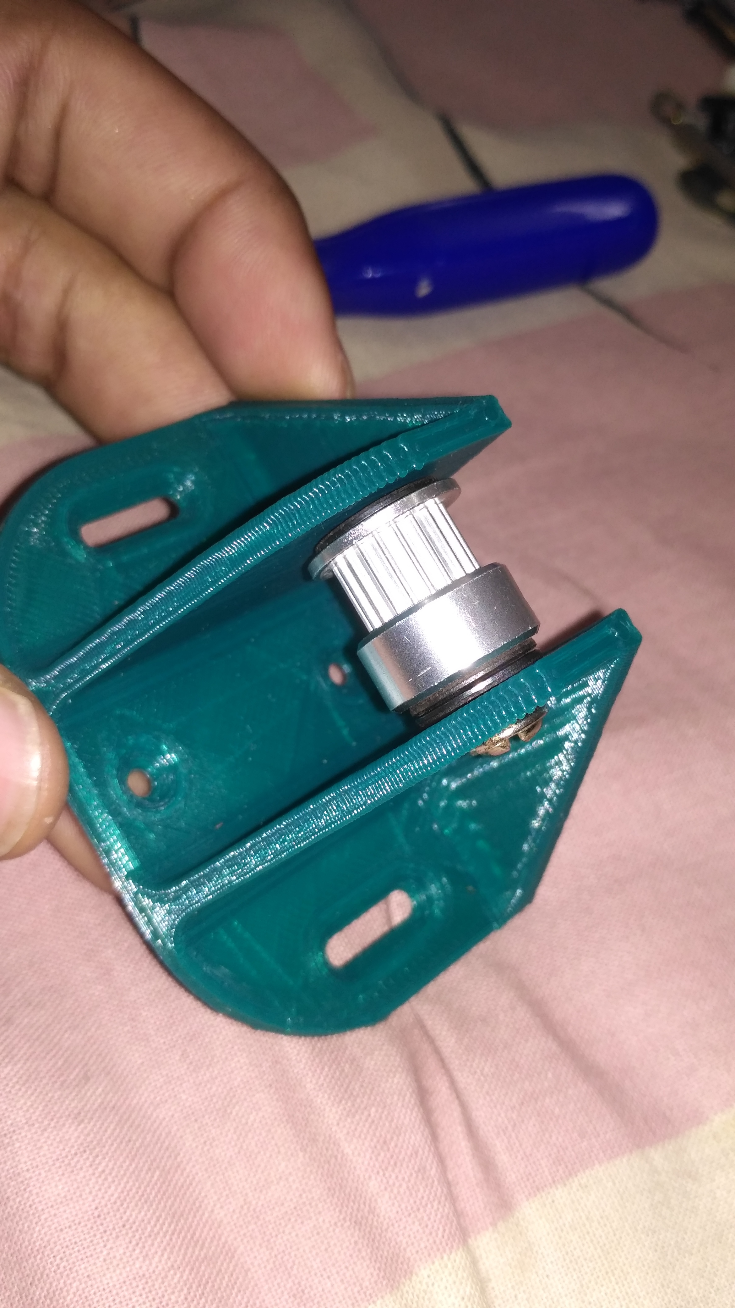
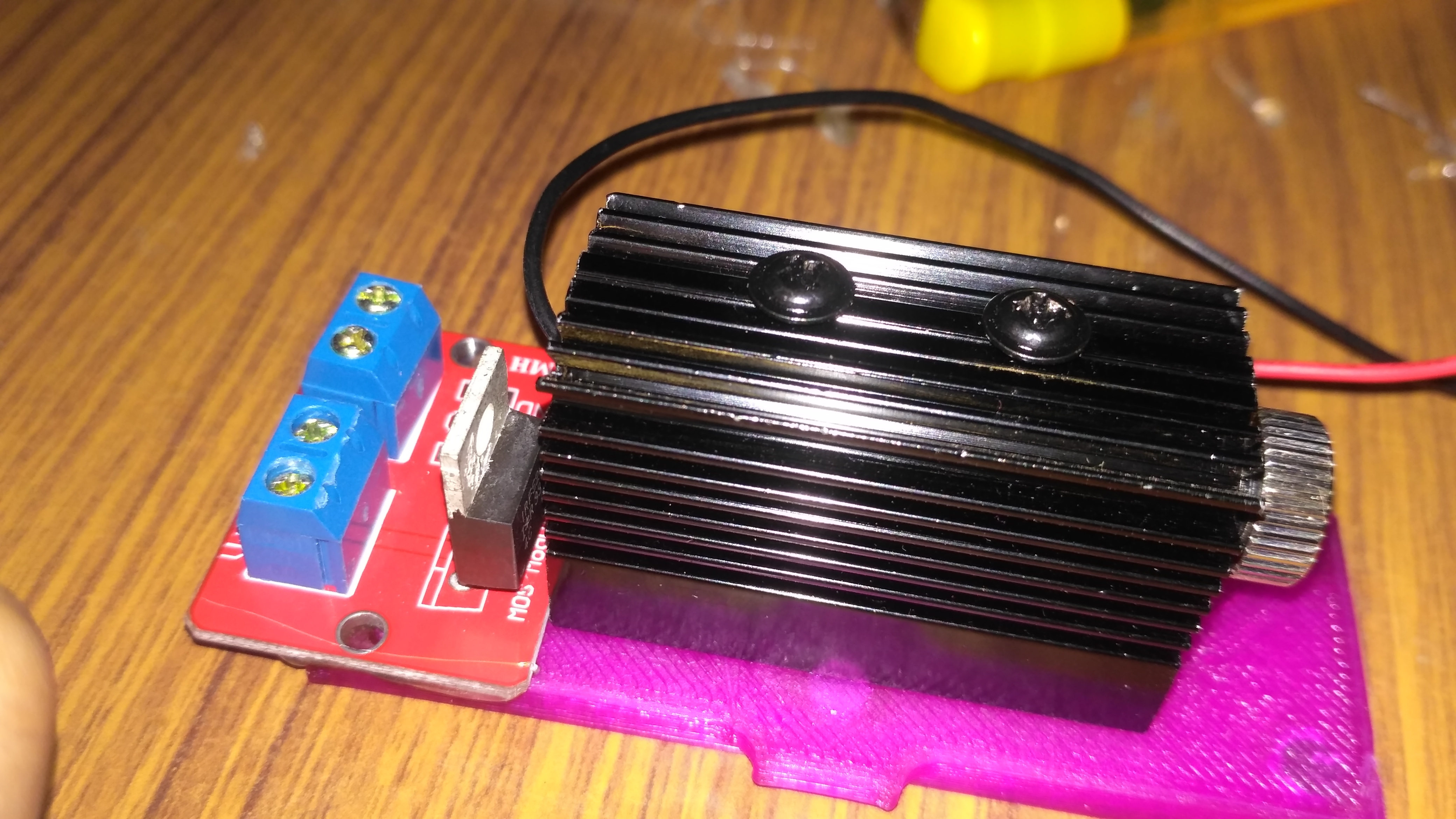
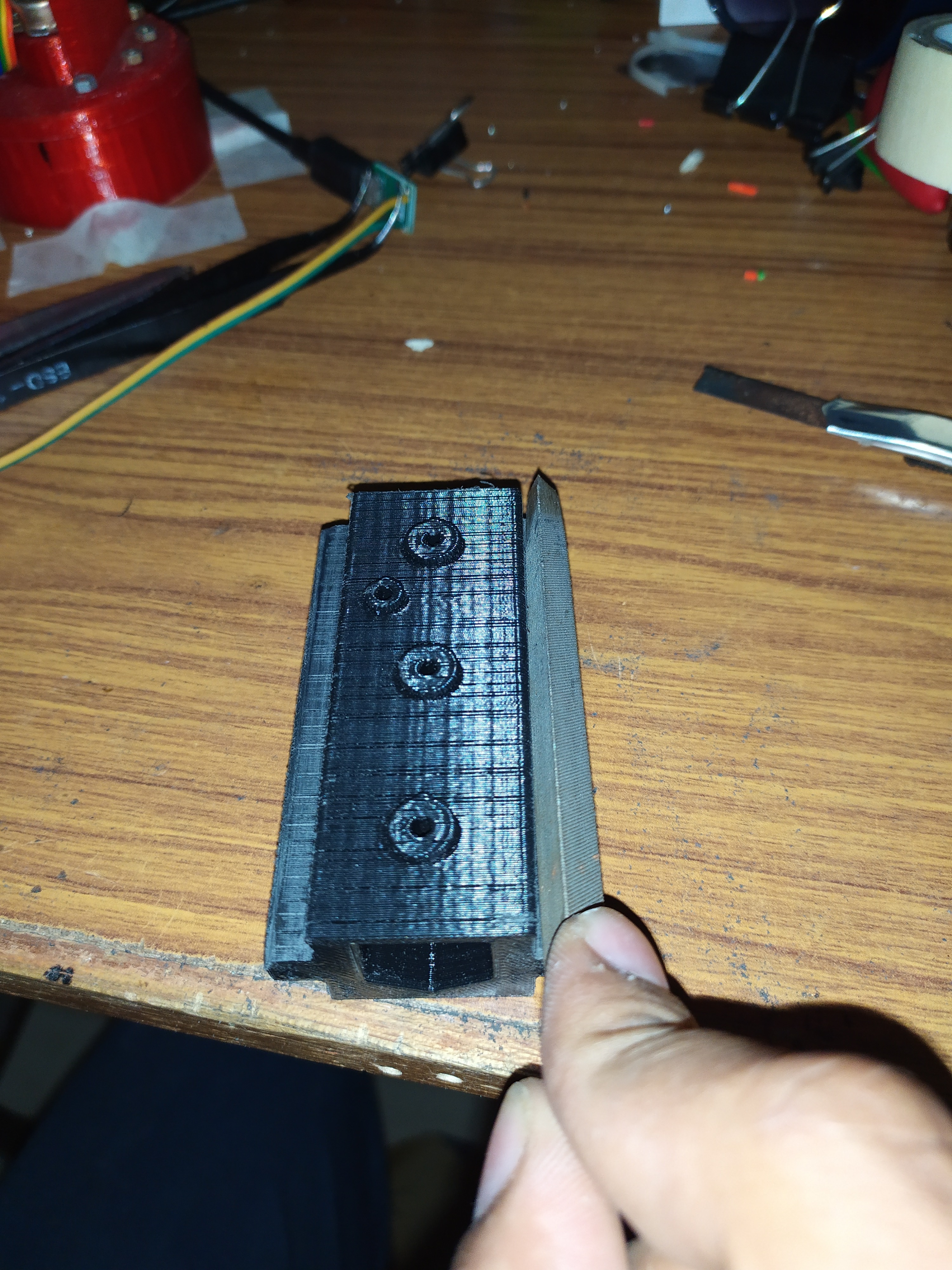
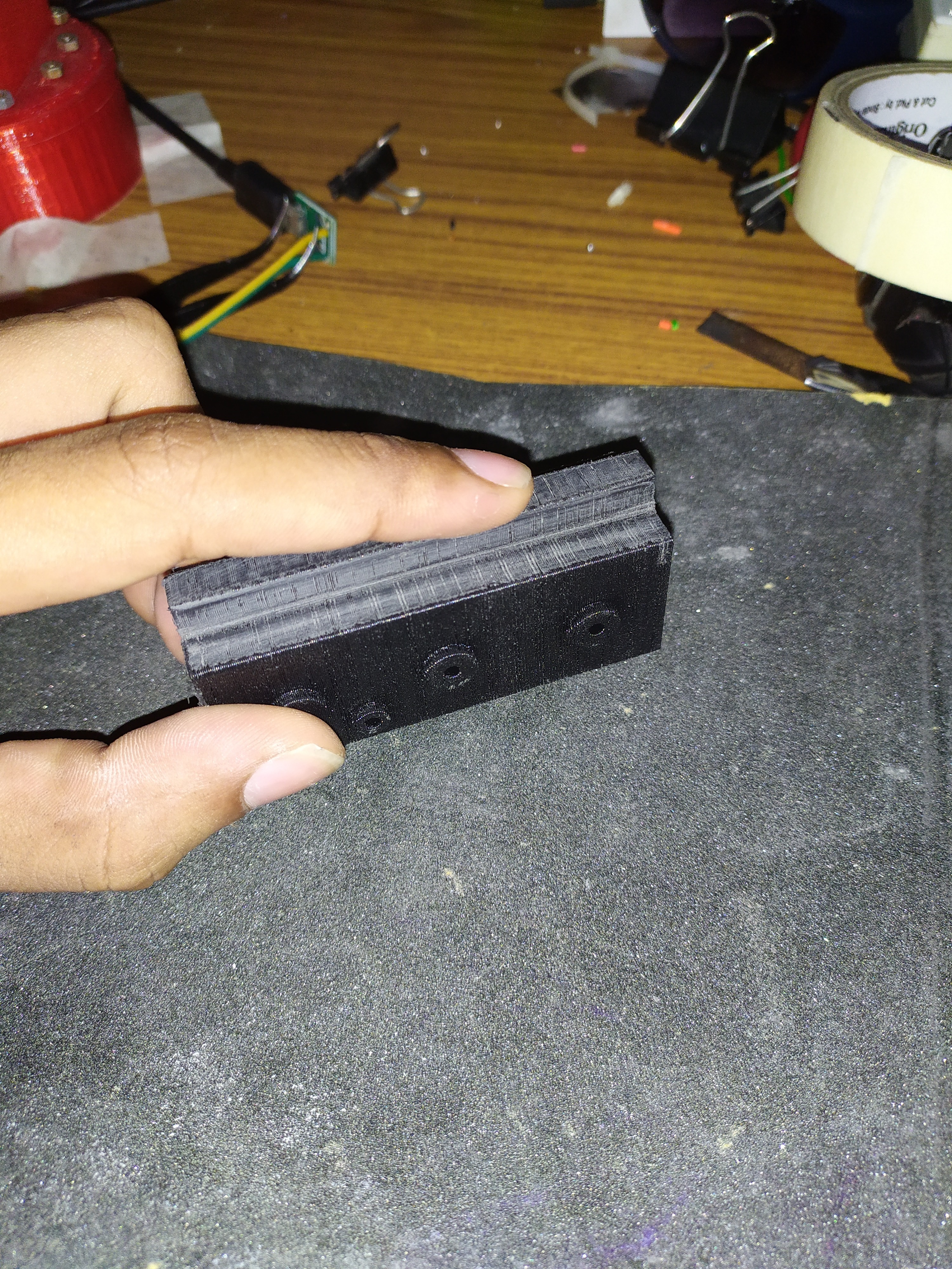
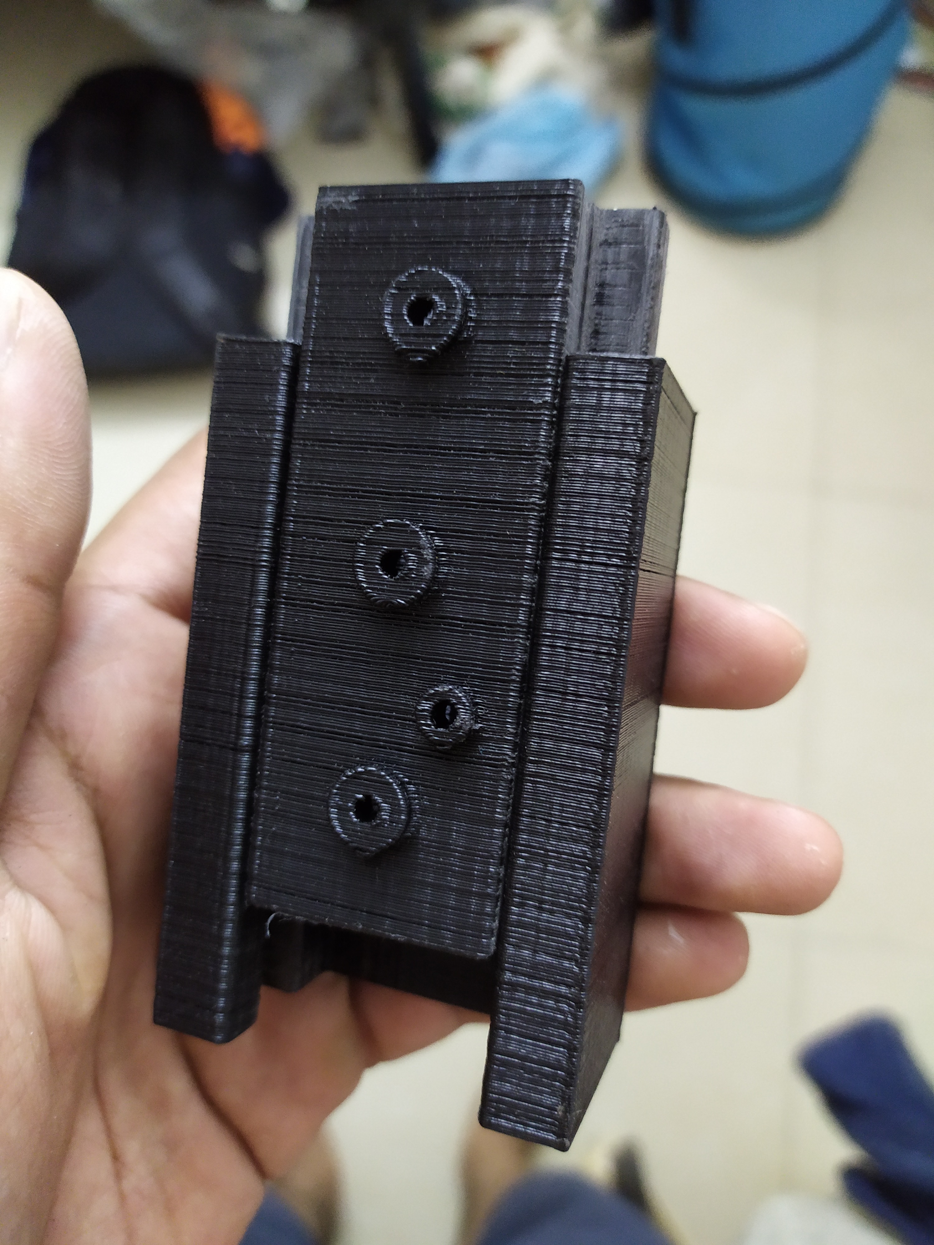
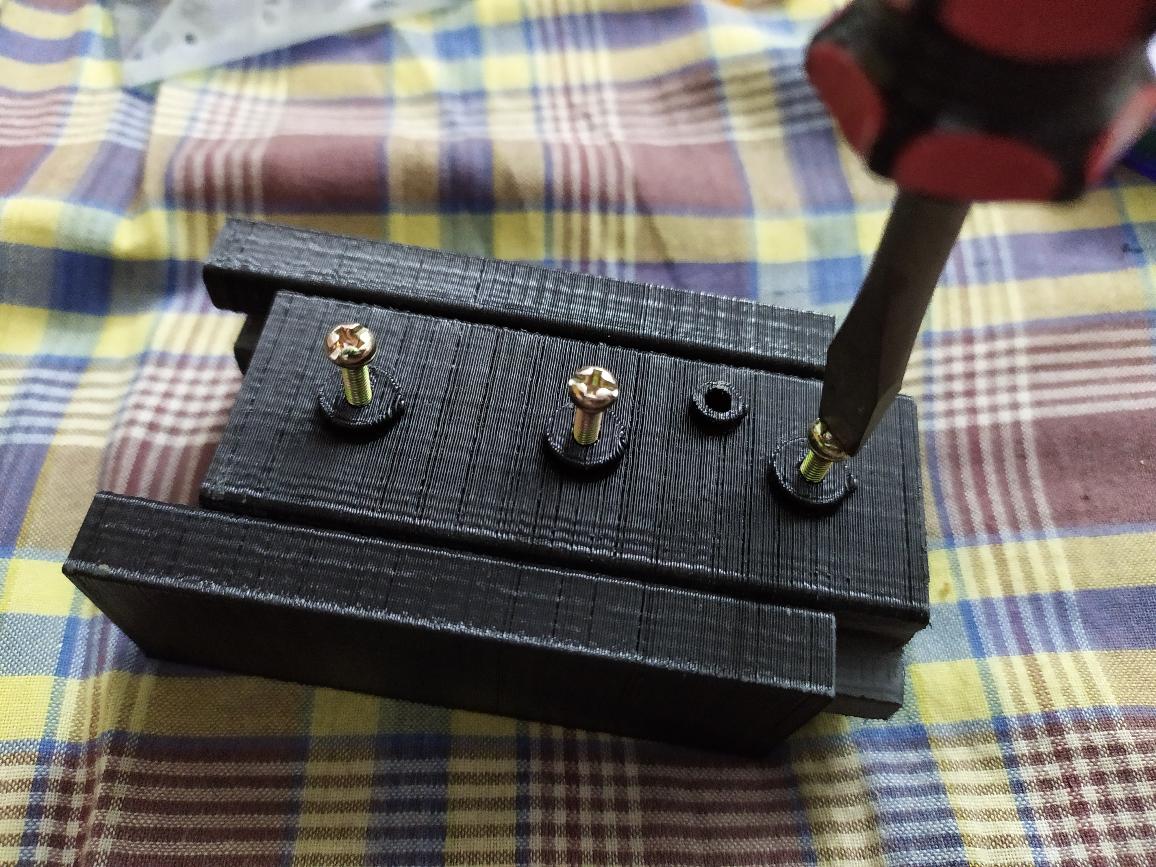
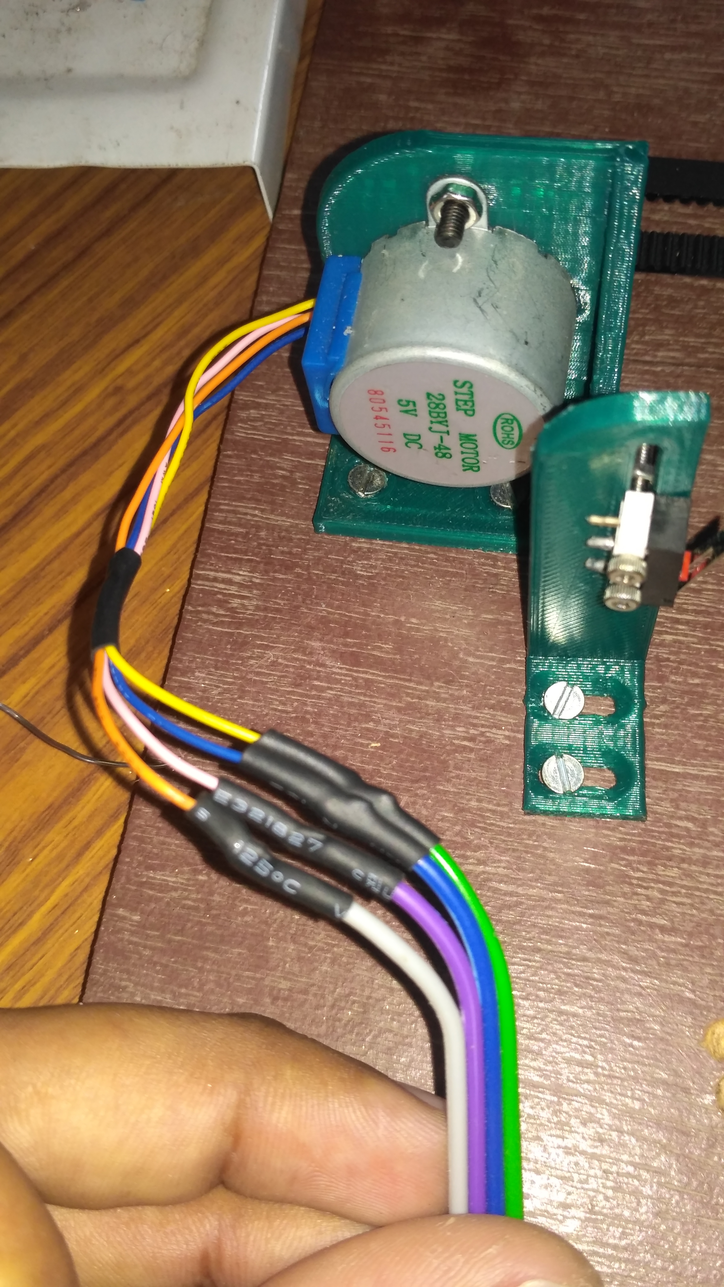
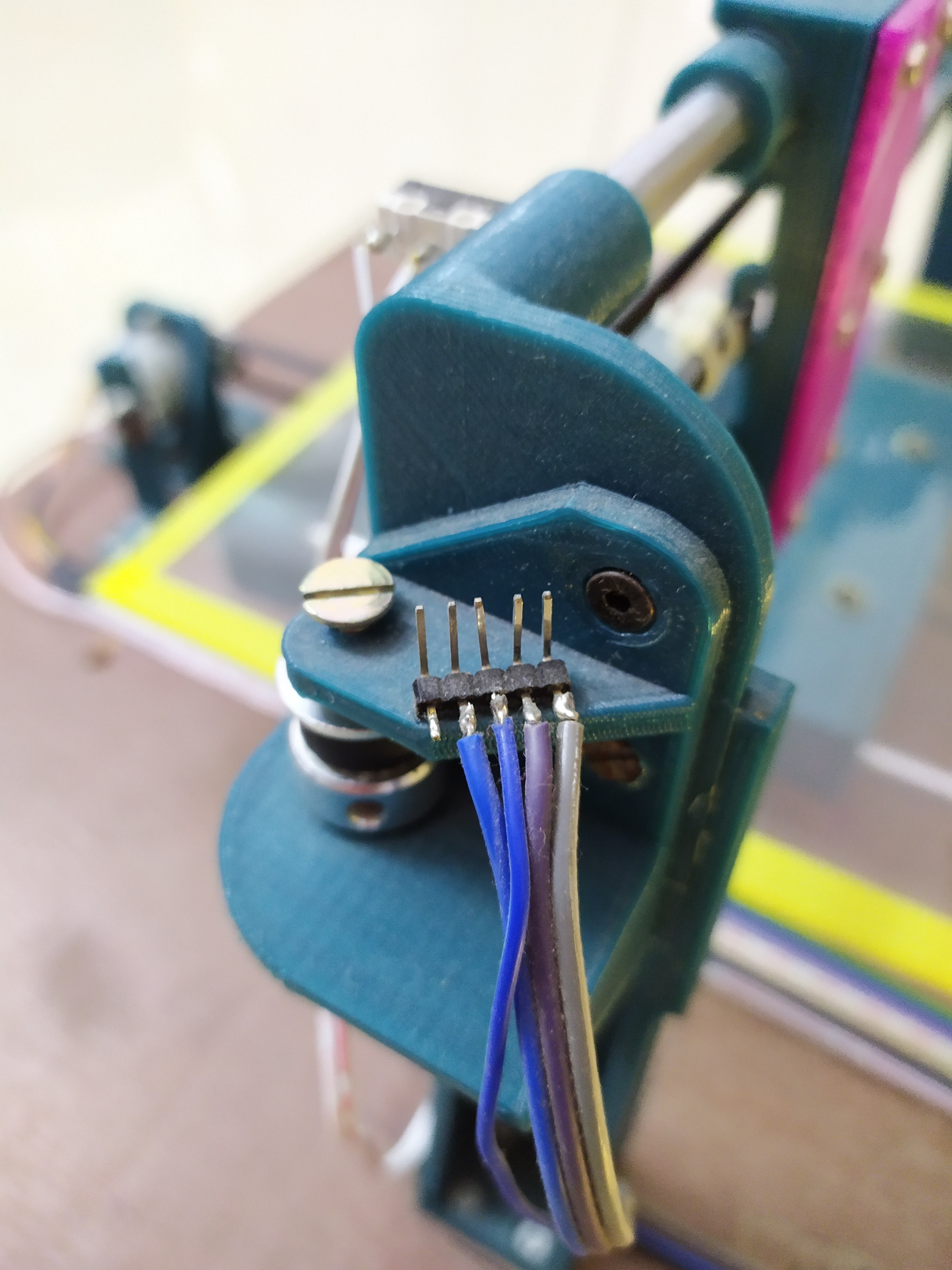
MAGNETIC MOUNT AND THE LASER MODULE
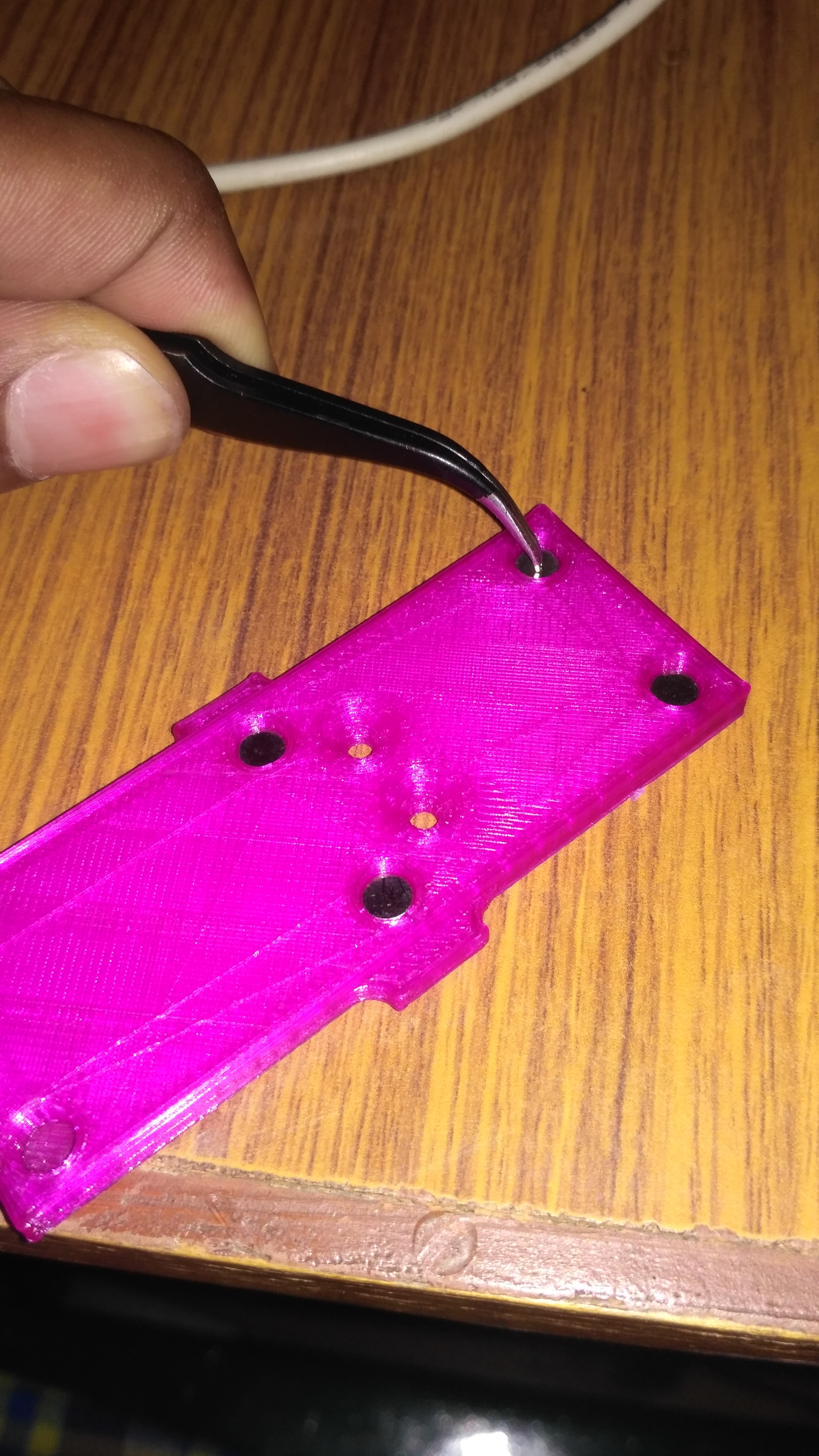
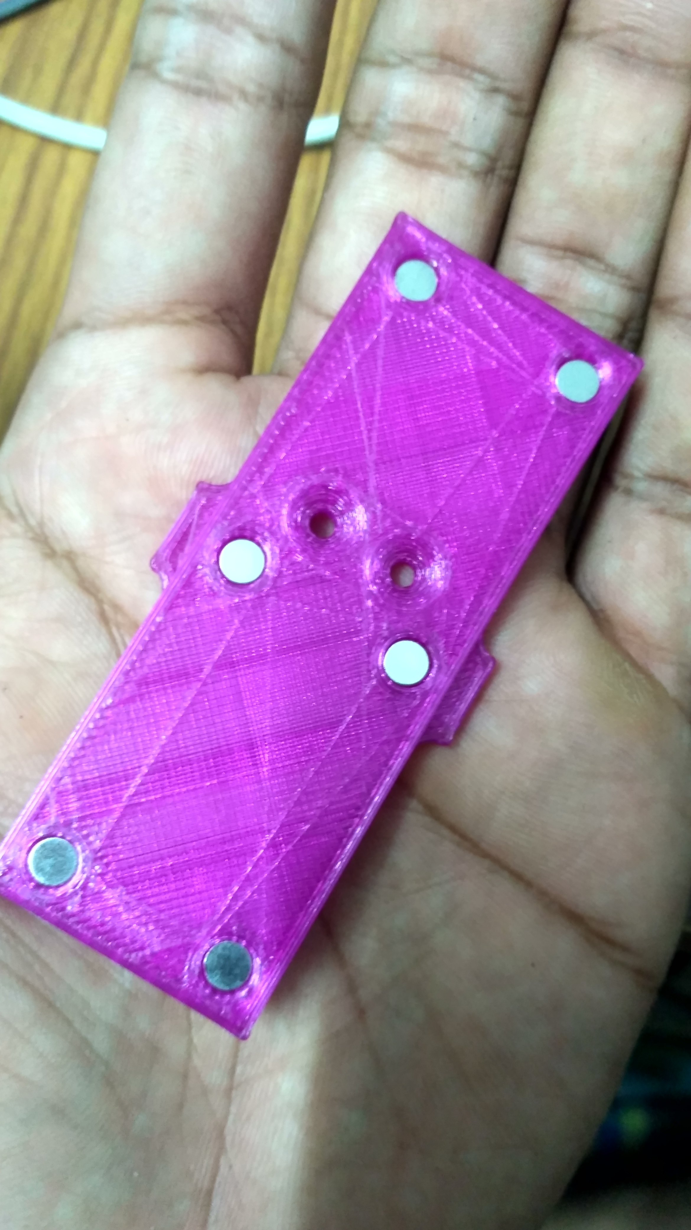
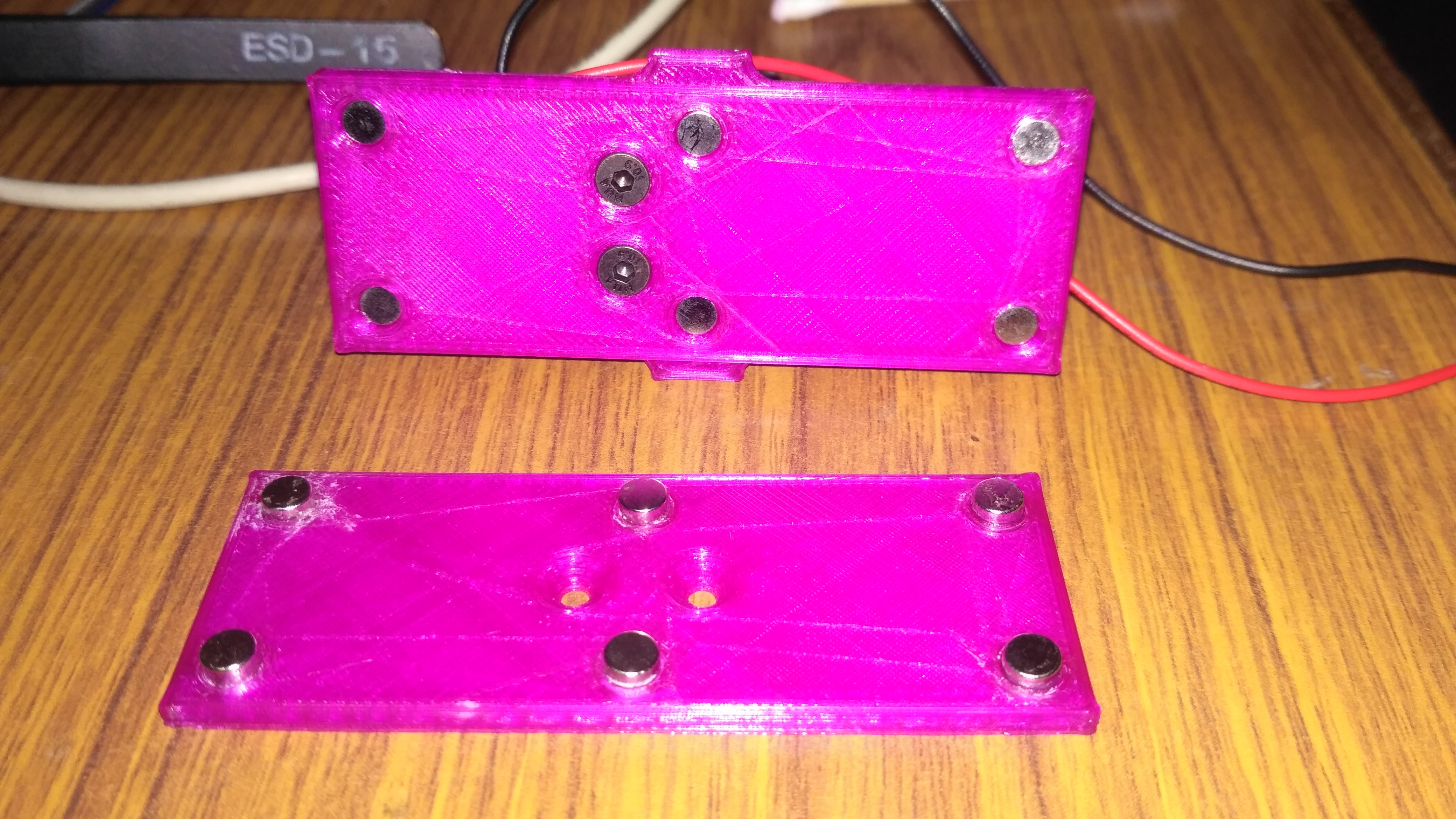
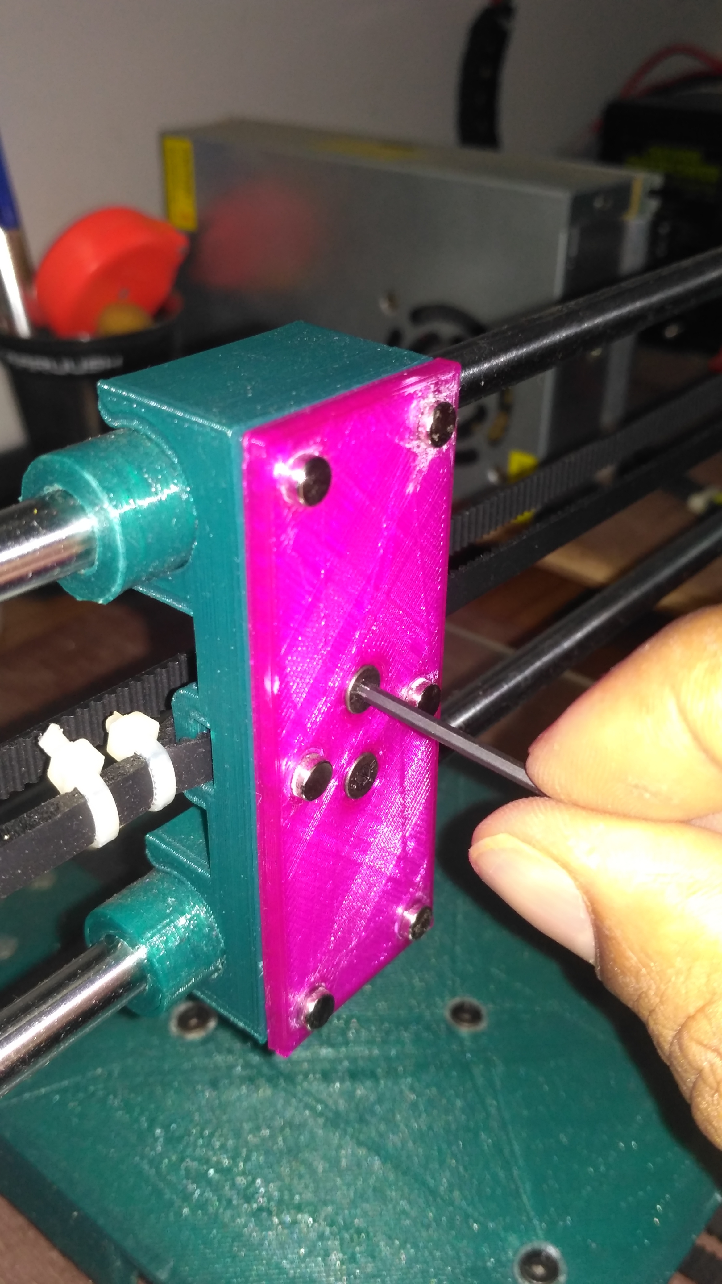
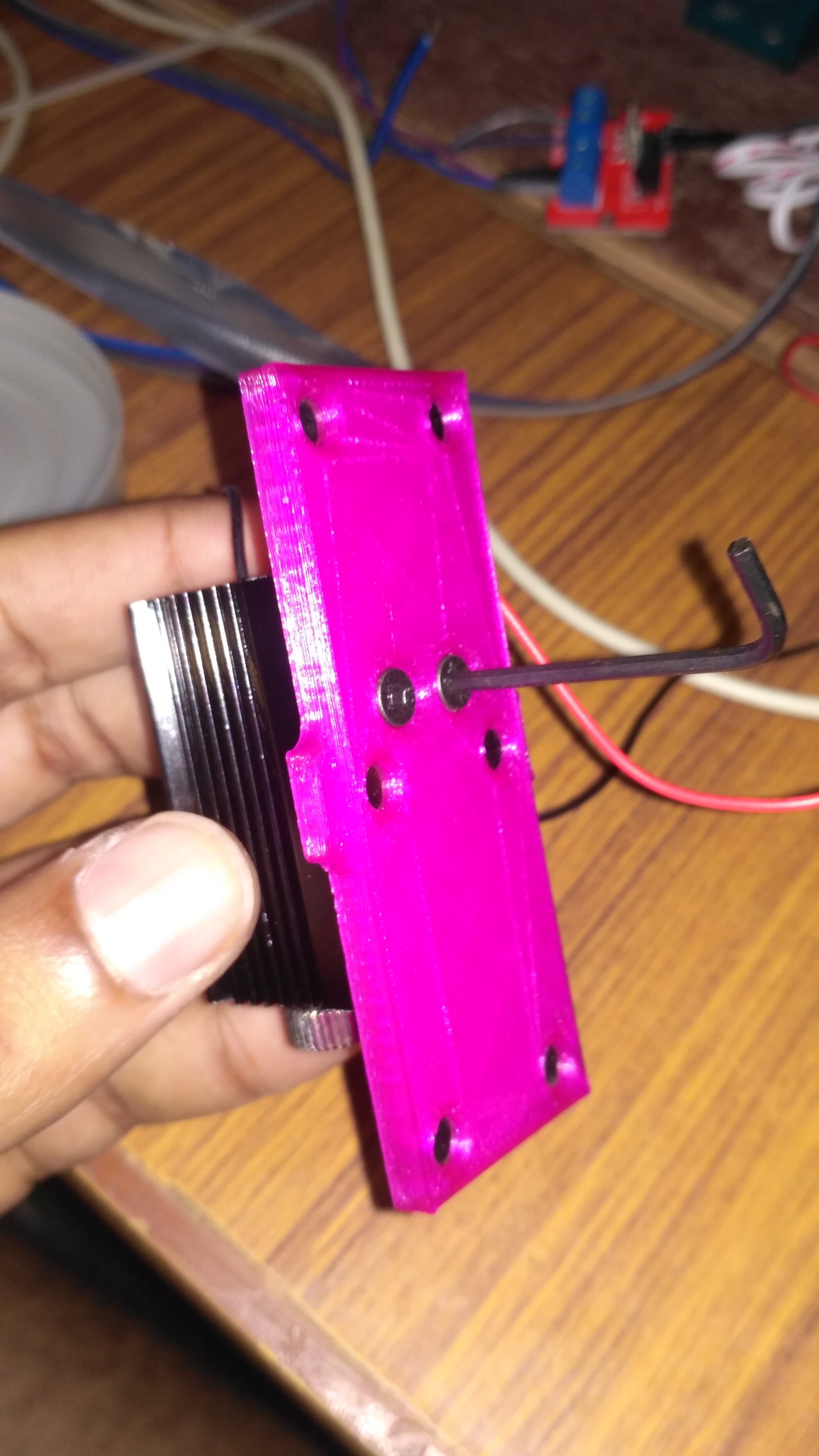
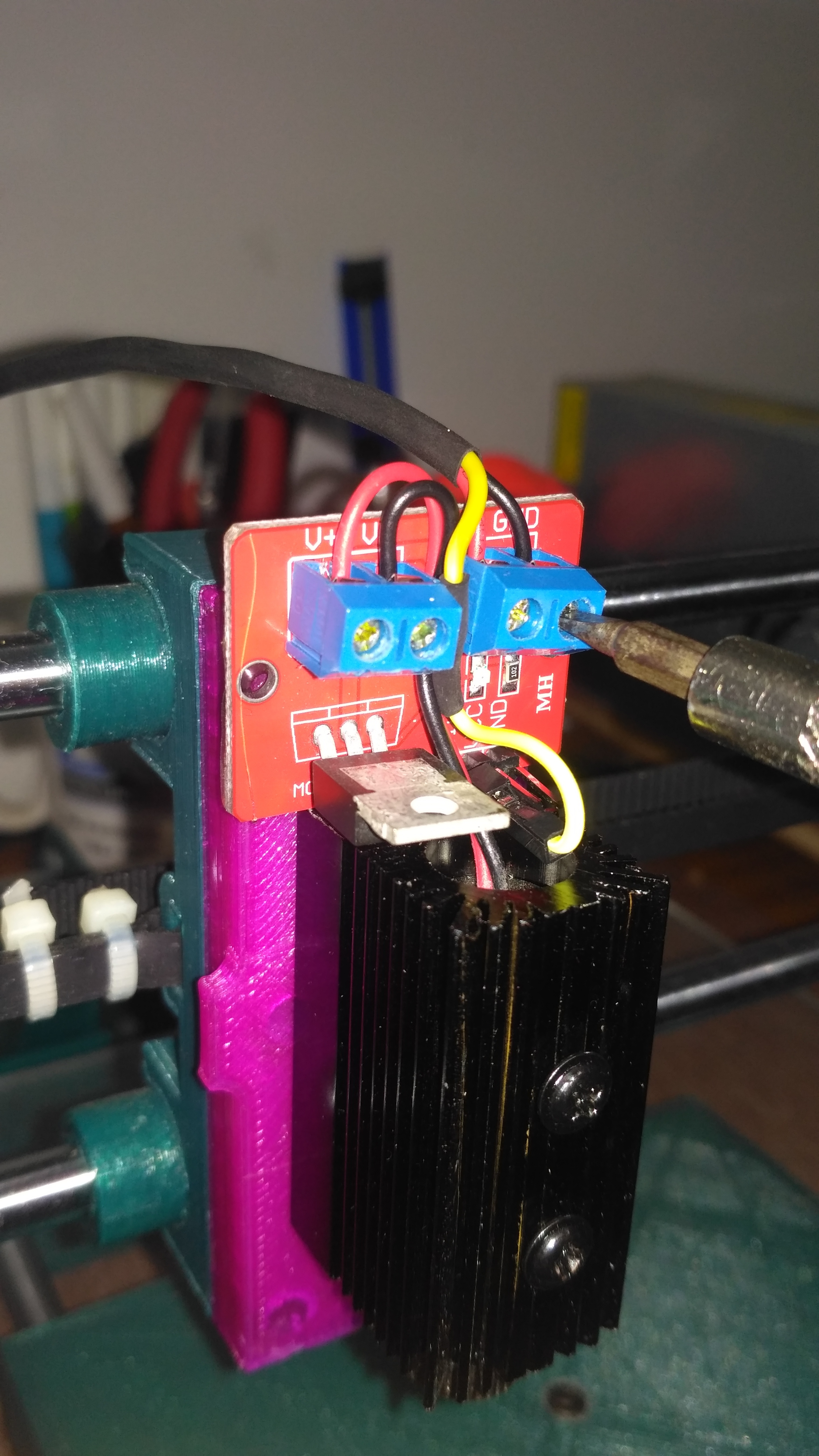
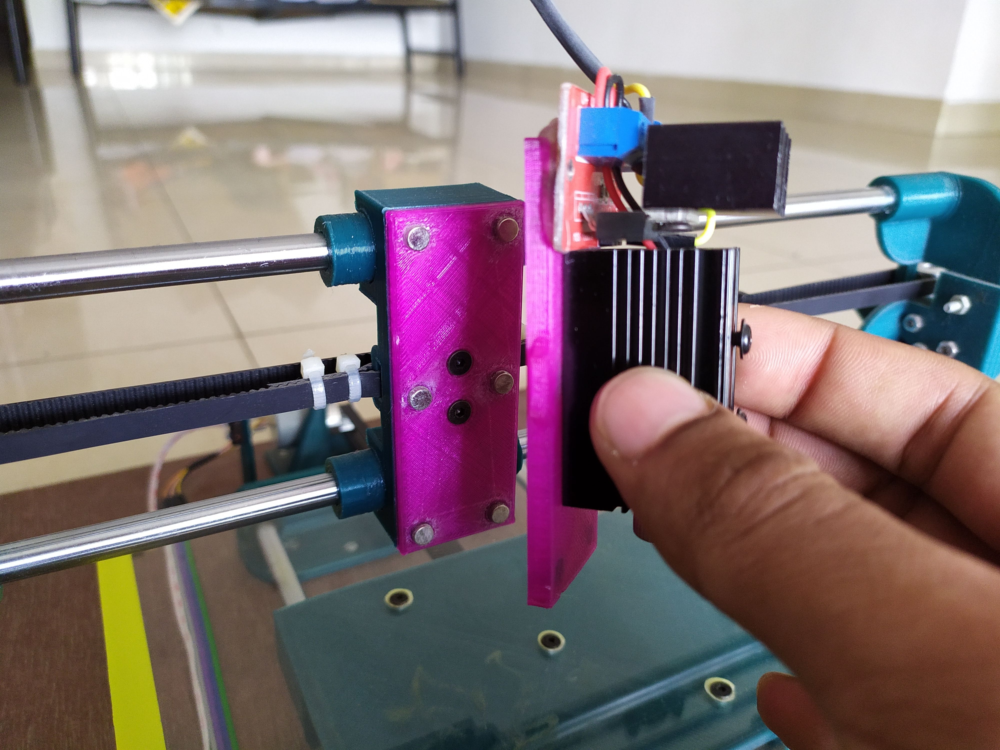
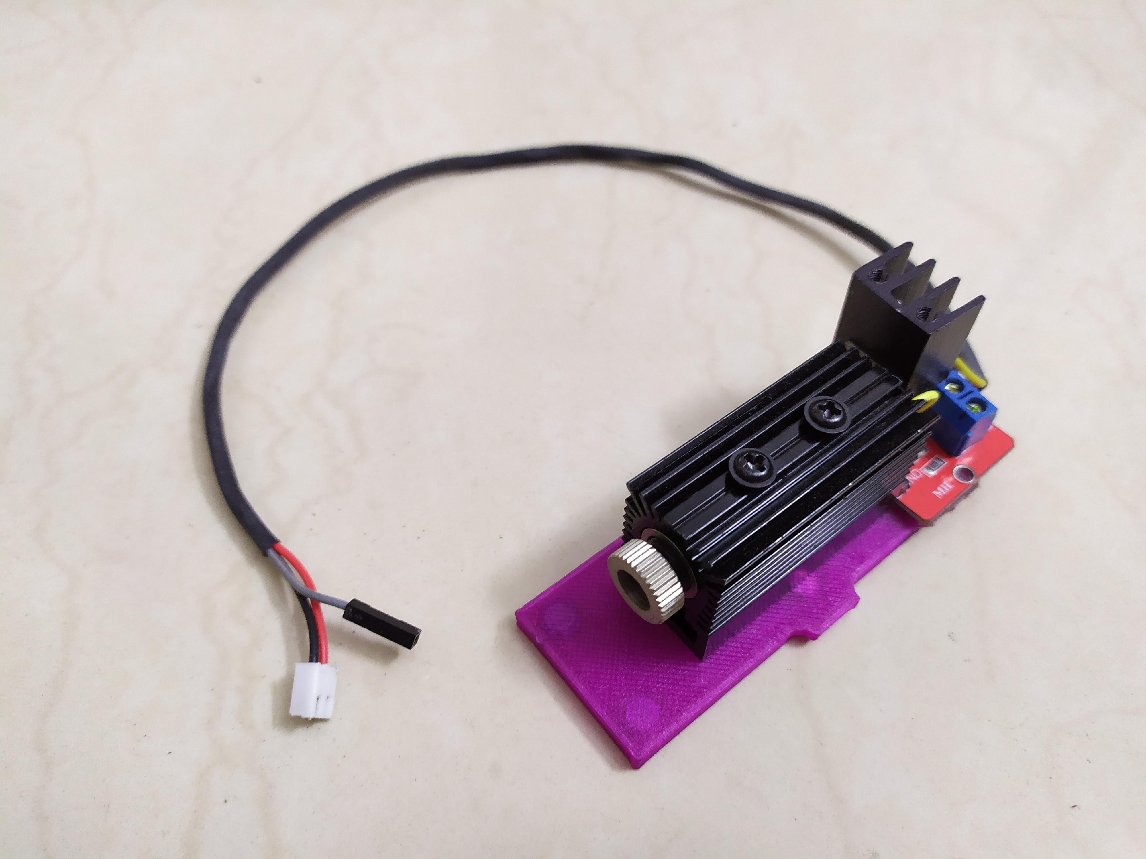
- Once both the mount halves are 3D printed, insert the magnets into the slots with a little bit of superglue in between. Make sure that the same poles are facing outside in one half and the opposite poles are facing outside in the second half of the mount.
- Fasten the half with a long slot in the middle to the X-axis carriage using two M3 12mm bolts and nuts. The long slot is provided to adjust the height of the laser later on if required.
- The remaining half is fastened to the laser module using two M3 12mm bolts.
- The MOSFET module is glued on using hot glue
- A three-wire connector is made. Insulation from the free end is removed and the wires are fastened to the screw terminals of the MOSFET module. The +ve and -ve of the laser are connected to V+and V- respectively of the MOSFET module. The power is connected to the VCC and GND respectively. The signal wire is connected to sig pin of the MOSFET module.
PEN LIFTING MODULE
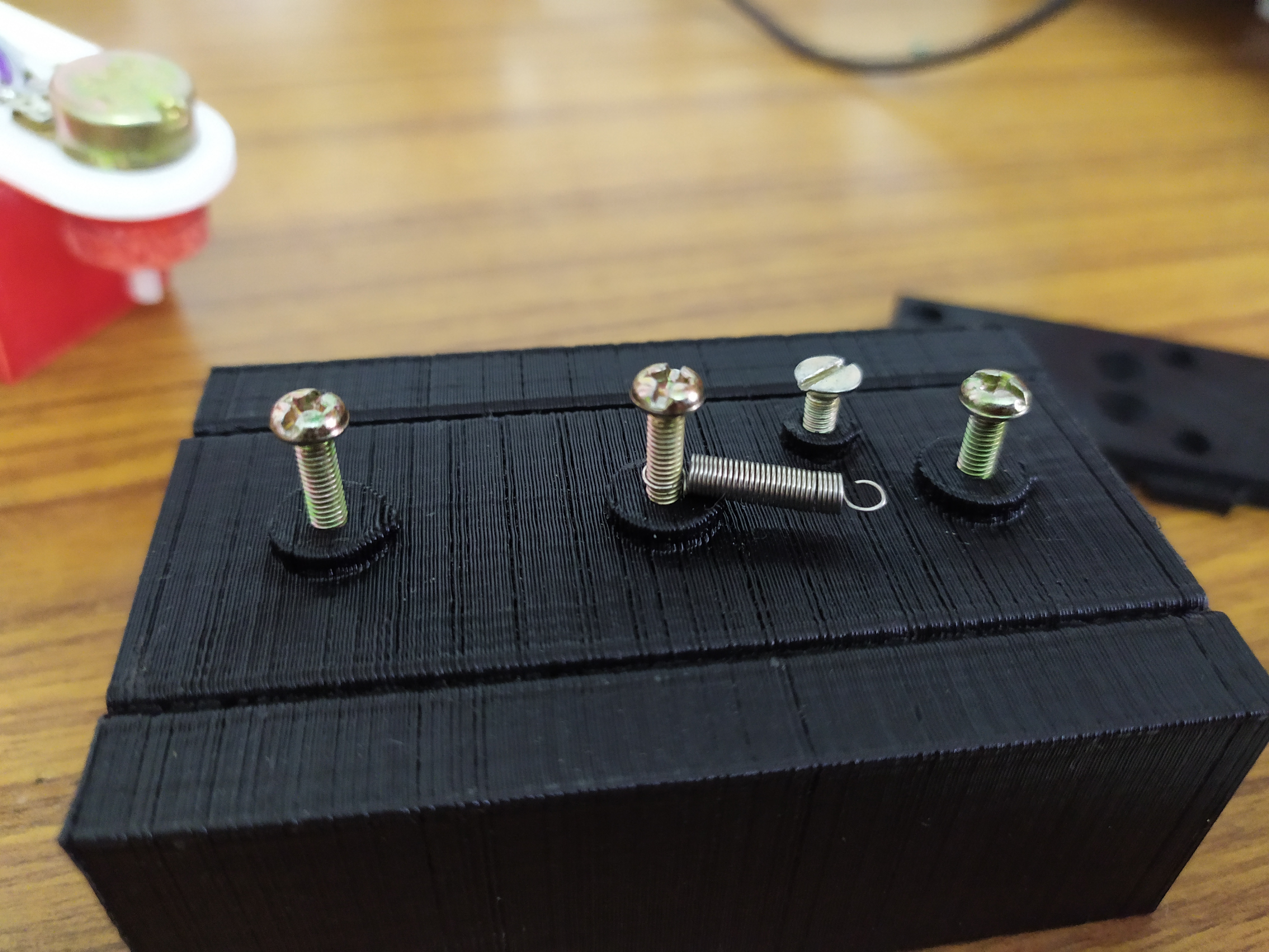
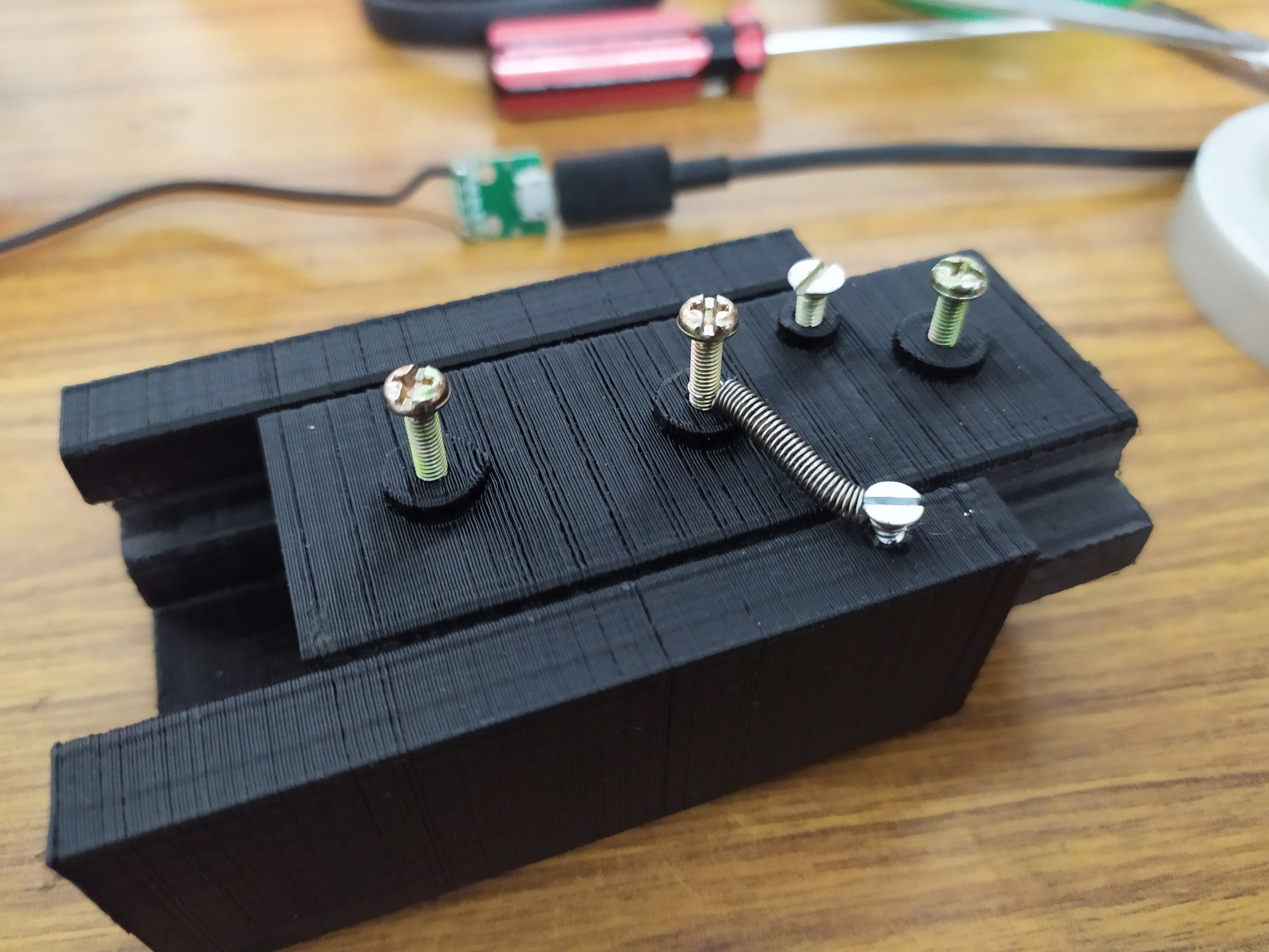
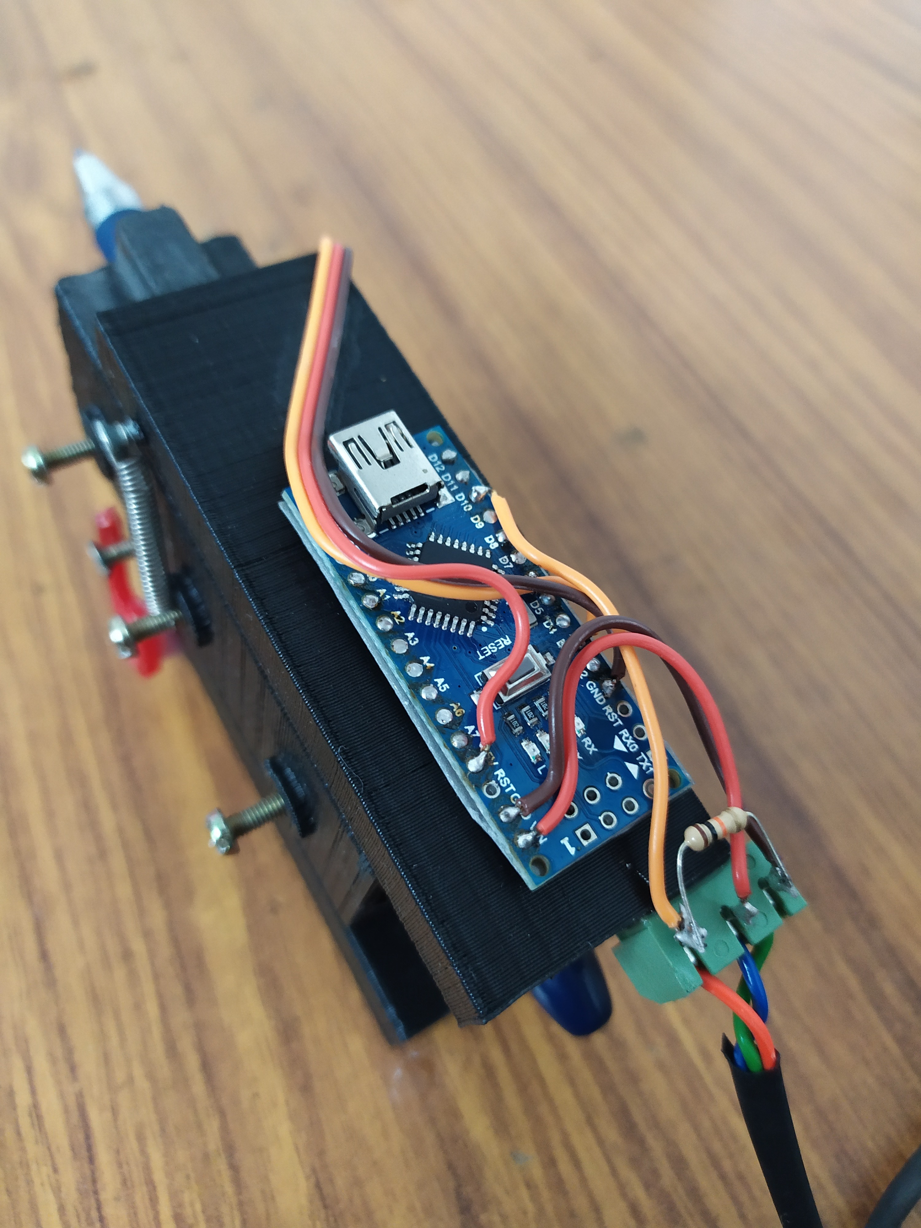


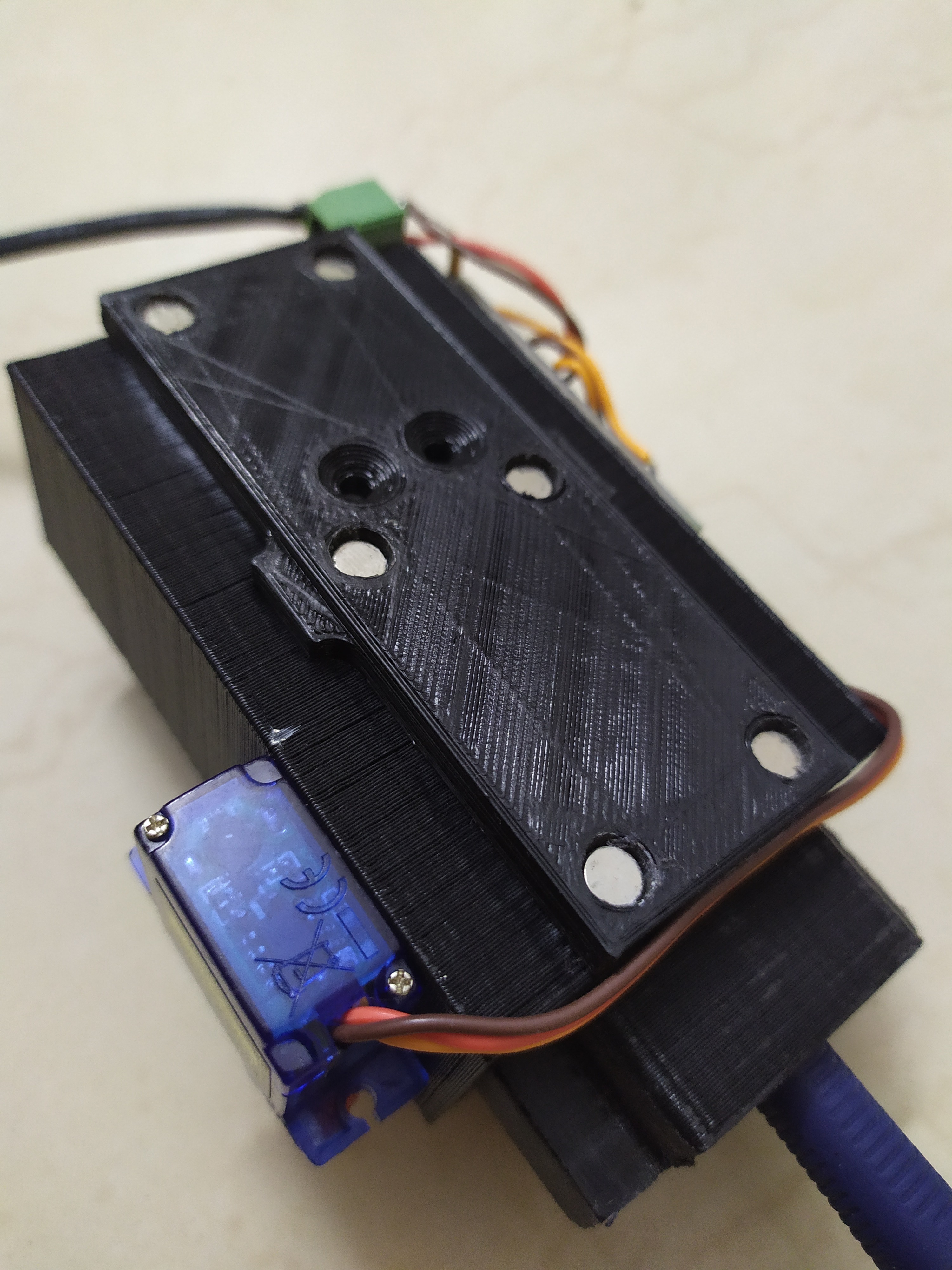
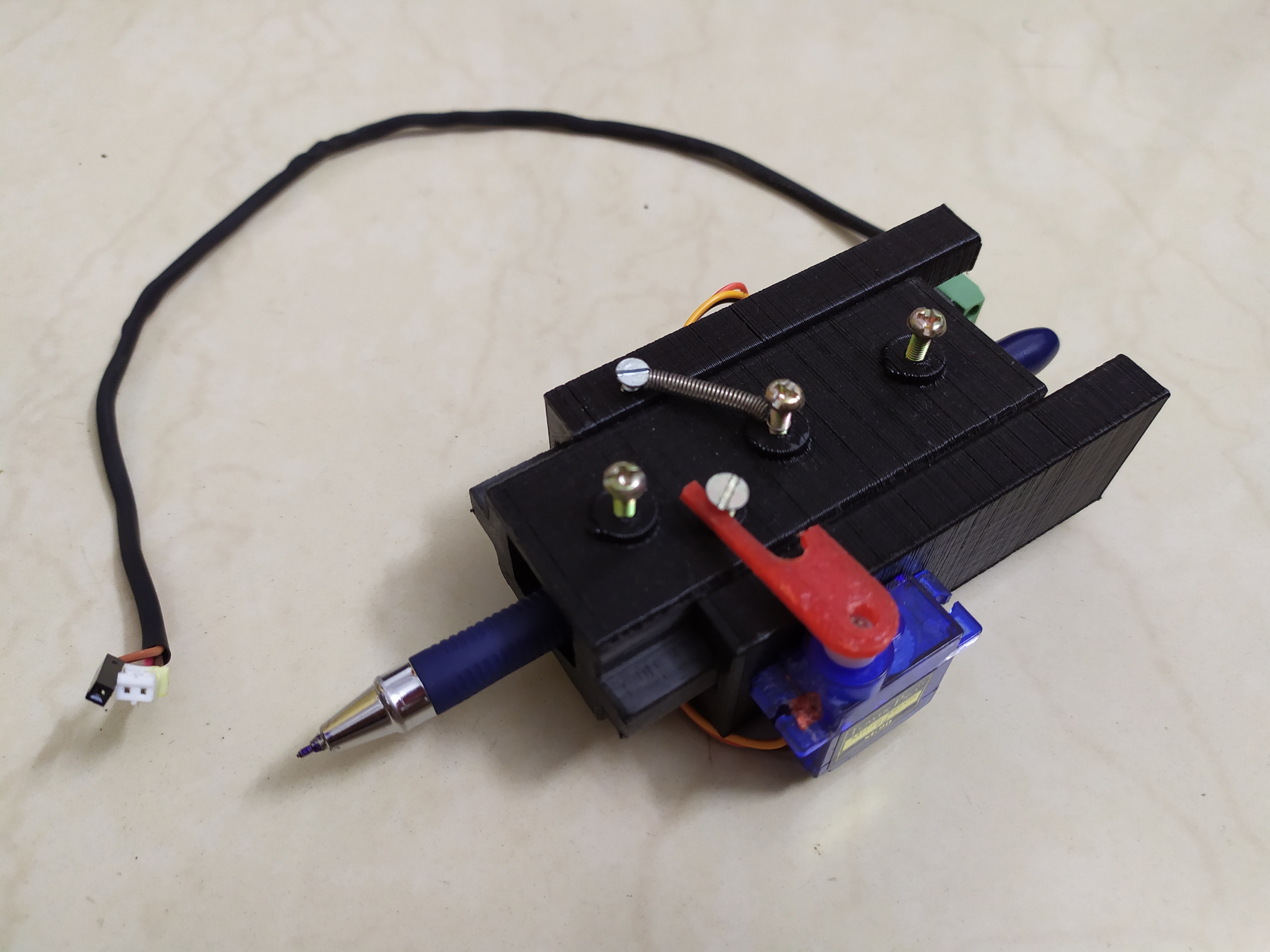
- Once both the pieces are 3D printed, the faces which come in contact with each other ae smoothened using a file and sandpaper until both the pieces slide one inside the other with very little friction.
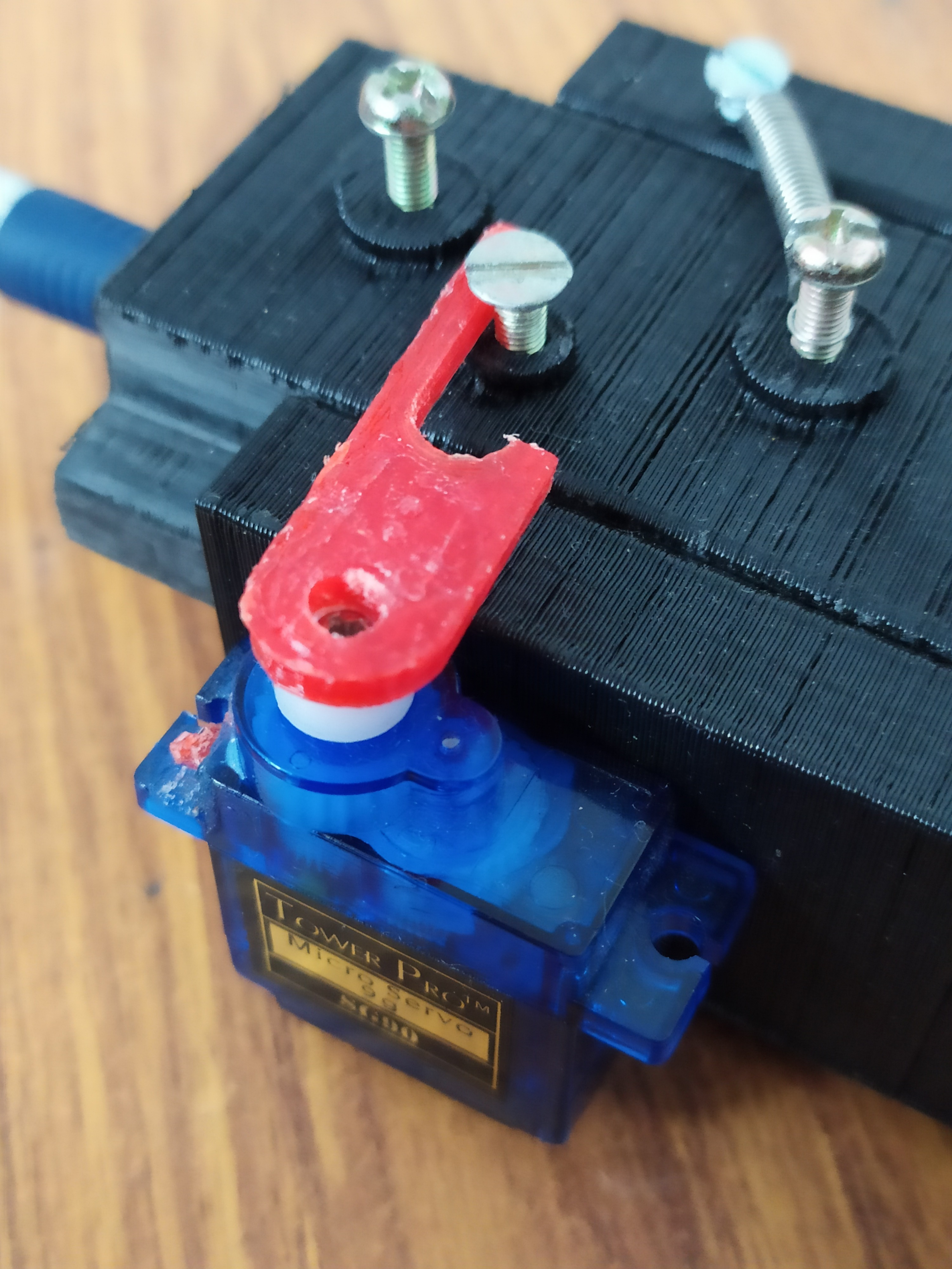
- Now three M3 40mm bolts are screwed in. These bolts are used to hold the pen rigidly inside the setup. A spring is inserted before screwing the middle bolt.
- An M3 12 mm bolt is also screwed into one of the holes for the servo motor to push on.
- A screw is used to hold the free end of the spring in tension so that writing pressure can be applied.
- A servo motor is glued on as seen in the picture.
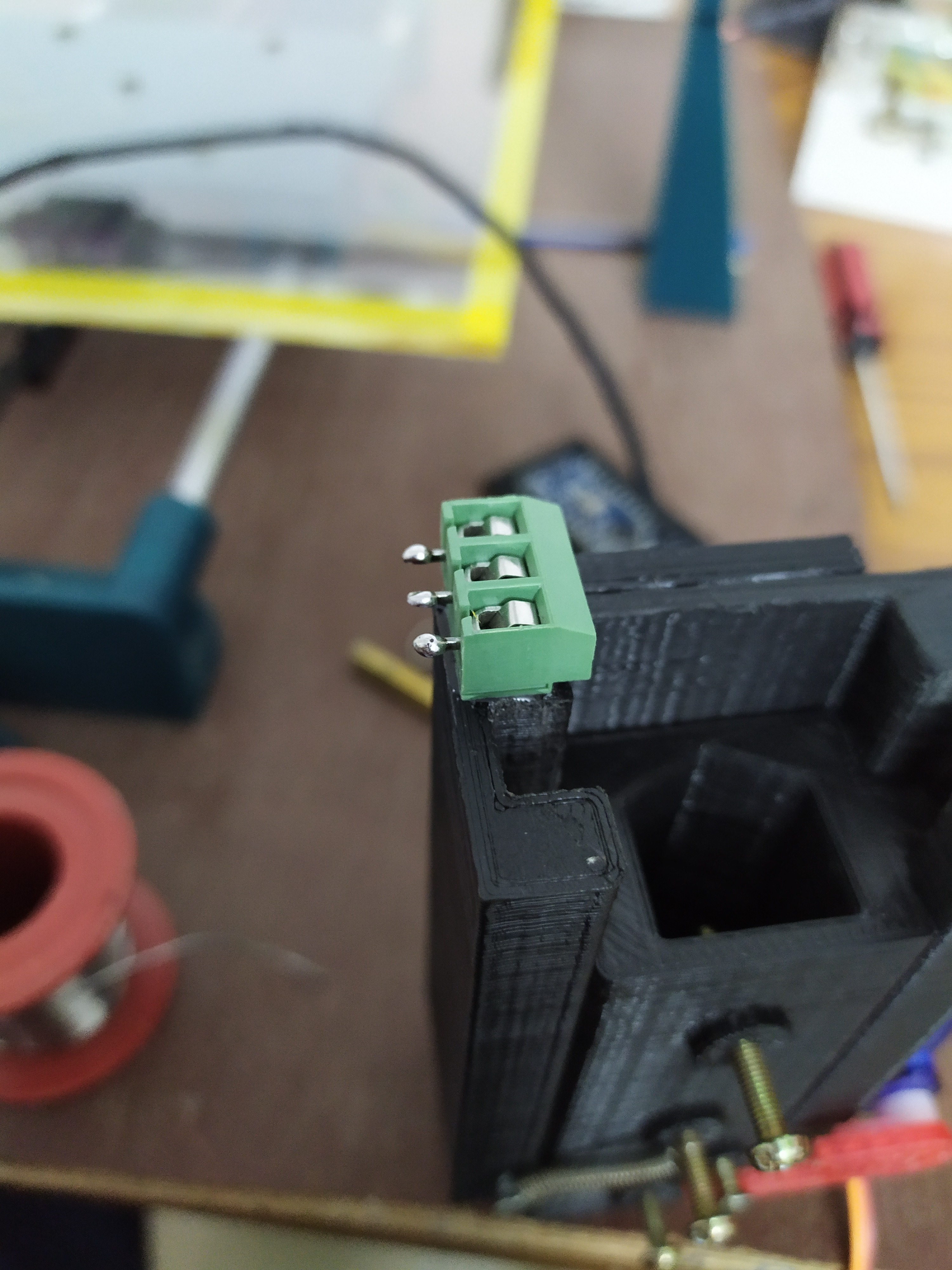
- Wire screw terminals are also glued on using superglue.
- An Arduino nano is used here to convert the laser control signals received from the CNC shield into PWM signals which can control the micro servo motor.
WIRING :
- +5 Volt - Vin
- -5 Volt - GND
- Signal - D10
- Servo power +ve - 5V
- Servo power -ve - GND
- Servo signal - D3
Once the wiring is done upload the code file "pen_module_code" attached in this step into your Arduino nano.
Downloads
CIRCUIT DIAGRAM
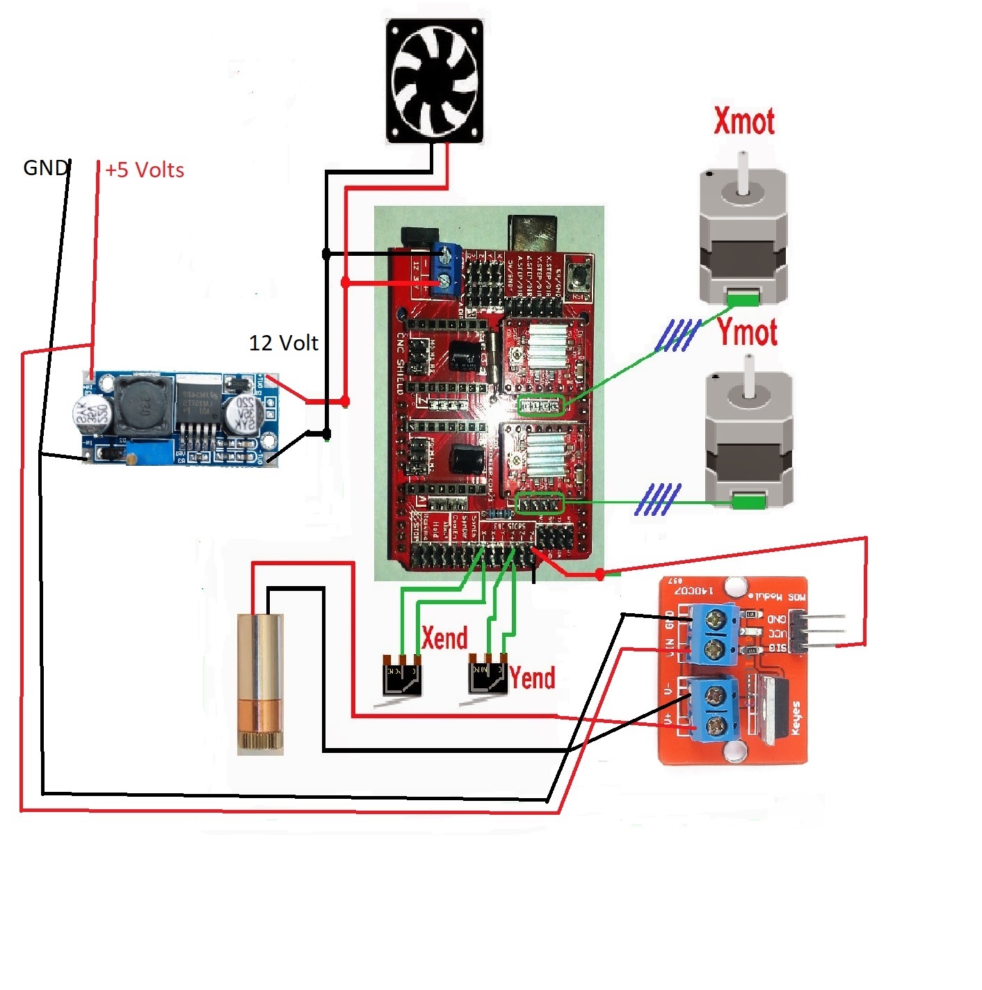
The connection is straight forward
The X and Y motors are plugged into ports marked as X-axis and Y-axis respectively.
The PWM laser signal is taken from the "Z+" pin on the CNC shield.
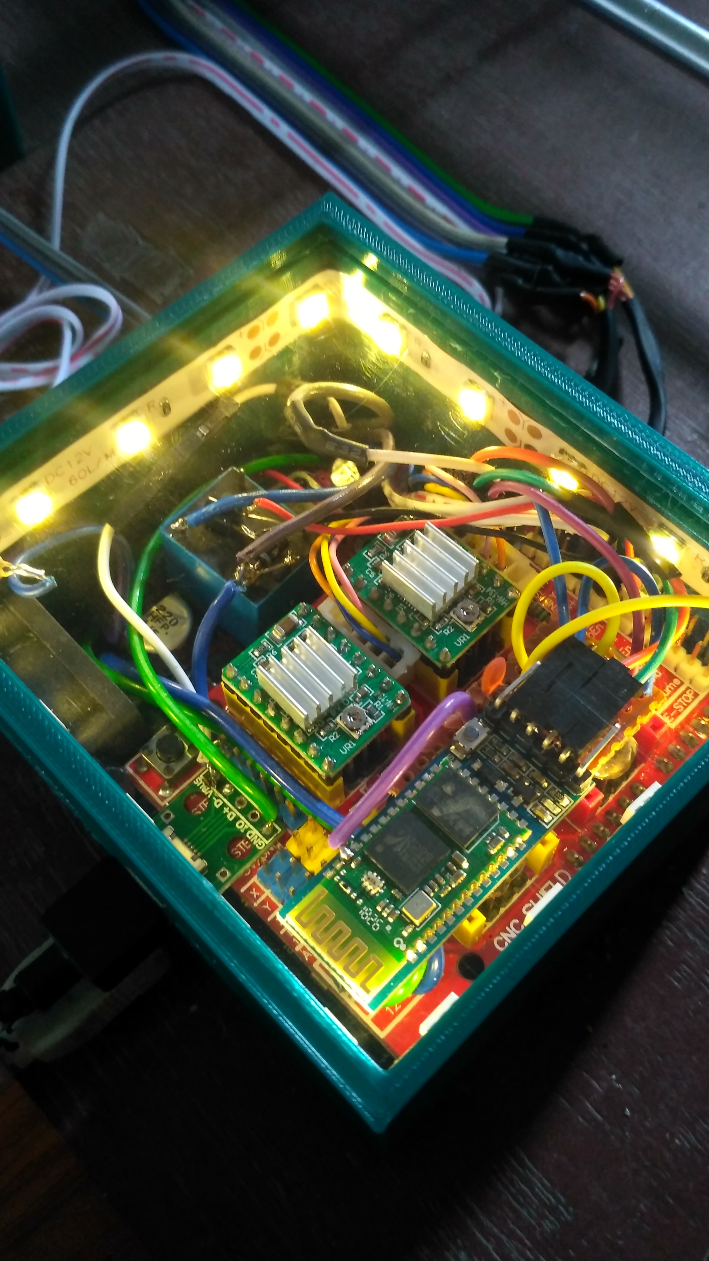
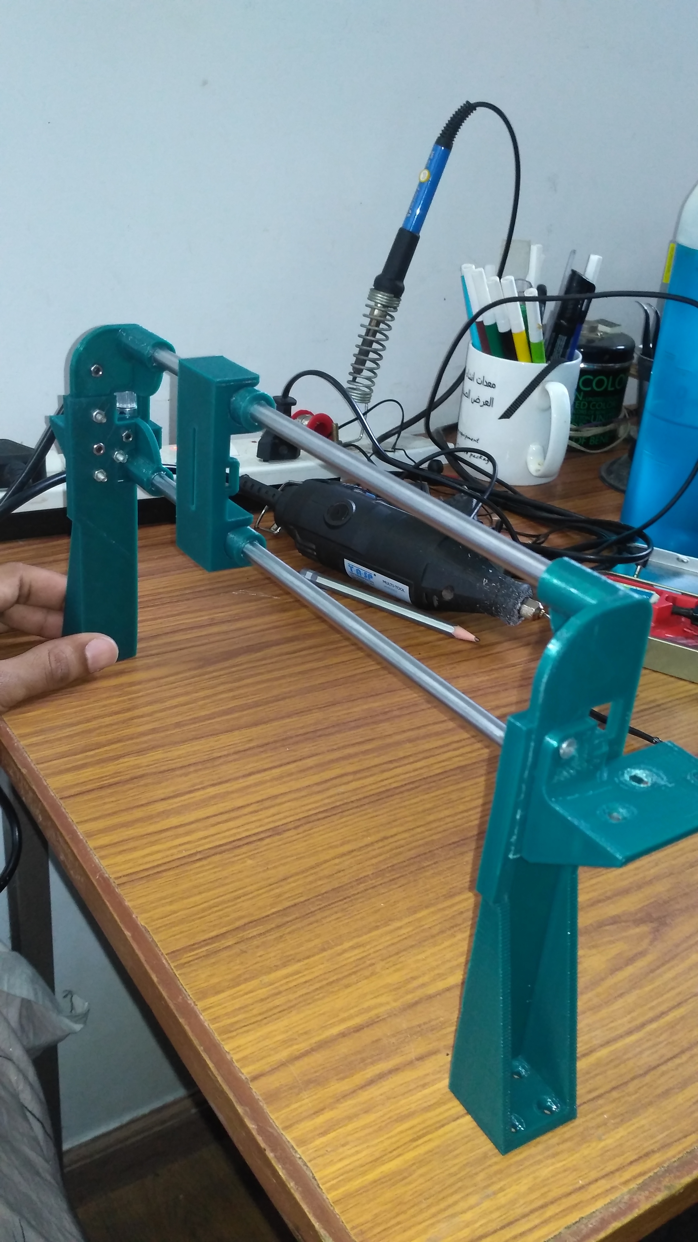
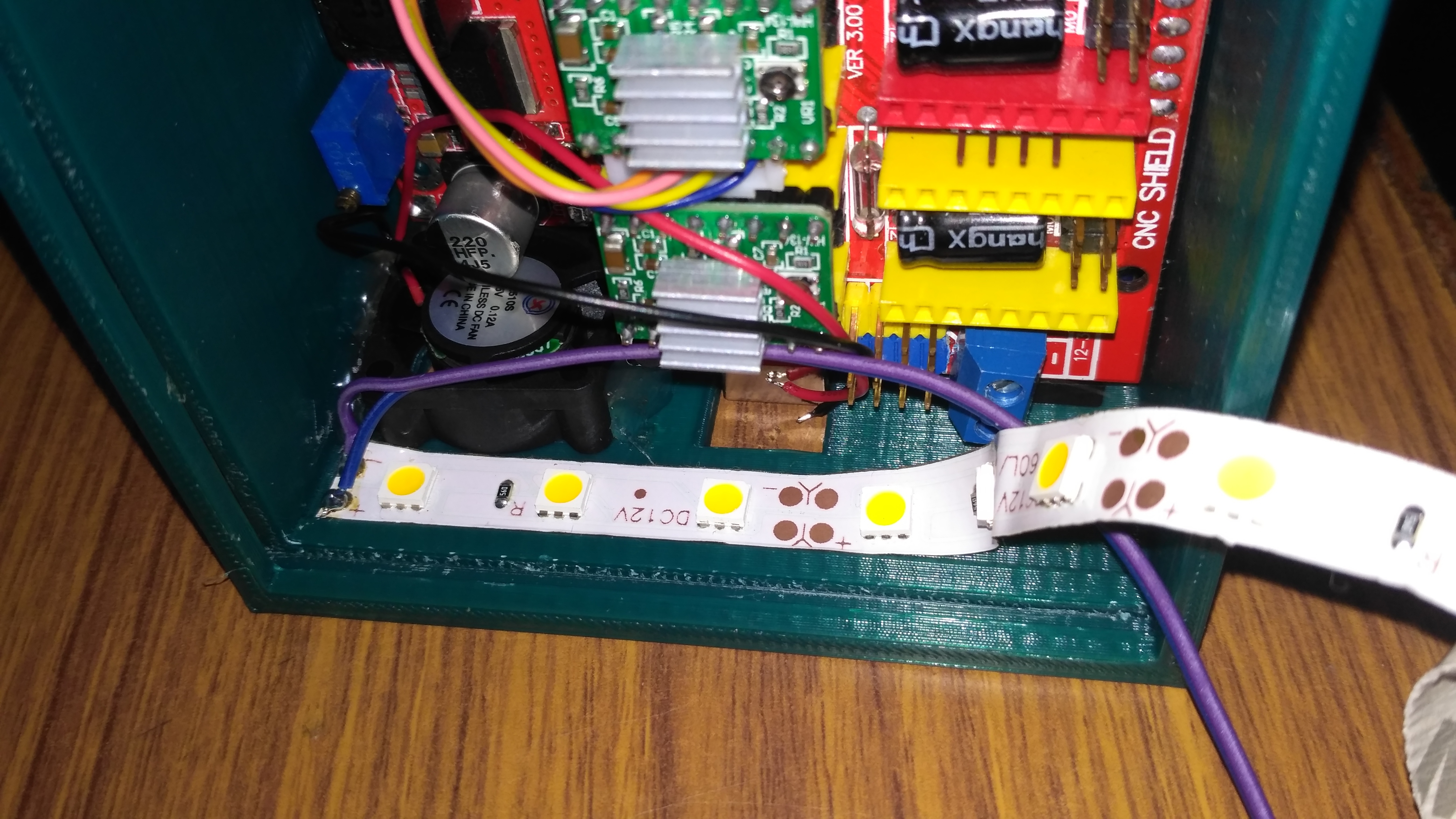
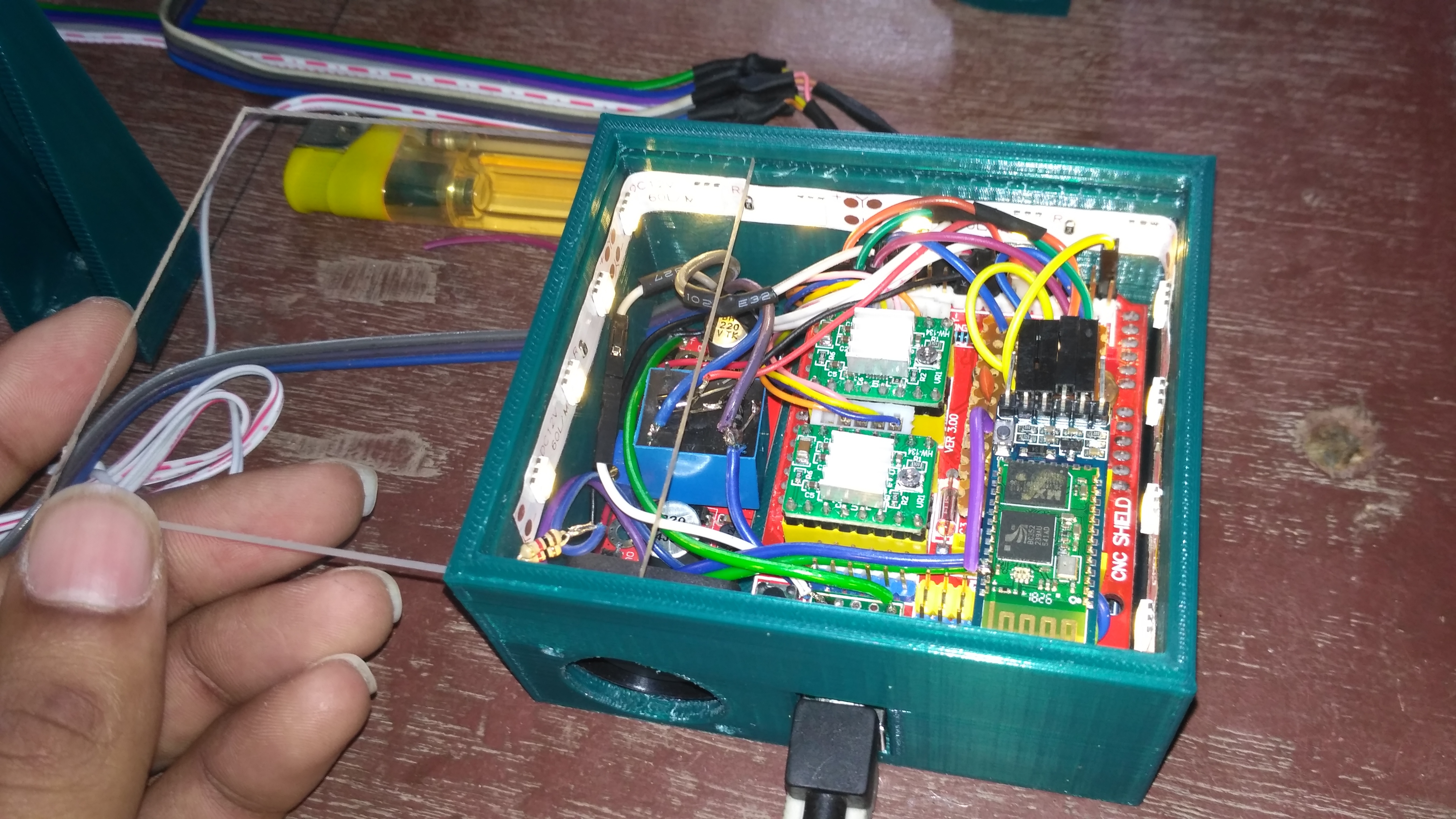
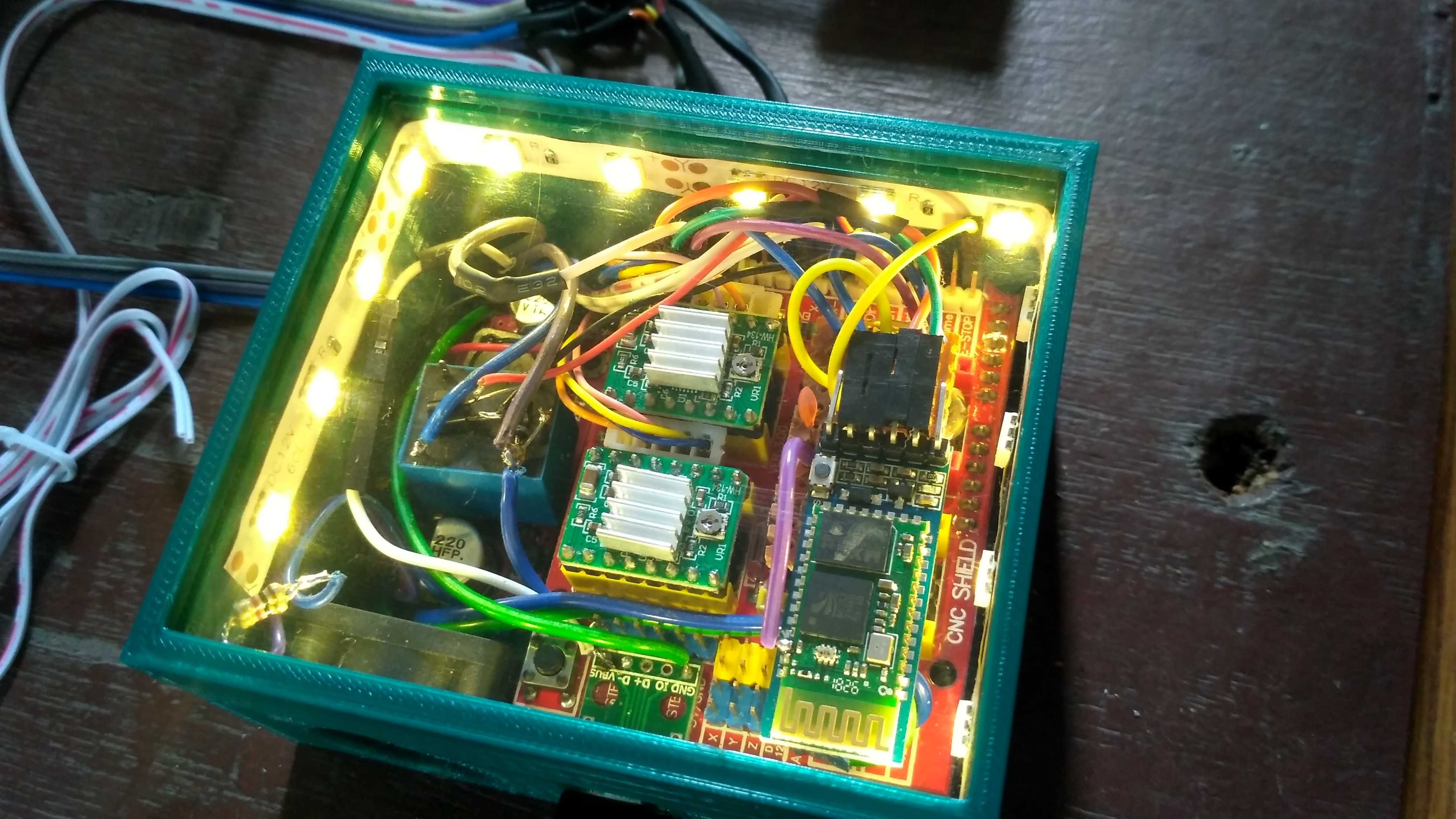
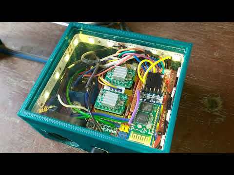
WIRING THE SYSTEM
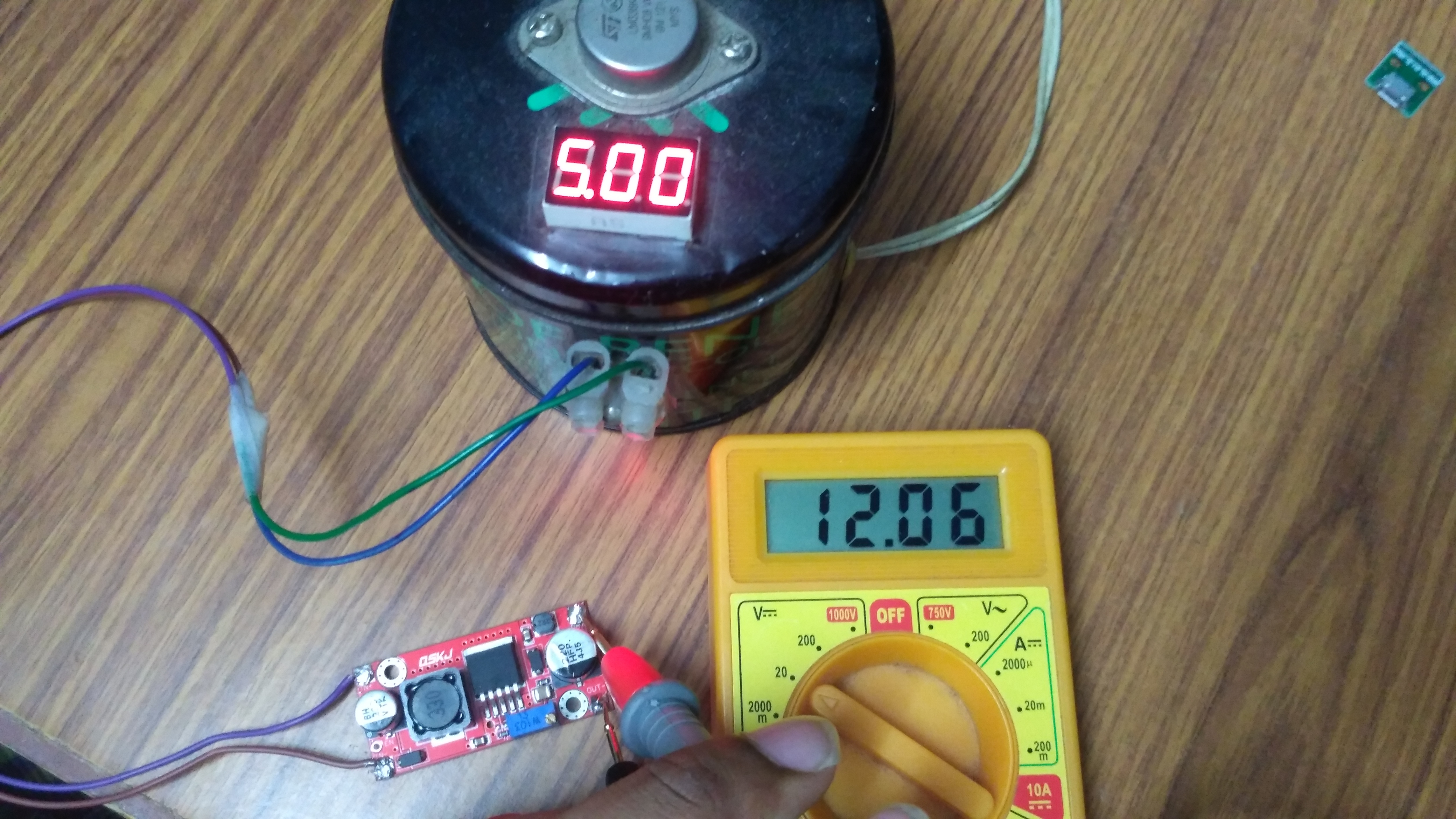
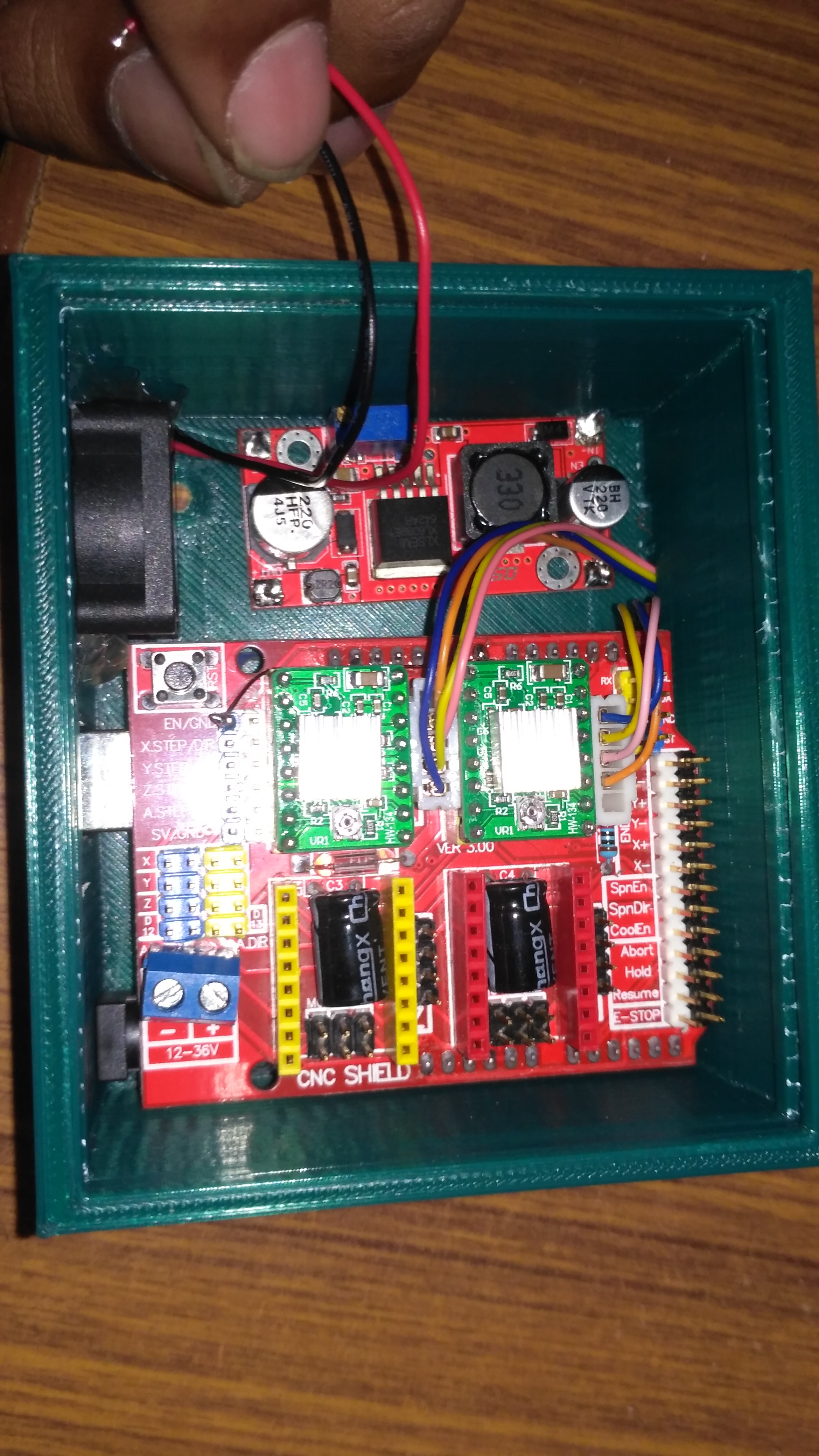
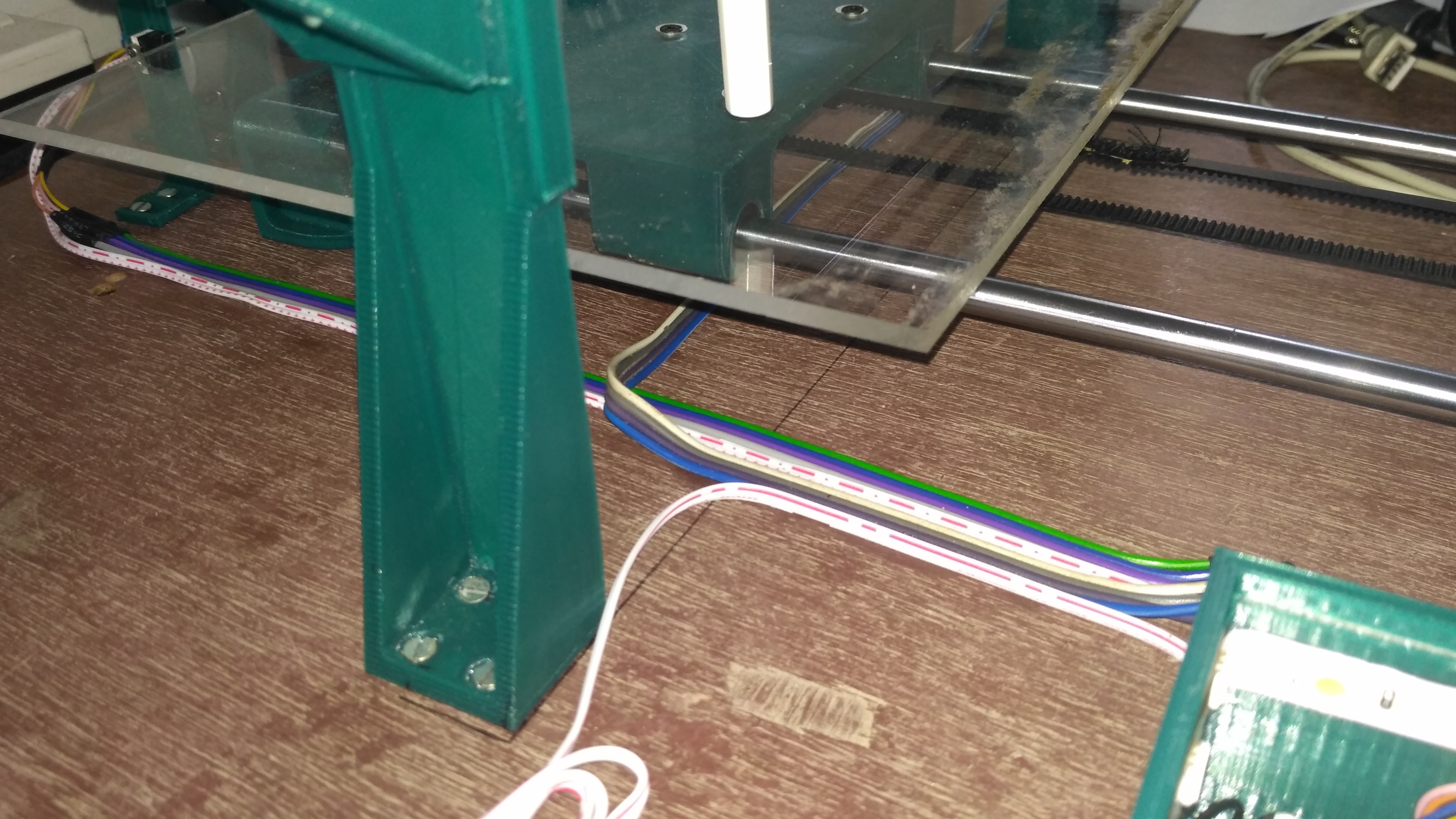
- The boost converter is set to 12 volts by turning the pot on it clockwise.
- The CNC shield is inserted into the Arduino
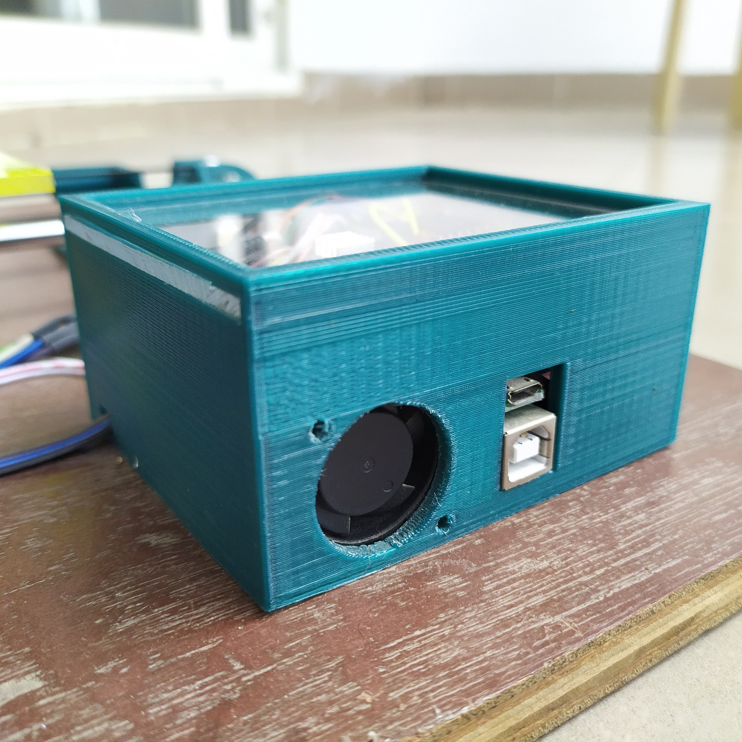
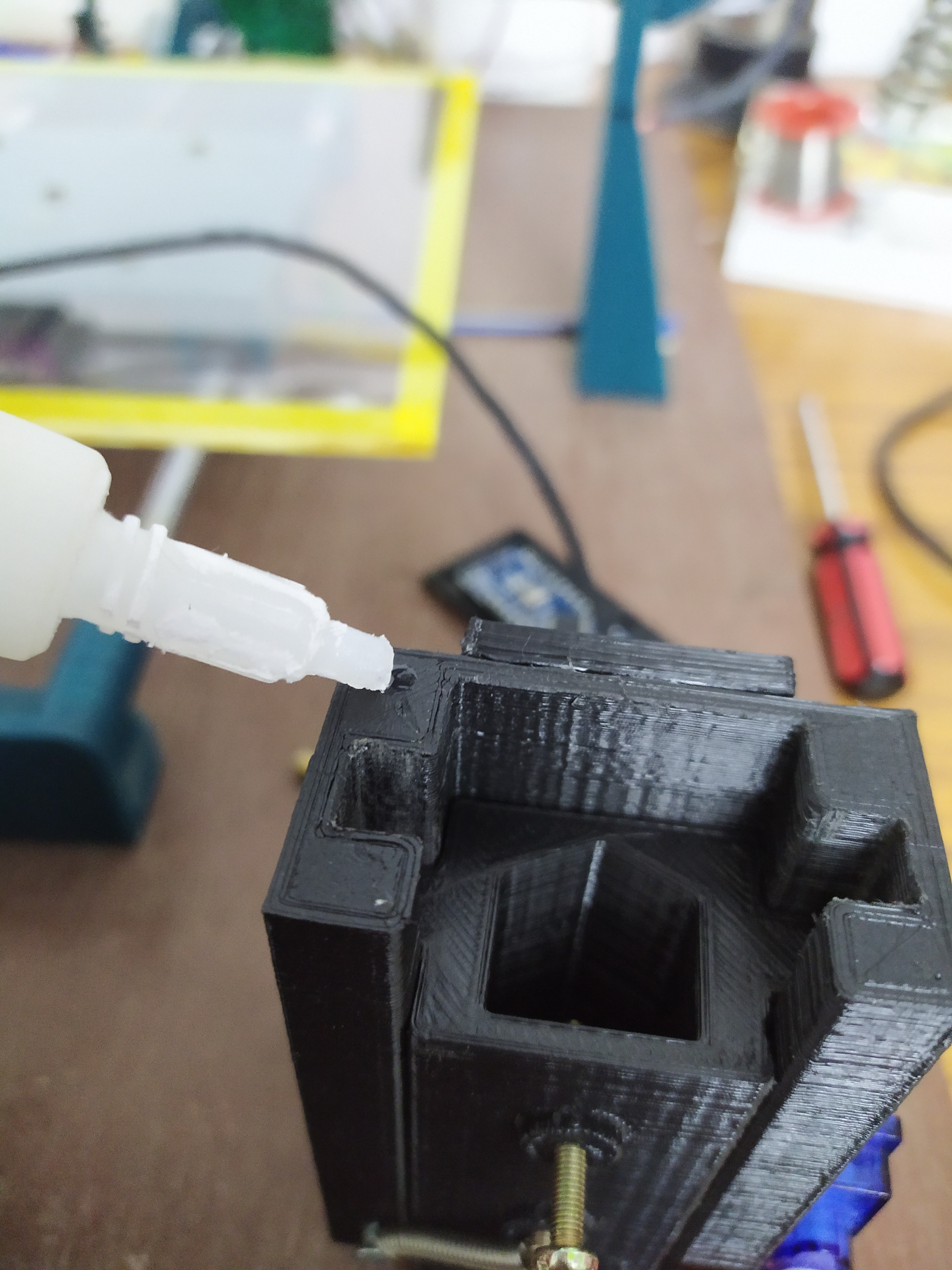
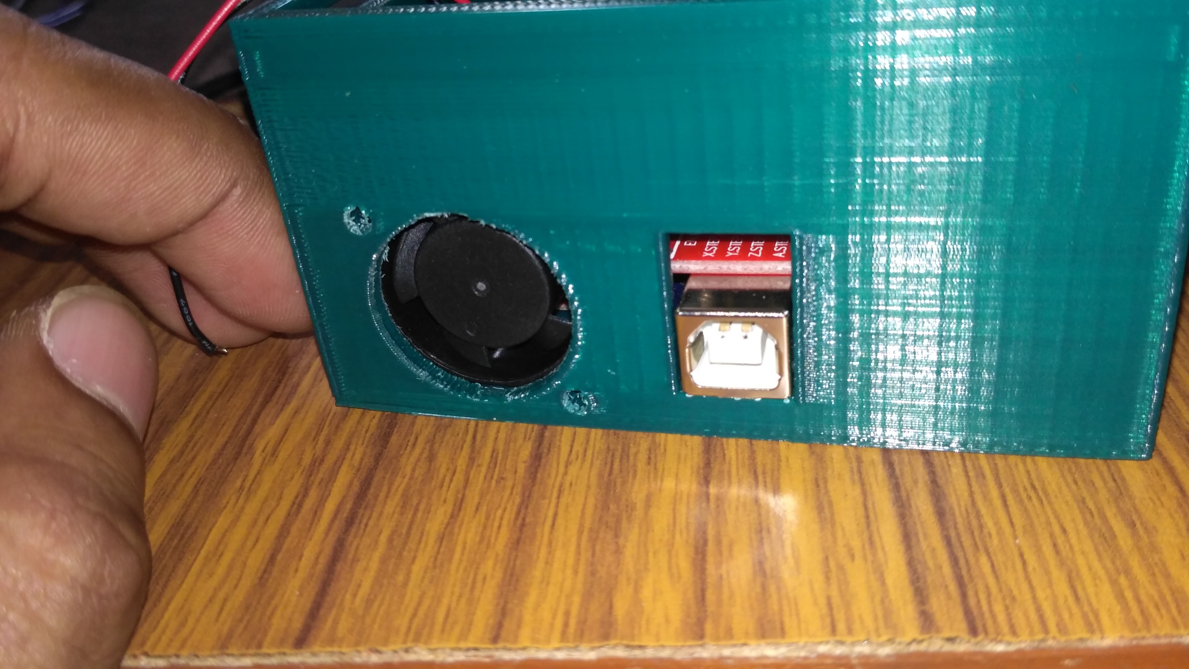
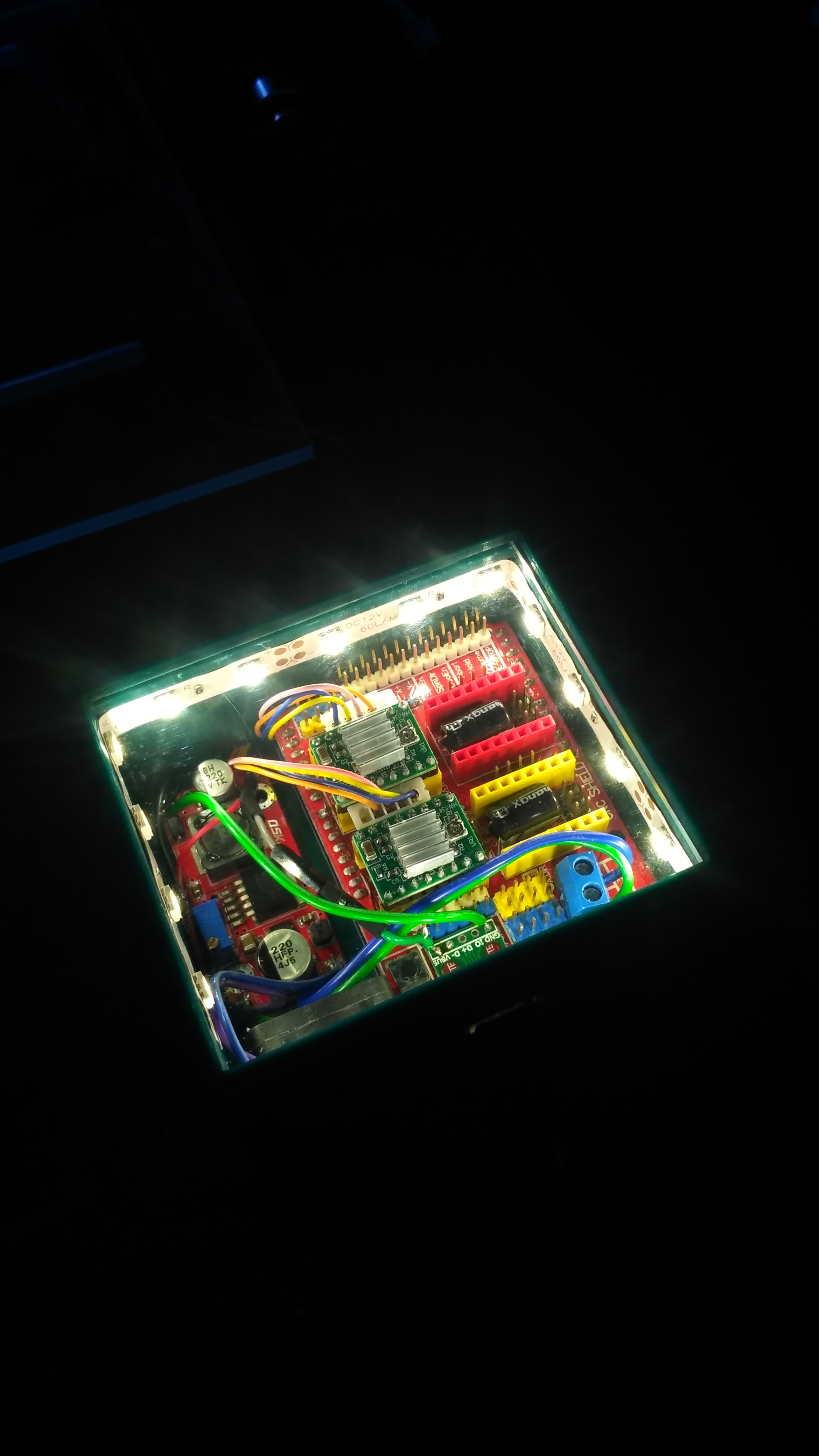
- The cooling fan is glued at the opening provided for it using hot glue. The Arduino along with the CNC shield and the boost module is fixed in the casing
- The LED strip is added for looks as well as for power indication.
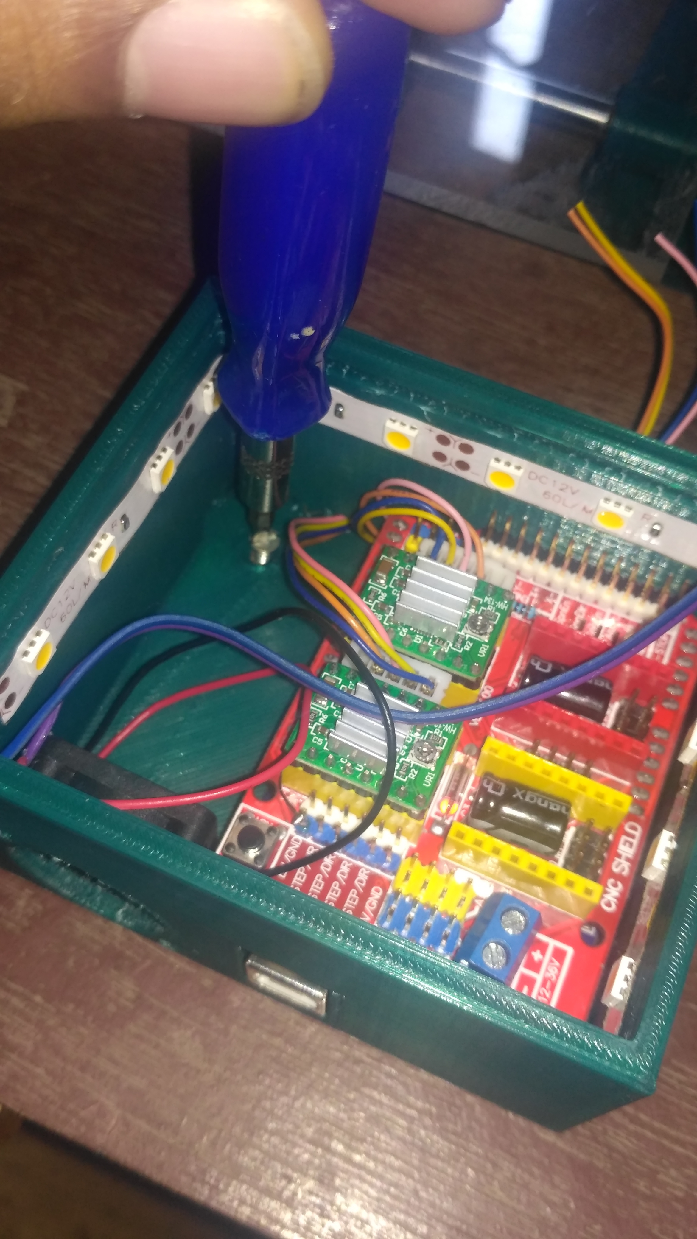
- The 3D printed casing is screwed to the plywood.
- An 87 X 75 mm sheet of transparent acrylic with a thickness of 2 mm is used as the casing cover. It can be slide in through a slot provided for it on one of the sides of the casing.
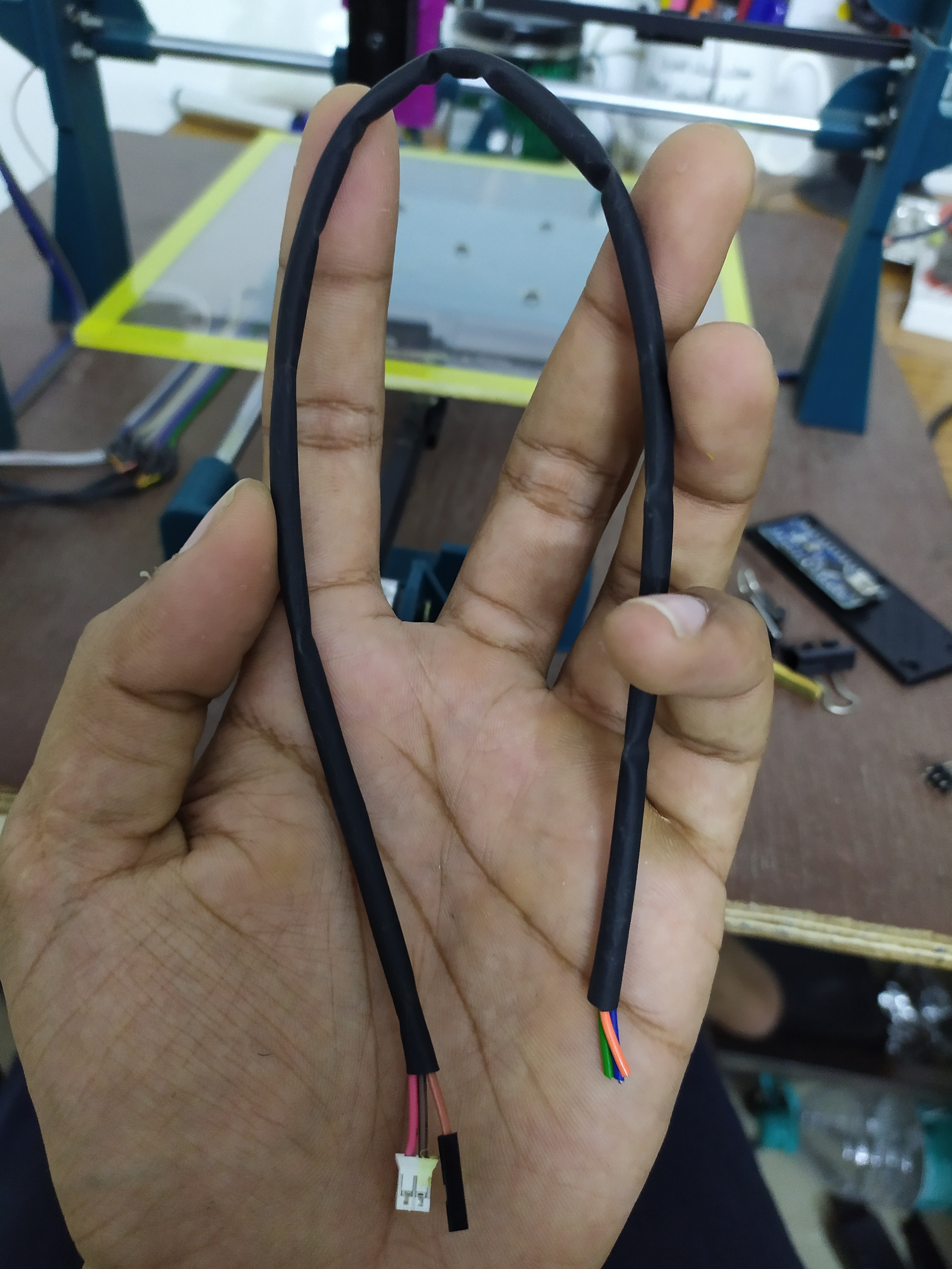
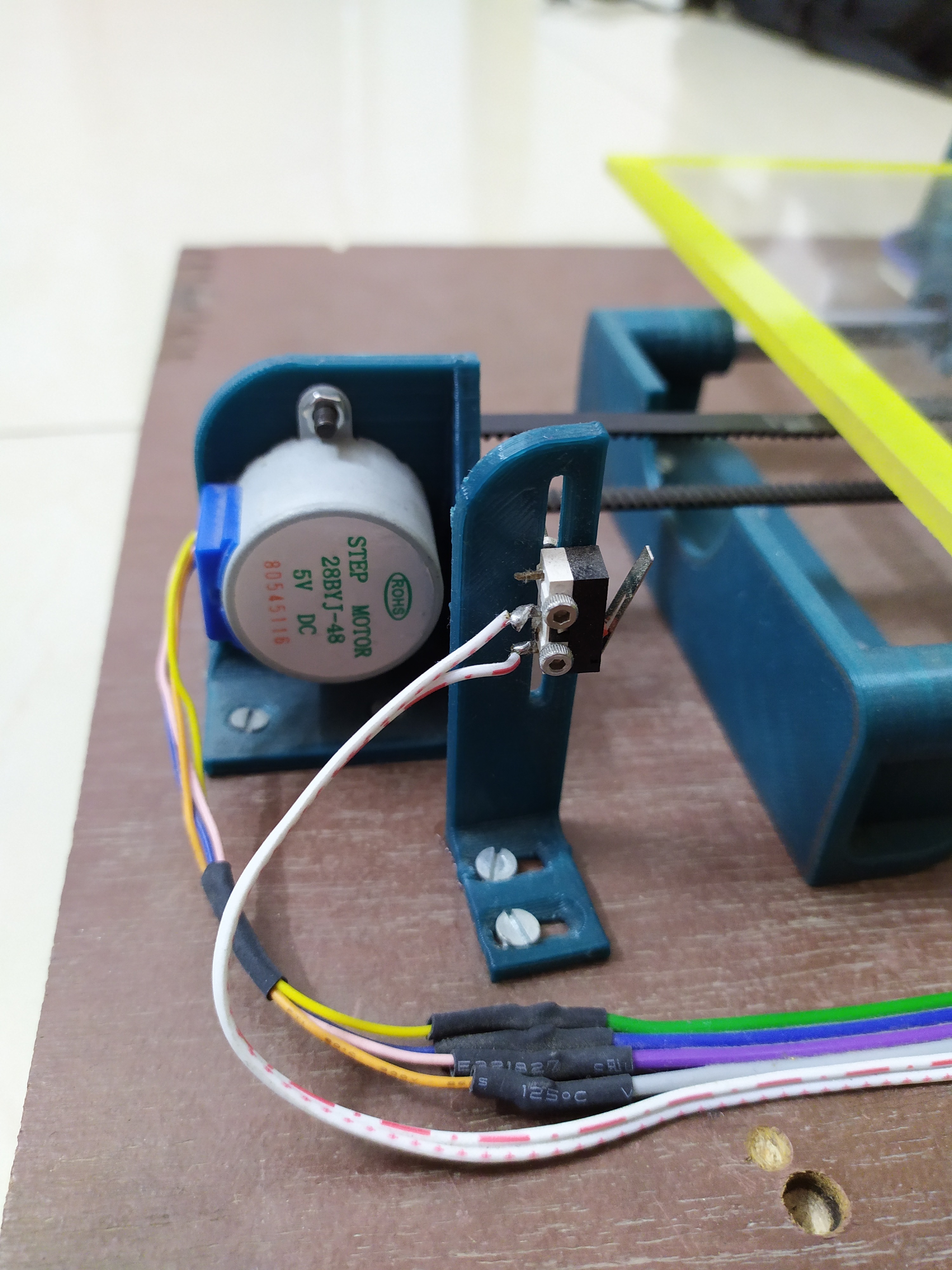
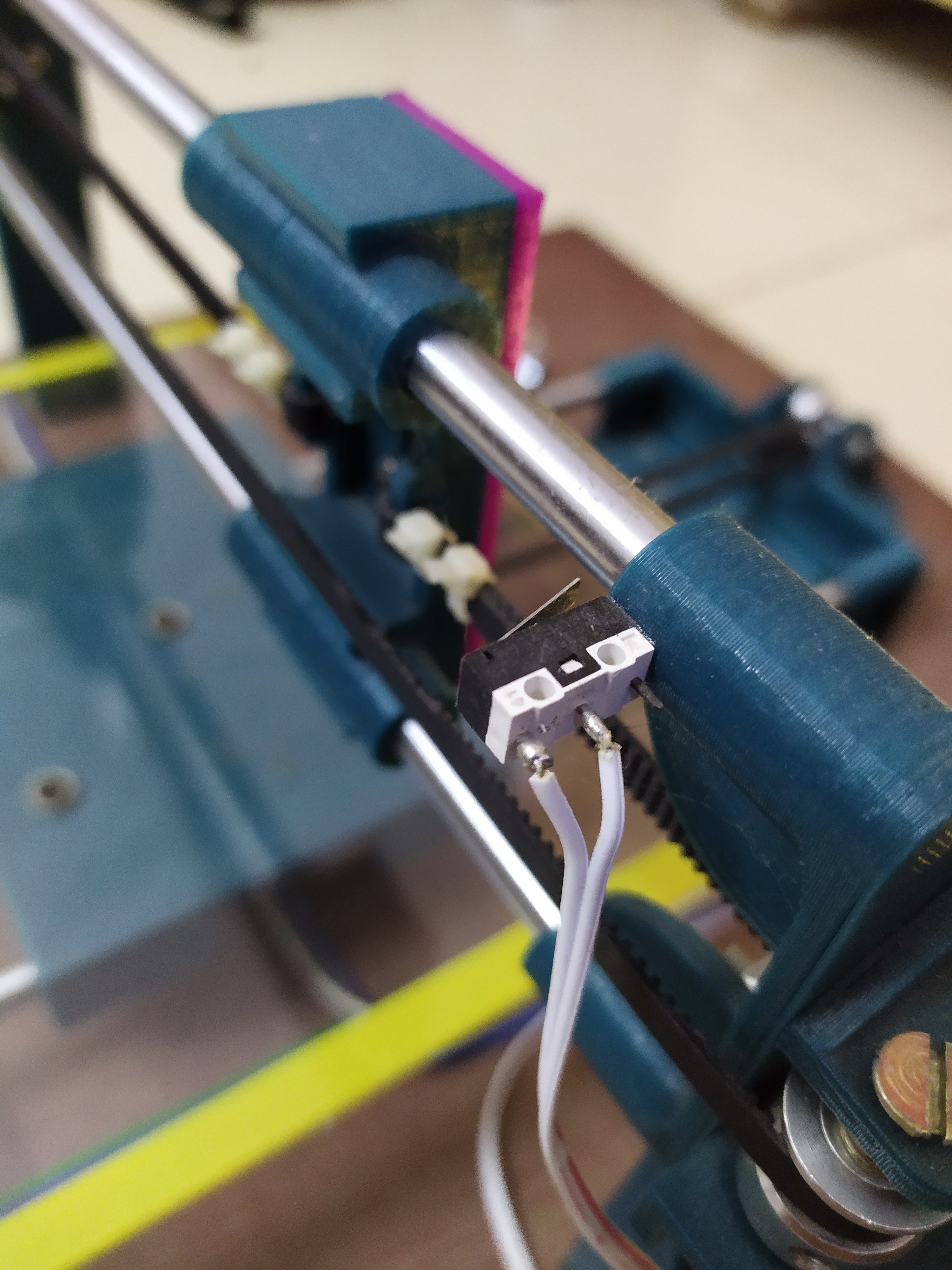
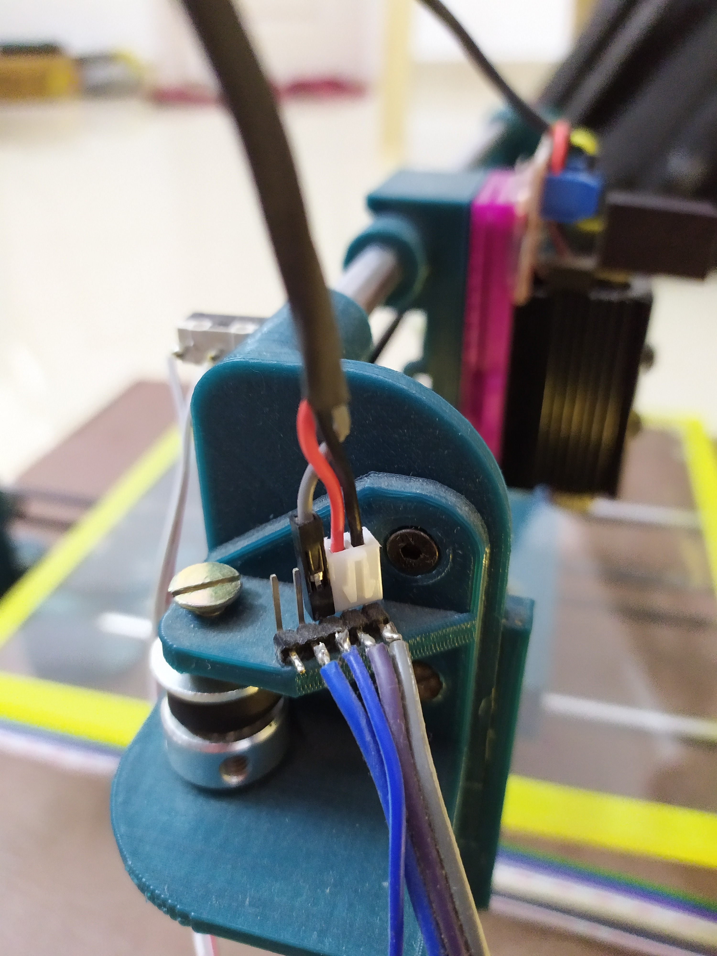
- The limit switches are attached in such a way that the button clicks 3mm before the bearings of each carriage collide with the rod holders.
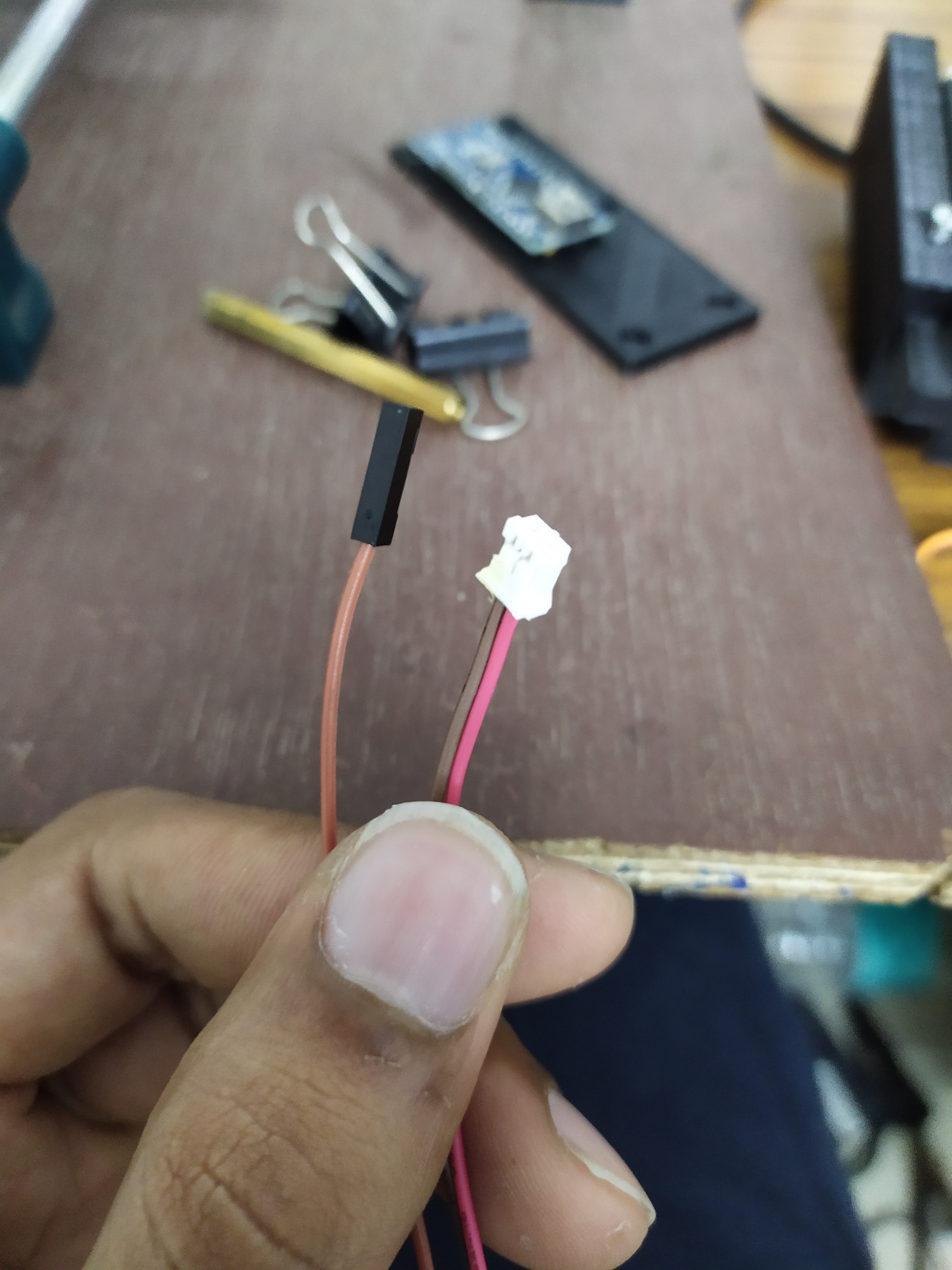
- The wires for the motors and limit switches are extended using ribbon wires and the connections are insulated using heat shrink insulation.close to the X-axis pulley as shown in the picture. This is the pin to which the laser module or the pin module will be plugged in. Solder +5 volts, GND and Sig from the CNC shield to these pins. When you are plugging in the modules, make sure its plugged in the right way.
- Add a set of male jumper pins
- The ribbon wires glued neatly to the plywood base using superglue.
We are using the boost converter here just to power the ICs in the A4988 motor driver on the CNC shield.
Each motor draws just 150 mA of current, Therefore you guys won't face any kind of heating of the boost converter.
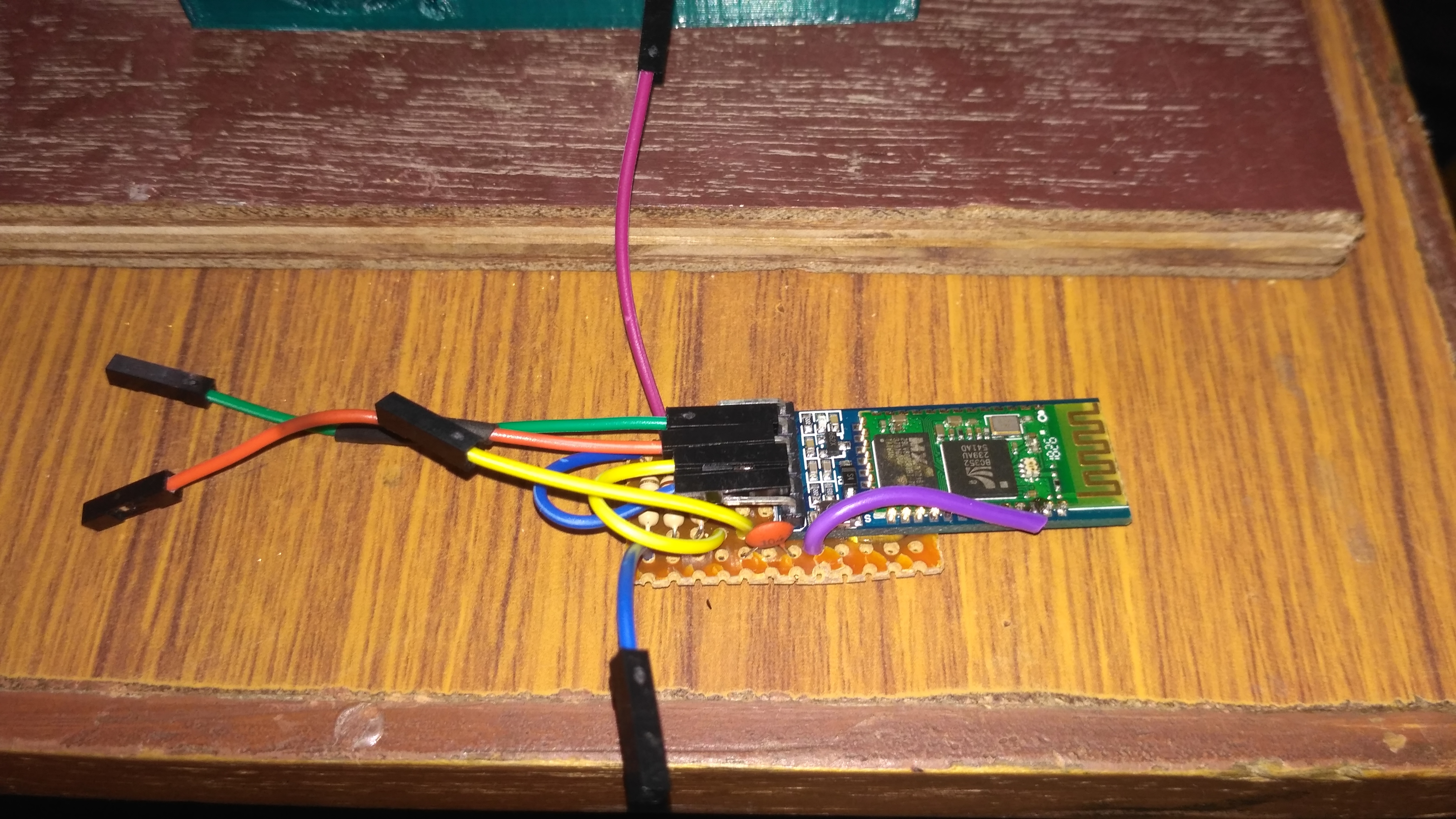
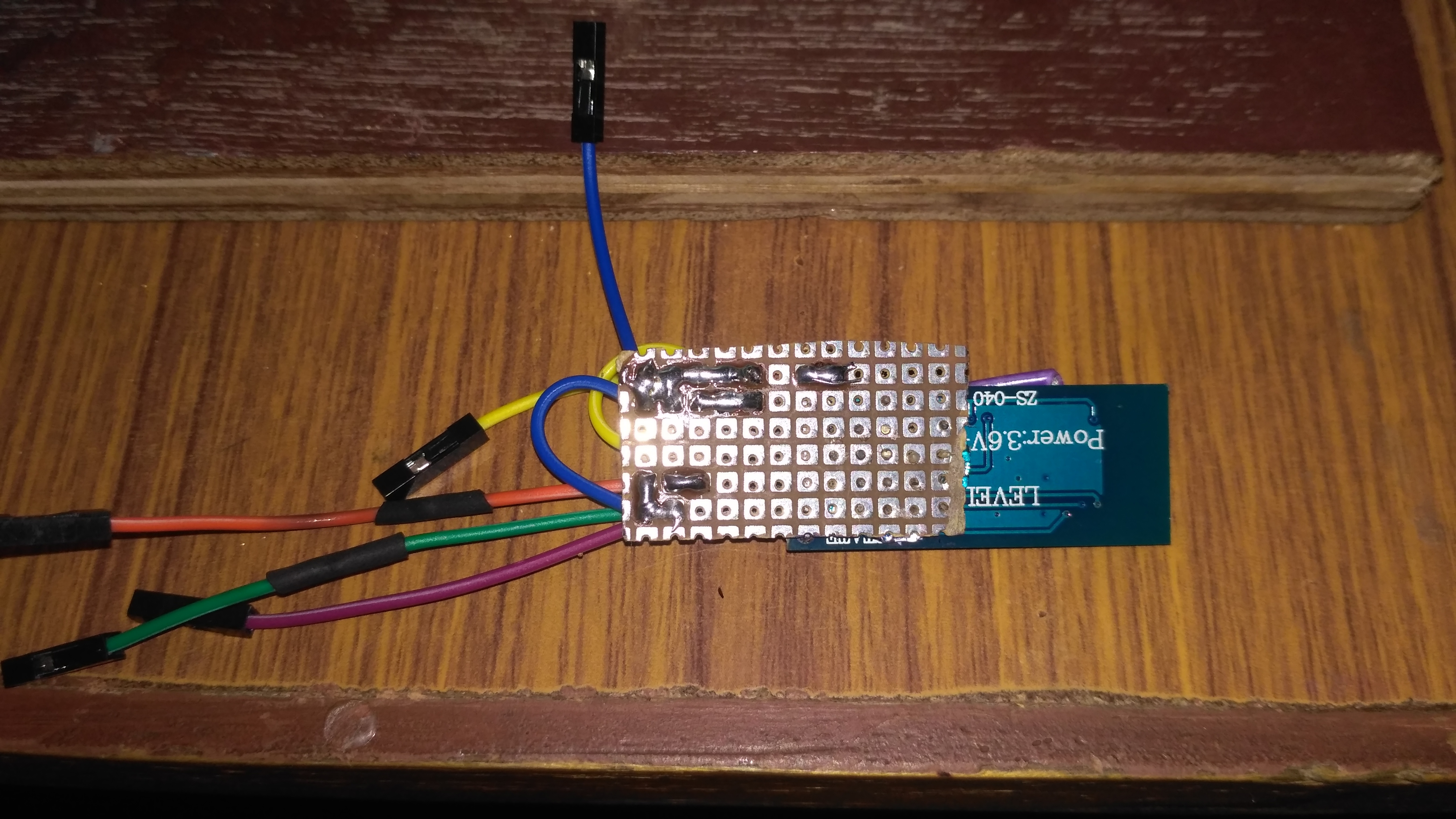
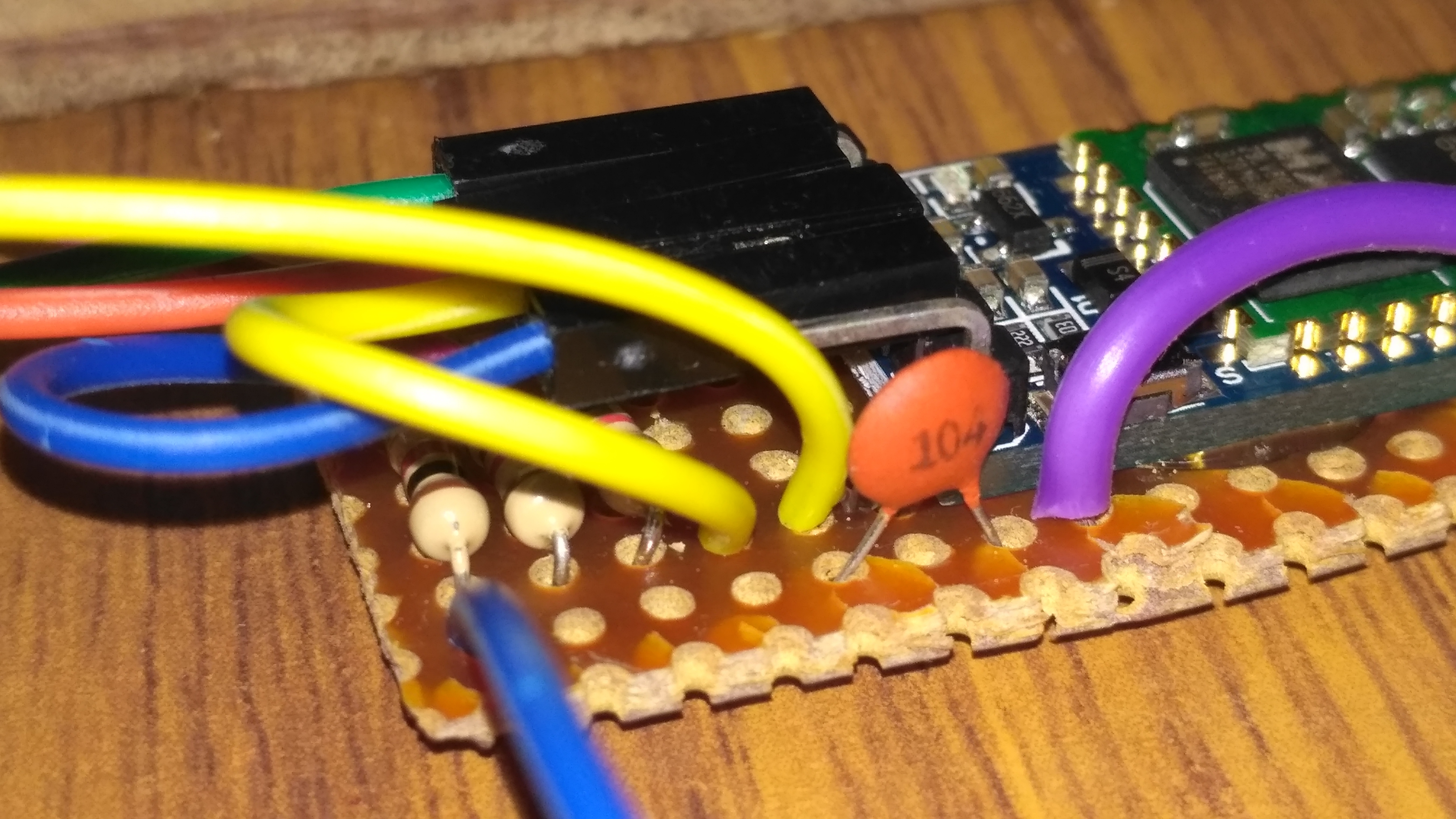
ADDING BLUETOOTH CONNECTIVITY
.jpeg)
.jpeg)
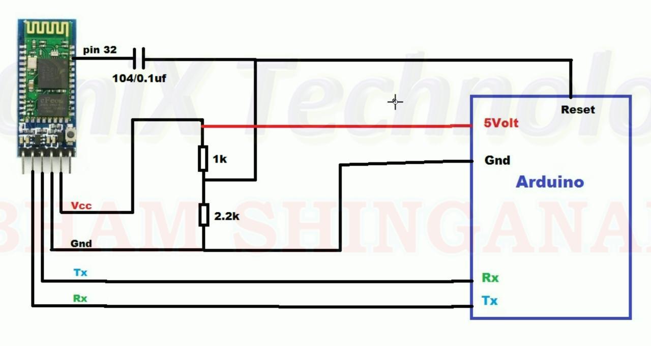

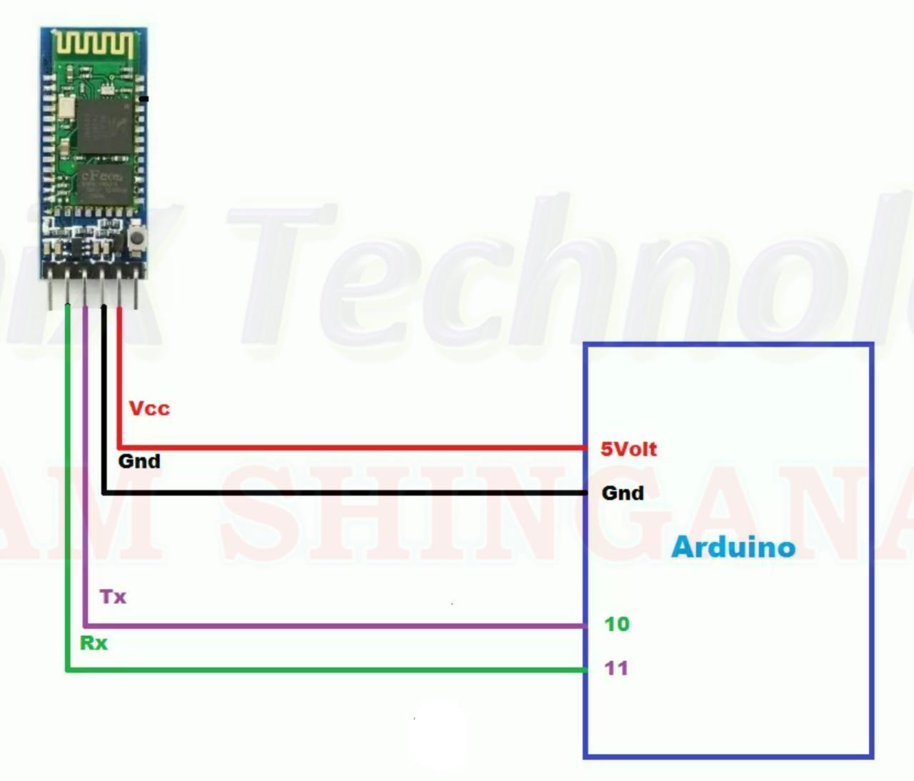
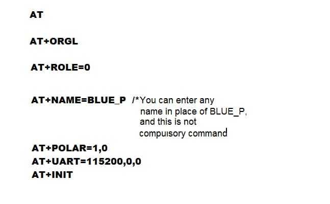
In order to send and receive data or in our case G-codes via the HC05 Bluetooth module, first, we should configure the module using AT commands.
- Connect the HC05 module to an Arduino Uno as seen in the first picture.
- Upload the code attached to this step into that Arduino.
- Now go to the serial monitor and type in the AT codes given in the 2nd picture.
- Once the configuration is done, disconnect the HC05 module from the Arduino you used to program it and connect to the Arduino CNC Shield according to the circuit diagram in the 3rd picture.
Since electronic components are used, I used a tiny piece of PCB to make things easier.
I attached ends of female jumper wires to the Bluetooth module so that it can be easily plugged into the CNC shield.
Downloads
CODING THE LASER ENGRAVER
This is a code from Github which I slightly modified
- In order to upload it First pair and connect your computer to the laser engraver via Bluetooth. Use the default password "1234" if asked for.
- Now open the attached code in Arduino IDE and select your Bluetooth port number from the ports in tools.
- Now hit the compile and upload button.
Downloads
LASER GRBL SOFTWARE CONFIGURATION
.png)
.png)
.png)
.png)
.png)
.png)
.png)
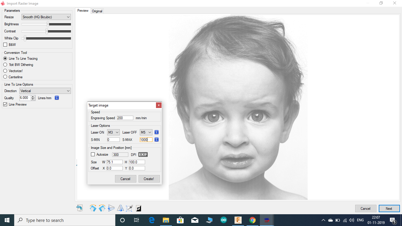
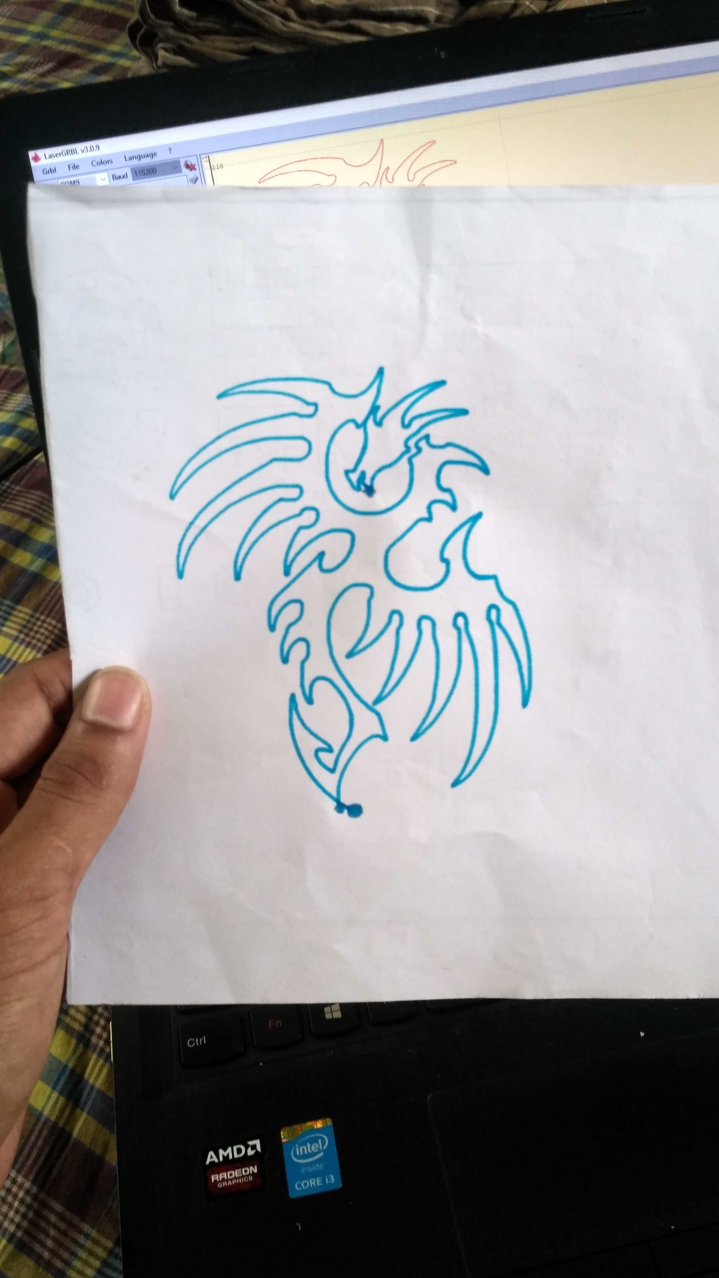
Laser GRBL is one of the best free G-code streamer software for DIY laser engravers. It can directly stream G codes to an Arduino via a com port. It has an inbuilt conversion tool to convert a picture into G codes.
Click here to download the software.
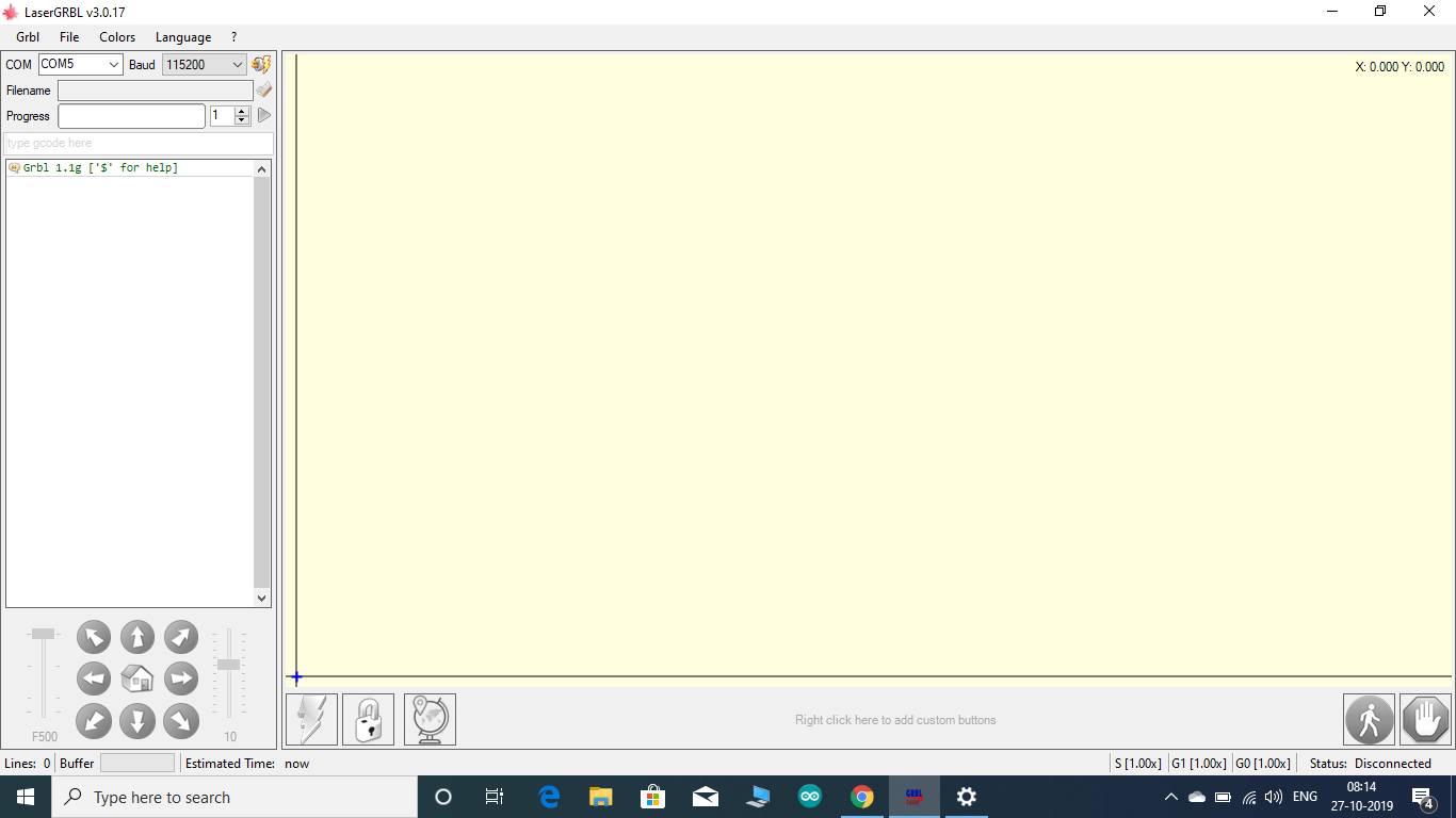
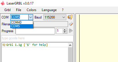
After installation of the software, follow the following steps for its configuration.
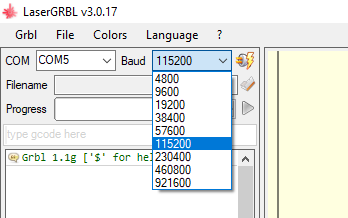
- Set the com port to which your laser engraver is connected.
- Set the baud rate at 115200
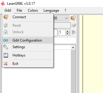
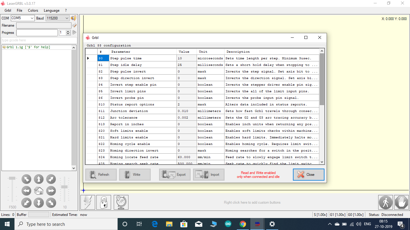
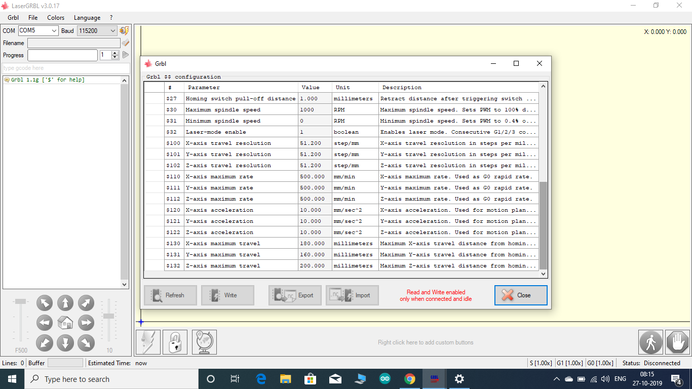
- Go to "Grbl" then Grbl Configuration" and set the values in the window that opens as seen in the pictures.
The configuration values can be modified according to what suits your machine best.
Once the configuration is done your laser engraver cum pen plotter is ready for action,
Go to the "files" button on the toolbar and open the design you would like to engrave or cut out.
There are options to select what type of engraving you would like to do, the power of the laser, etc which you can adjust according to the laser module you are using. Here I have attached pictures showing the settings I used.
Plugin the laser module and its time for some testing.
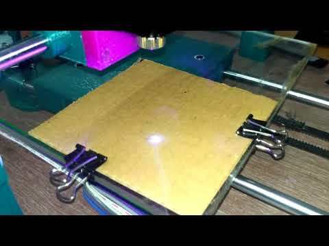
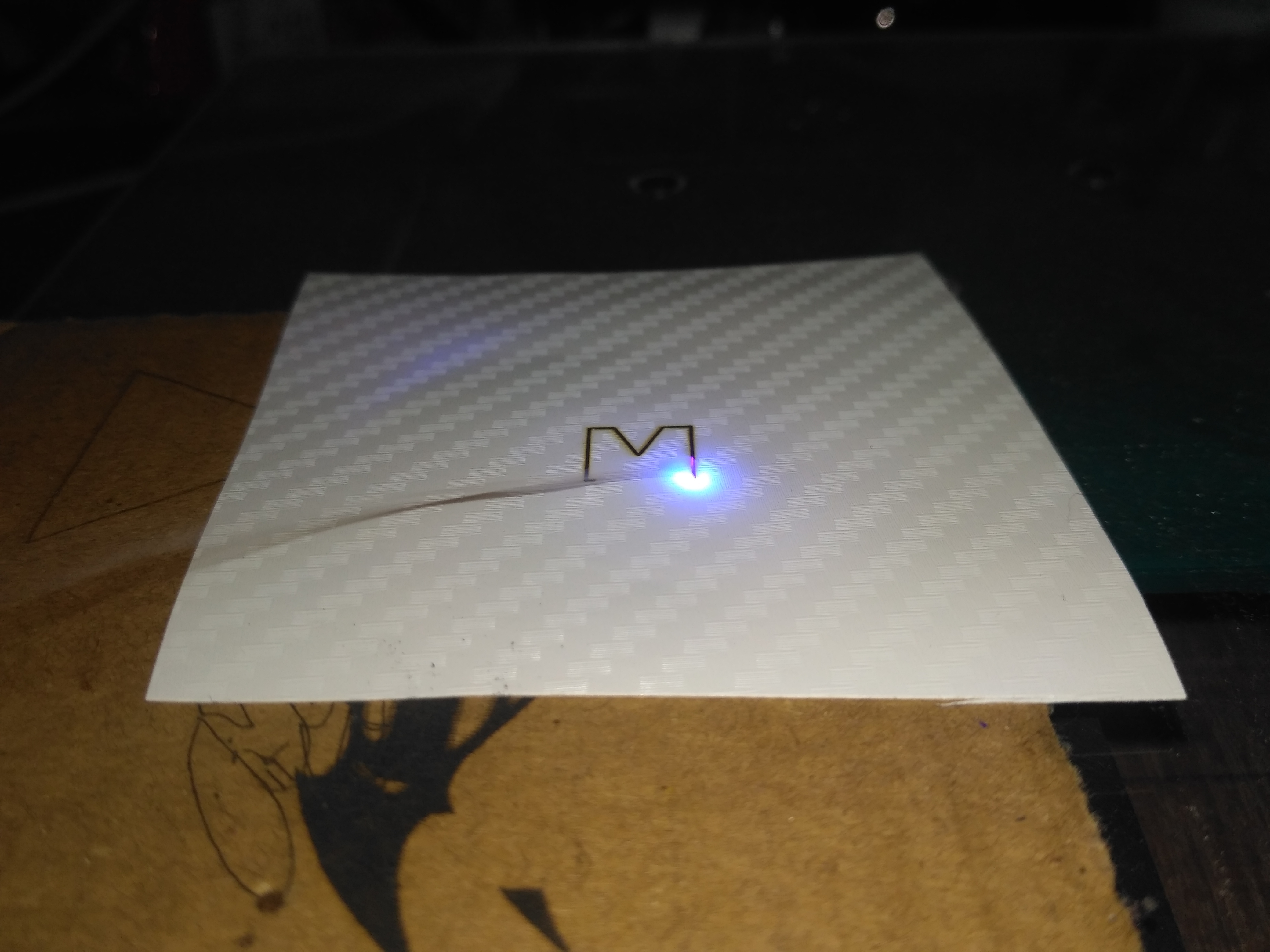
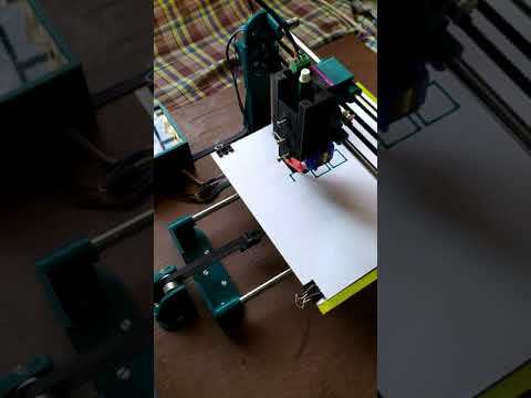
TESTING
.jpg)
.jpg)
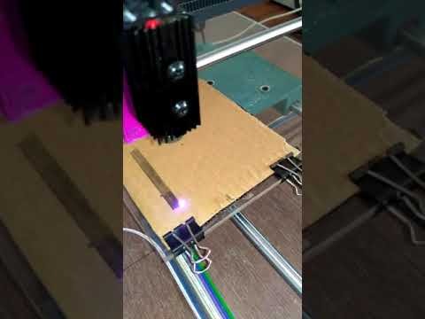
Once the laser is plugged in, its time to test the accuracy and precision of your machine.
There are a few things we should test:-
- If the X and Y-axis are moving in the correct direction.
- If the homing is working or not.
- If the motor is missing steps due to high friction or belts which are too tight.Adjust belt tension to fix this problem.
- If the dimension of the designs being printed matches the dimensions which you gave in the software.Recalculate the steps per mm according to the stepper motor you are using.
The belt tension can be adjusted using a 3D printed belt tensioner. Turn the M3 bolt on it until the right tension is attained. I have attached the STL file of the belt tensioner along with the other files to be 3D printed.
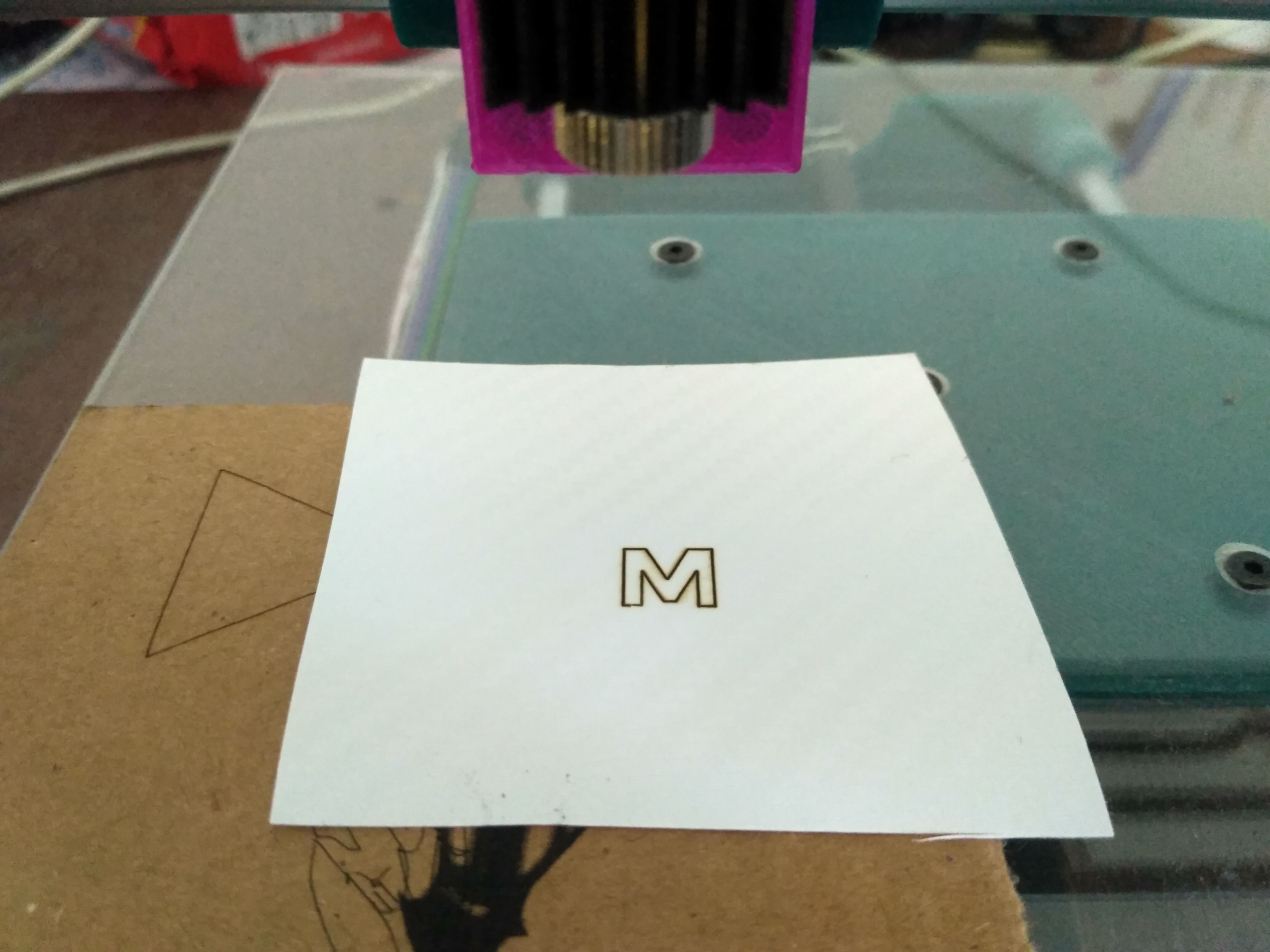
To test if the motor is missing steps and if the dimensions are right, print a simple continuous geometric figure like a square, triangle or a circle. If the laser starts from one point and perfectly stops at the same point it means that your laser is not missing a single step and is working perfectly. Once the triangle or square is printed, manually measure its dimensions using a ruler and see if it matches with the dimensions you gave.
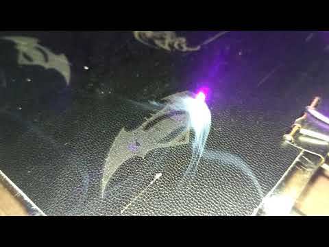
Here I have attached videos of the laser starting and perfectly stopping at the same point.
RESULTS
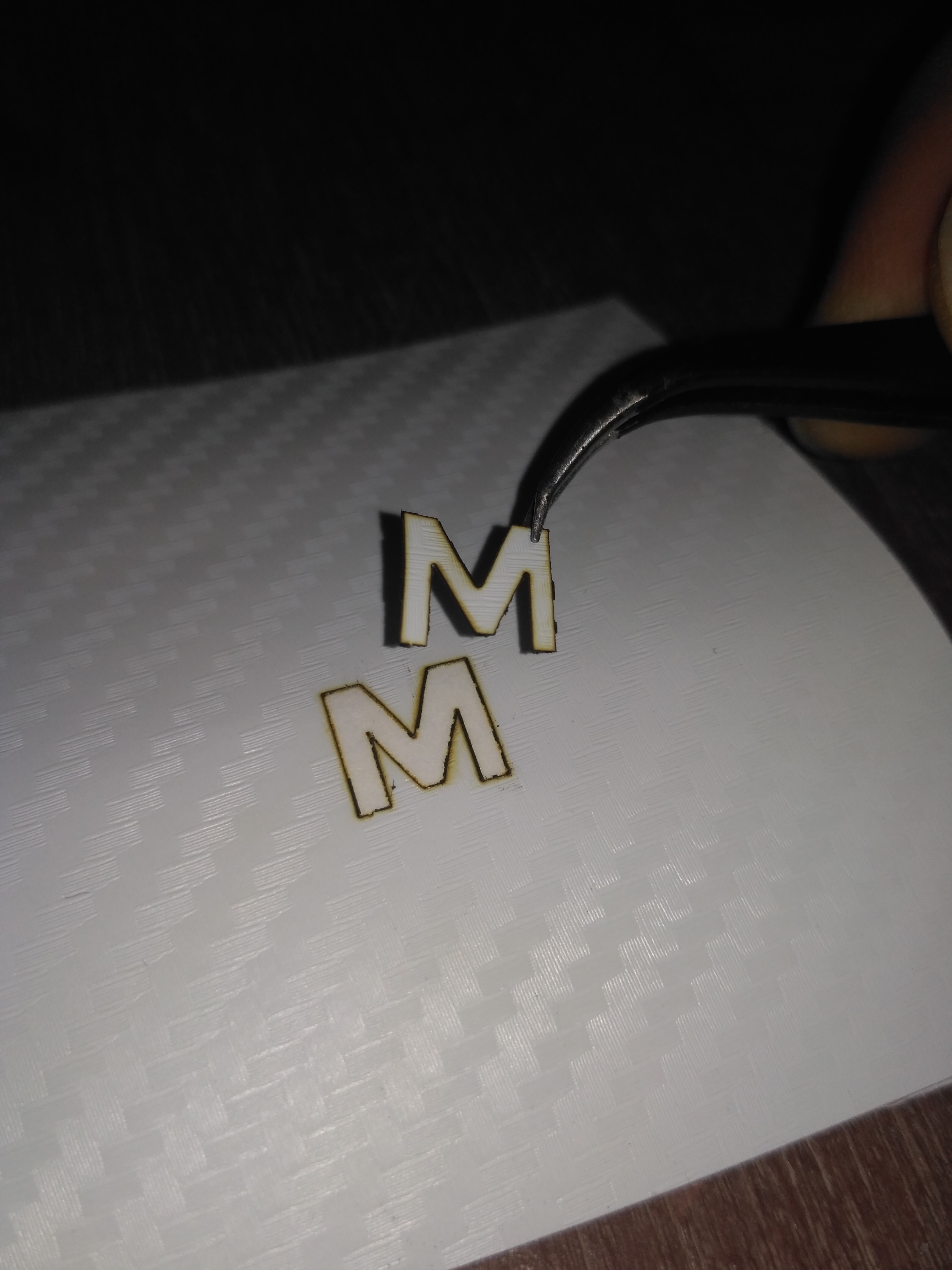
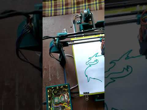
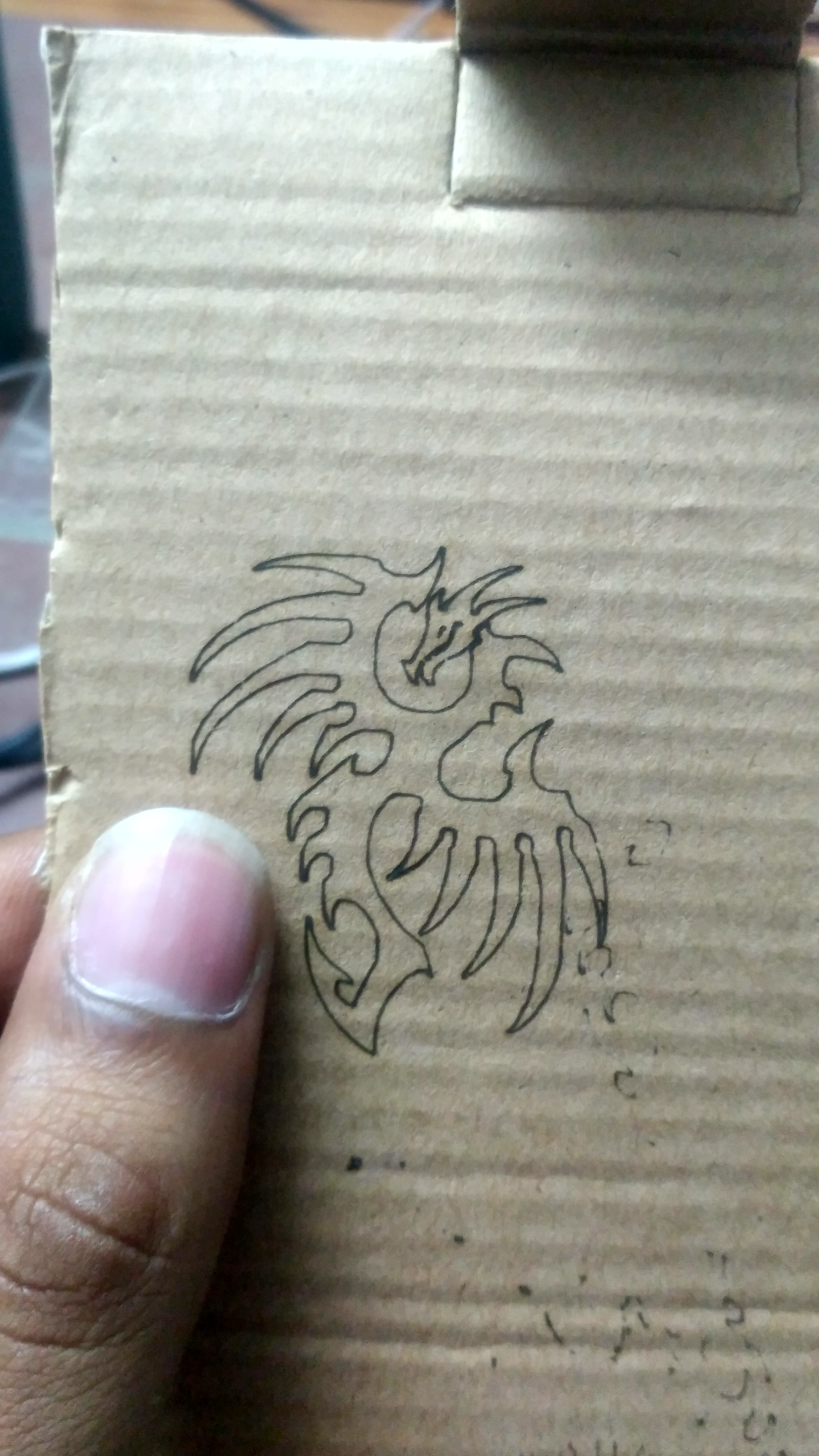
The machine came out amazing.
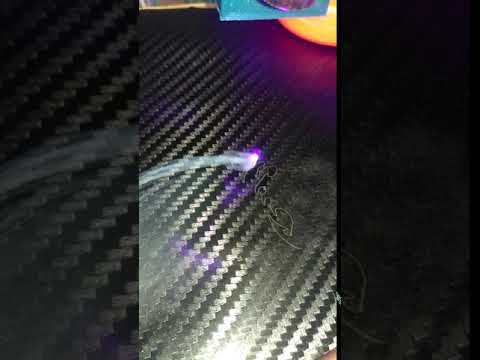
I was able to engrave on a variety of materials like wood, cardboard, leather, plastic, etc.
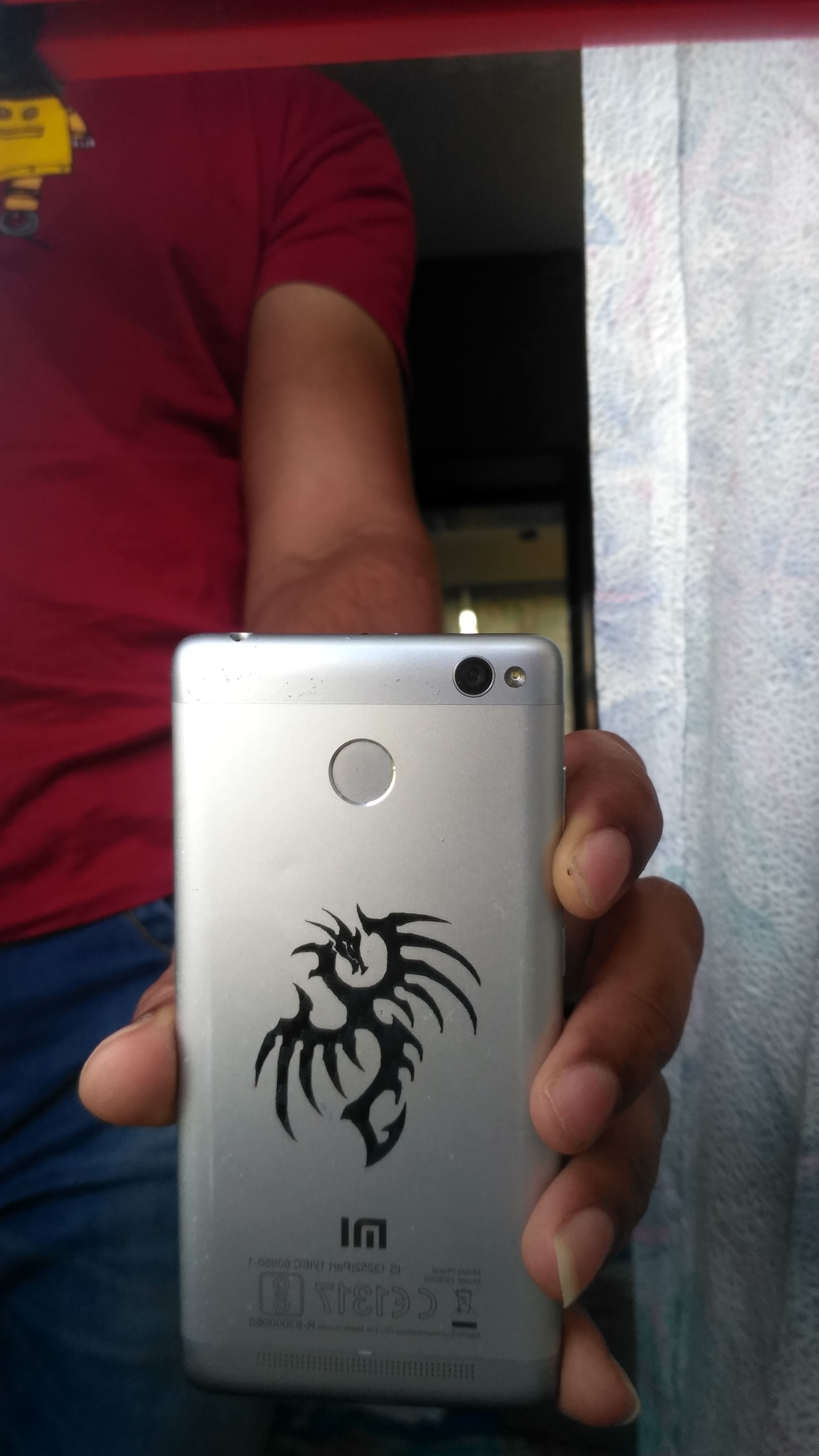
Since the motor had about 102 steps per mm, I was able to do tiny engravings with high details like the dragon I cut out from black stickers.
The engraver was running smoothly on a USB power supply without any problems.
I hope this instructable will help people looking forward to making their own laser engravers or pen plotters.
If anyone has any doubts or suggestions, please do let me know through the comments.