DESIGN AND BUILD YOUR OWN PORTABLE BLUETOOTH SPEAKER CUM POWER BANK
by patrick panikulam in Circuits > Speakers
7858 Views, 54 Favorites, 0 Comments
DESIGN AND BUILD YOUR OWN PORTABLE BLUETOOTH SPEAKER CUM POWER BANK


Hii everyone, so here is an instructable for people who Iove music and are looking forward to designing and building their own portable Bluetooth speakers. This is an easy to build speaker which sounds amazing, looks beautiful and small enough to carry around in your bag. It can be used as a power bank as well so that you don't have to worry about charging your phone on the move. I have always felt that cylindrical speakers sound better than cuboidal ones, so this time I have decided to try this design. The speaker comes with the latest speaker technology like neodymium full-range drivers, passive radiators, and a stereo class D amplifier.
Speaker Specifications:-
- 12 watts power
- Length: 160mm ,Diameter: 75mm
- 5200 mah rechargeable battery, 6-8 hours of playtime
- 1.75-inch neodymium full-range drivers
- Dual face to face passive radiator for maximum bass and minimal vibrations.
- 5200 mah power bank capability.
- Led battery indicator
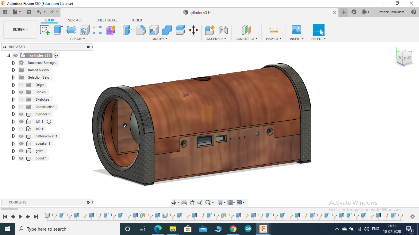
CAD in Autodesk Fusion 360
.png)
.png)
.png)
FUSION 360 is one of those amazing platforms which allows you to convert those design ideas inside your head into reality. It really helps in expressing your idea about something to others. It's really easy to learn and use. Assembly of the components can be done easily and it helps in the validation of your design by checking for collisions and other problems
Unlike other cad software, one cool thing about fusion 360 is that it allows the designing of multiple components on the same screen with reference to other components, ie the model can be designed in an assembled manner. Fusion 360 also allows us to choose the appearance and material of the components so that your final design looks like the real thing. Fusion 360 also lets us convert and save the designed components directly in STL format which makes it easier for the next stage of 3D printing.
For this project, I first took the measurements of each component using a vernier caliper, using these dimensions along with the cylindrical air volume dimensions of similar type speakers already in the market I determined the optimum length and diameter required for best performance. For maximum performance, the speaker chamber has to be maintained airtight throughout the speaker's life. So I designed two separate chambers for the future replaceable components like the batteries and charging modules which can easily be accessed from the outside without getting into the main speaker chamber.
COMPONENTS AND TOOLS


COMPONENTS :
- 1.75 Inch 8 Ohm 7W Speakers X 2 (AliExpress)
- 62mm passive radiator X 2 (AliExpress)
- 6W + 6W stereo receiver Bluetooth amplifier X 1 (AliExpress)
- 1s 18650 protection board X 1 (AliExpress)
- 2600 mah 18650 rechargeable battery X 2 (AliExpress)
- USB boost module X 1 (AliExpress)
- 12mm waterproof led push button X 1 (AliExpress)
- Battery contact plate and spring X 2 (AliExpress)
- Wood Grain Vinyl wrap (AliExpress)
- Carbon fiber vinyl wrap (AliExpress)
- BC547 transistor X 1
- 1K resistor X 1
- 16-25 volt,1000uf capacitor X 2
- M3 nuts and bolts
TOOLS:
- 3D printer
- Allen key set
- Soldering iron
- razor blade
- scissors
- Screwdriver
- Rubber-based adhesive (fevi bond)
- Foam based double-sided tape
- Hot glue
- Pliers
3D PRINTED COMPONENTS AND THEIR STL FILES


All the parts were printed using black PLA with 100% infill for maximum durability. The cylindrical body and side caps should be printed vertically for best finish and strength. The layer height was set for the best finish so that vinyl wrap sticks easily. Only the main body has to be printed with supports.
3D printer : Tevo Tarantula
Material : PLA, BLACK
Temperature : 212 C
Layer height : 0.1mm
Infill : 100%
CIRCUIT PREPARATION


Most Chinese amplifier boards are designed in a manner to make it cheaper and smaller. There are some easy tricks to improve their performance quality.
So the first thing I noticed about this board is that despite having a battery port and a micro USB female port for charging the batteries, the board was missing IC components for battery overcharge and discharge protection. Therefore I attached a separate 1s BMS between the battery terminal of the board and the batteries as seen in the circuit diagram and pictures. This ensures that the batteries are always safe.
The second thing I noticed was a slight disruption when the volume was maxed out. This was happening because the tiny capacitors attached parallel to each of the Amplifier ICs power inputs were not able to hold enough charge to power the amplifier at high volumes. So this problem was solved by using two larger capacitors parallel to the old ones.
Once this was done, two wires of enough lengths were soldered to the speaker output terminals of the board.
SYNCING THE BUILT IN LED WITH THE RING LIGHT OF THE POWER BUTTON


The amplifier board has a tiny builtin SMD led that lights up and flashes according to the Bluetooth connection status and the music. But the problem is, this led won't be visible from the outside once the amplifier board is fixed inside the speakers.
So this led has to be synced with the ring light around the power button. The voltage signal used to power the SMD cannot directly power the ring light as the ring light needs more power. So this voltage signal is used to trigger or switch a transistor which in turn switches on the ring light using power directly from the batteries.
- The wire connections for doing this is shown in the Circuit diagram in the previous step.
- Connect a 1K resistor to the pin D1 of the Bluetooth chip
- Connect the other end of the resistor to the base of the BC547 transistor
- Connect the emittor of the transistor to the ground.
- Connect the collector of the transistor to the negative terminal of the Ring light.
- Connect the positive terminal of the Ring light to the positive terminal of the battery


- The power wires are pulled out through the holes provided in the chamber in which the power bank board has to be placed.
- These wires are carefully soldered to the power bank module according to the correct polarity and then glue is poured around the hole through which the wires came in to prevent air leakage.
- Double-sided tape is applied on the power bank module and it's attached in its chamber as seen in the picture.
- Glue is applied on the amplifier board and its attached inside the speaker's body as seen in the picture.
SPEAKER ATTACHMENT


As mentioned earlier, it's very important that the speaker chamber is airtight for the proper operation of the passive radiators. Therefore a piece of foam-based double-sided tape is used as a soft washer to prevent leakage once the bolts are tightened. The speakers are attached using 30mm M3 bolts and nuts.
The excess amount of foam tape is sliced off using a razor blade to make it look neat.


- The soldering points of the battery plate and spring are first inserted through the slots provided for it on each end of the battery chamber.
- The plate comes on the positive terminal and the spring on the negative terminal of the battery.
- The plates and springs are glued to the chamber as seen in the picture.
- The power wires are soldered to the soldering points that were inserted earlier.
- Glue is used at the make the chamber leakproof at the inserts.
APPLYING VINYL TO THE BODY


- A strip of the vinyl slightly wider than the speaker's body and longer than the speaker circumference is cut out.
- The vinyl is applied carefully making sure the body is covered properly.
- The extra vinyl around the chamber openings and ports are cut off using a razor blade.
- Heat the vinyl around the power button hole to bend it in neatly.
APPLYING VINYL TO THE SIDE CAPS


- The side caps are sanded using very fine sandpaper to make all the surfaces smooth for stickering.
- Carbon fiber vinyl is apples on the face and circumference of the end caps.
- The excess vinyl from the sides is trimmed off with scissors and the circular hole is neatly cut out by running a razor along the circumference of the opening.


- The rubber-based adhesive is applied ob both the passive radiator and the end caps along the circumference.
- Wait for 5 minutes for the glue to dry slightly.
- Keep the passive radiators pressed on the endcaps using a light load until the glue dries.
ATTACHING THE POWER BUTTON


- The four wires (led +, led-, battery -, amplifier -) is pulled in through the button nut.
- Then the four wires are pulled out through the button opening on the speaker's body.
- The wires are soldered to the switch at the correct marked terminals.
- The Switch is fastened to the body using the nut with the help of a plier.
CLOSING THE BATTERY CHAMBER


- Two fully charged batteries are inserted into the battery compartment
- A little bit of hot glue is used just to make sure the batteries stay in place.
- The battery cover is closed and fastened using two M3 bolts with the help of an Allen key.
ATTACHING THE SIDE CAPS AND GRILLS


- The rubber-based adhesive is applied along the circumference of the speaker body's ends as well as inside the end caps.
- Wait for 5 minutes for the glue to dry slightly
- The end caps are pressed on to either side of the speaker body and kept under load until the glue dries.
- Similarly, the speaker grills are also glued on to the speaker body.


And there you have it, the speaker built is complete. If any of you guys have any doubts or queries , feel free to mention it in the comments.I'll be definitely answering all questions.
Thankyou