DCD201FinalTroyP.
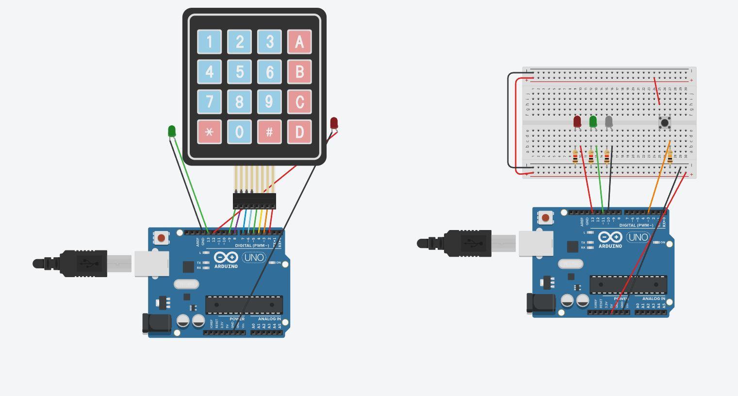
For my holiday escape room puzzle, you'll set up two different Arduino units and breadboards.to setup both parts. The puzzle involves a trio of festive lights that, after pressing a button, will light up in a certain order to reveal a code. The player will use that code to put into the 4x4 keypad to get the LED to turn green. This will solve the puzzle!
The Arduino Code
For this puzzle, you want to plug in the attached code that will light up when you press the push button; as well as have the keypad function correctly with the LEDs whenever you input the correct password. The first code will light up the lights whenever you press the button due to the connection with the code. The second one uses the many cables connected to the Arduino circuit to make the numbers/letters have a correct input.
Hardware Setup: Keypad
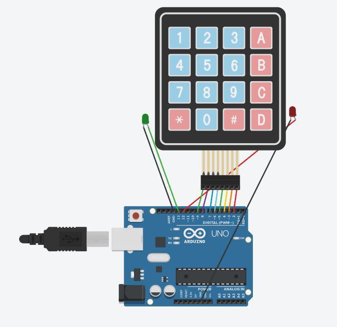
- Connect the Keypad to the following numbers on the digital pin of the Arduino: 2,3,4,5,6,7,8,9.
- Connect the red LED to ground power (GND) and digital pin 12
- Connect the Green LED to ground digital (GND) and digital pin 13.
- Plug in the Arduino Unit to a USB Port in the computer.
Hardware Setup: Multi LED
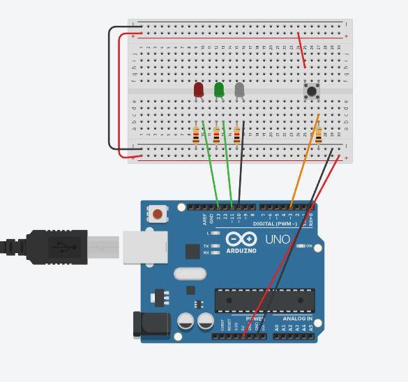
- Connect the top left of the pushbutton to F 25 on the breadboard.
- Connect the long end of the Red LED to the left; Put it in E 9
- Connect the long end of the Green LED to the left; Put it in E 12
- Connect the long end of the White LED to the left; Put it in E 15
- Connect a 1k resistor to B 9 and have it connect with the ground terminal
- Connect a 1k resistor to B 12 and have it connect with the ground terminal
- Connect a 1k resistor to B 15 and have it connect with the ground terminal
- Connect a cable to B 10 and then digital pin 13
- Connect a cable to B 13 and then digital pin 11
- Connect a cable to B 16 and then digital pin 10
- Connect a cable to C 27 and then digital pin 3
- Connect a 10k resistor to B 27 and have it connect with the ground terminal
- Connect a cable from the ground terminal to the Ground section in the Arduino (GND)
- Connect a cable from the positive terminal of the breadboard to the 5v on power to provide power.
- Connect a cable from the positive terminal of the top to positive on the bottom
- Connect a cable from the negative terminal of the top to negative on the bottom
How to Play!
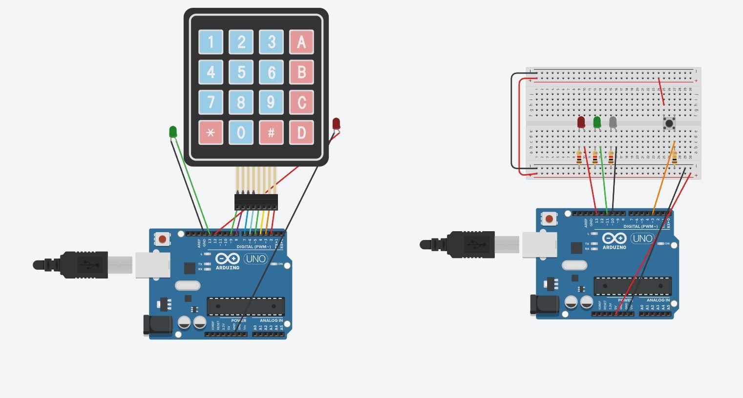
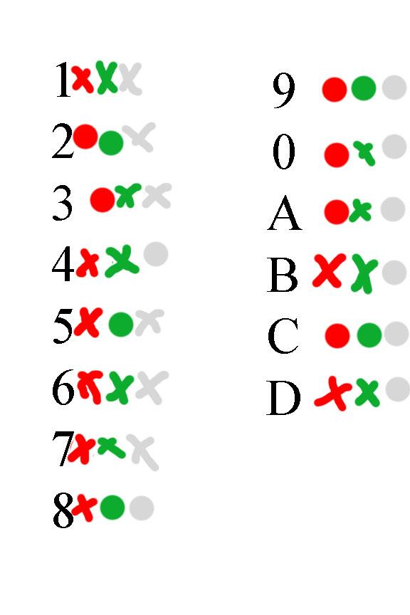
To play the puzzle, you must do the proper setup explained above. After it is setup, you want to press the button to show you a series of colors. After you see the colors, you look to a color sheet provided, and when you figure out the 4 characters its displaying you input them into the keypad. If done correctly, the green light should shine after inputting the final number/letter
Try It
I apologize for not posting with a proper Embedded link. I could not get this to work and could not understand why. However I will put a link to the page in here to help get to and look at it.
Link: https://www.tinkercad.com/things/lvjYDBfcPnI