DC-Rover


DC-Rover is a simple and easy-to-build robotic camera rover that uses a Raspberry Pi Zero, Adafruit's DC Motor Bonnet, a 5MP Pi-Cam, and a 5v regulator.
This instructable will guide you through the build process, together with an example code that lets you control the rover, take photos/videos, using a game controller over Bluetooth connection to the Pi 0.
There's also an "optional" spring&motor-controlled toy artillery/cannon you can build (link coming soon) that can be attached to the rover for additional fun.
Note: Before attempting this project, please be aware that it is assumed that you have some experience with Raspberry Pi, Raspberry Pi Zero, and are aware of its fundamental operation, including, powering it up, Raspbian installation (NOOBS software), and other basic functionality. If not, please click here.
Credit to Approximate Engineering Input Library and Adafruit's Motorkit Library.
Supplies
Fore-warning: Some parts are small and can be a choking hazard. Please keep away from children or pets.
Materials Needed for this Project:
- Raspberry Pi Zero W (No Header) with the latest Raspbian already installed and connected to your local WiFi
- Adafruit DC Motor Bonnet
- DC Rover 3d Printed Parts (download the files and print yourself).
- 4 x TT DC Motors (for wheels) (Link)
- 4 x Mecanum Wheels (two pairs of left and right) (Link)
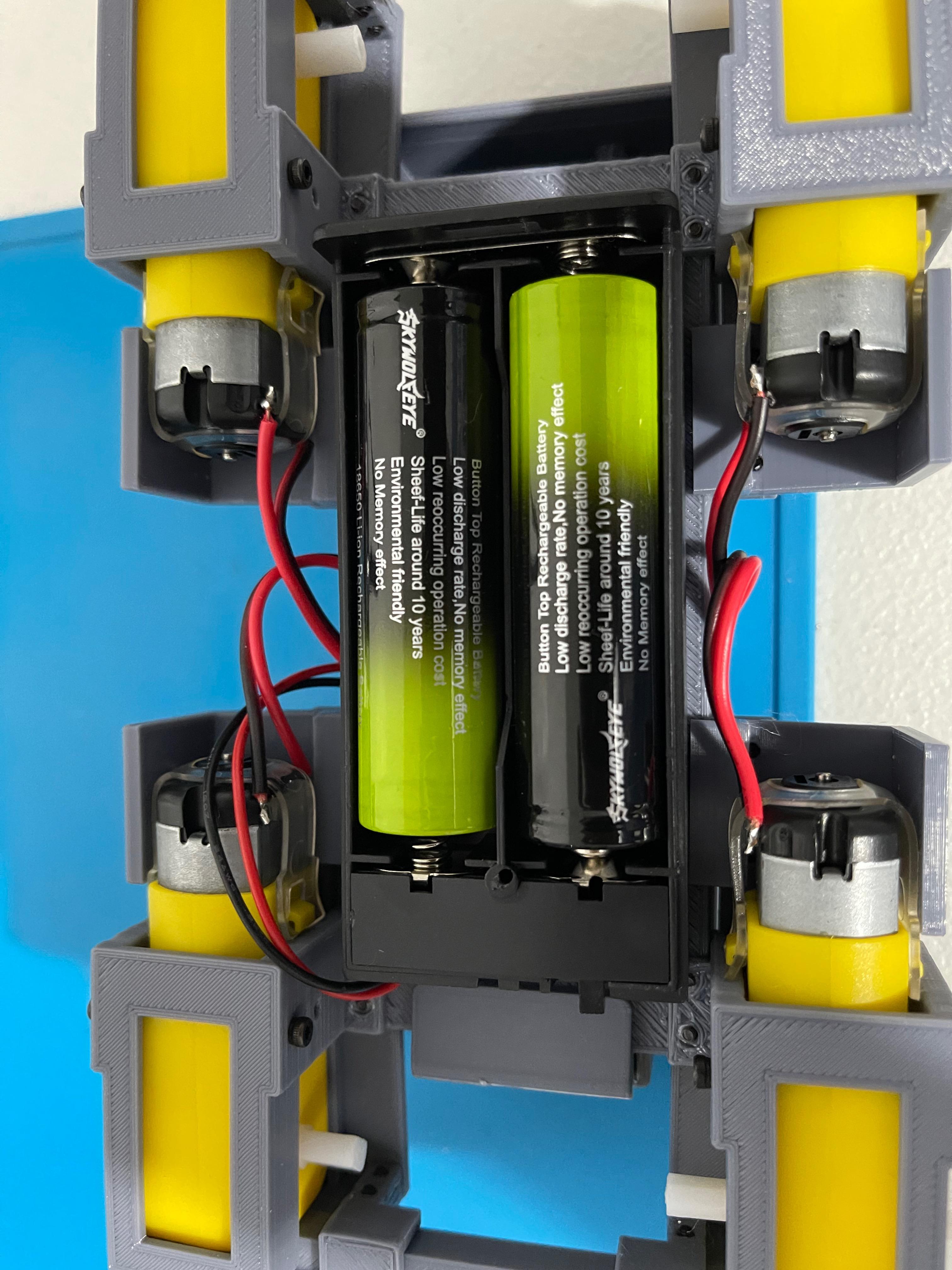
- 2 x 18650 3.7v Batteries (at least 2500 maH each)
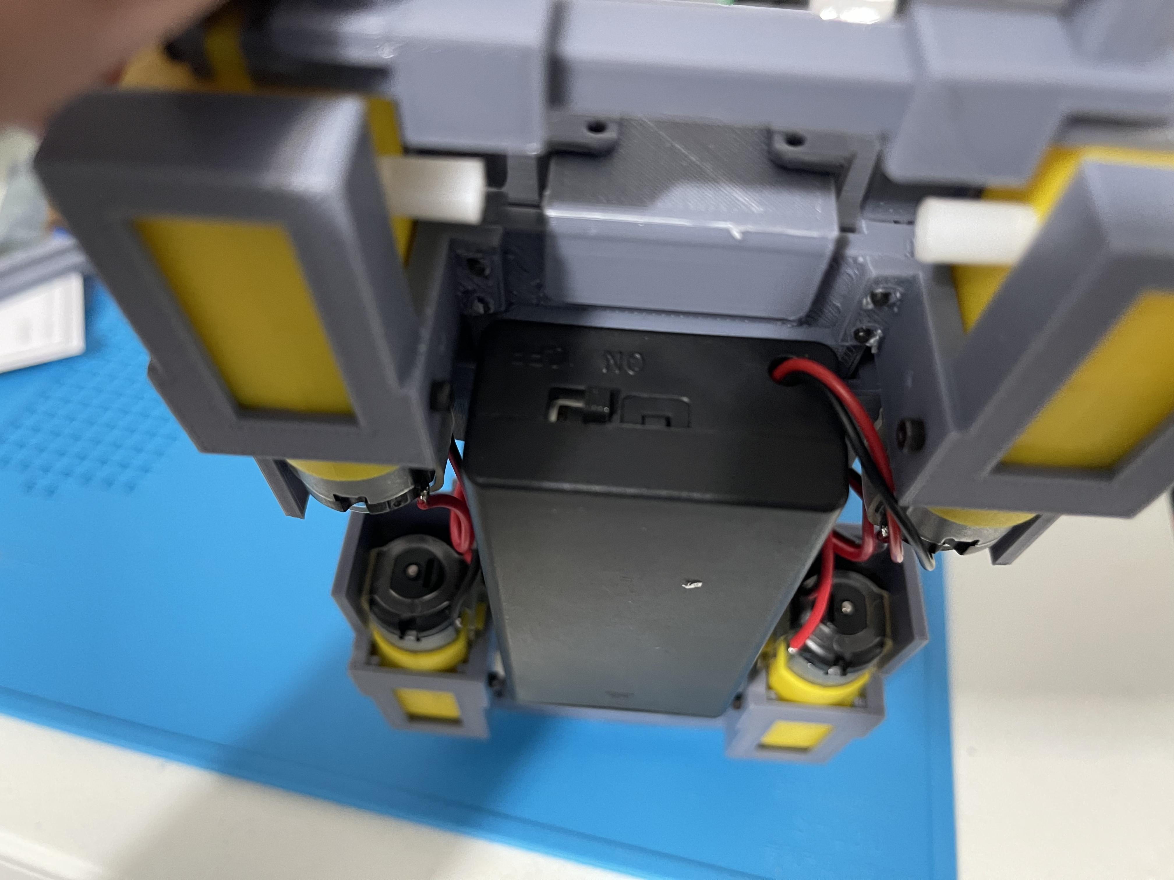
- 18650 Covered Battery Holder with On/Off switch (Link)
- DC Voltage Buck Converter (Link)
- Pi Camera with ribbon cable for Pi Zero (Link)
- Male to Female Dupont Wires
- 22 AWG Red/Black Coated Wires
- Assorted-length Hex-head M2 Screws (Link)
- 4 x 6mm M3 Self-tapping Screws (Assorted Kit Available - Link)
- 21mm 1 x 40 or 2 x 20 Male Headers (for Pi Zero) (Link)
- Game Controller (PS4 or Xbox recommended)
Tools Needed:
- 3d Printer
- Soldering Iron
- M2 Hex Head Key or Screwdriver
- M3 Screwdriver
- Digital Multi-Meter
Note: When tightening the screws, only use a manual driver/key and do not "over-torque".
Always click (enlarge) the images to see the image notes.
Software Used in the Design:
- Tinkercad for the 3d Printable Rover parts
- Python 3 for the Sample Code
Attach the Battery Holder to the Rover Base
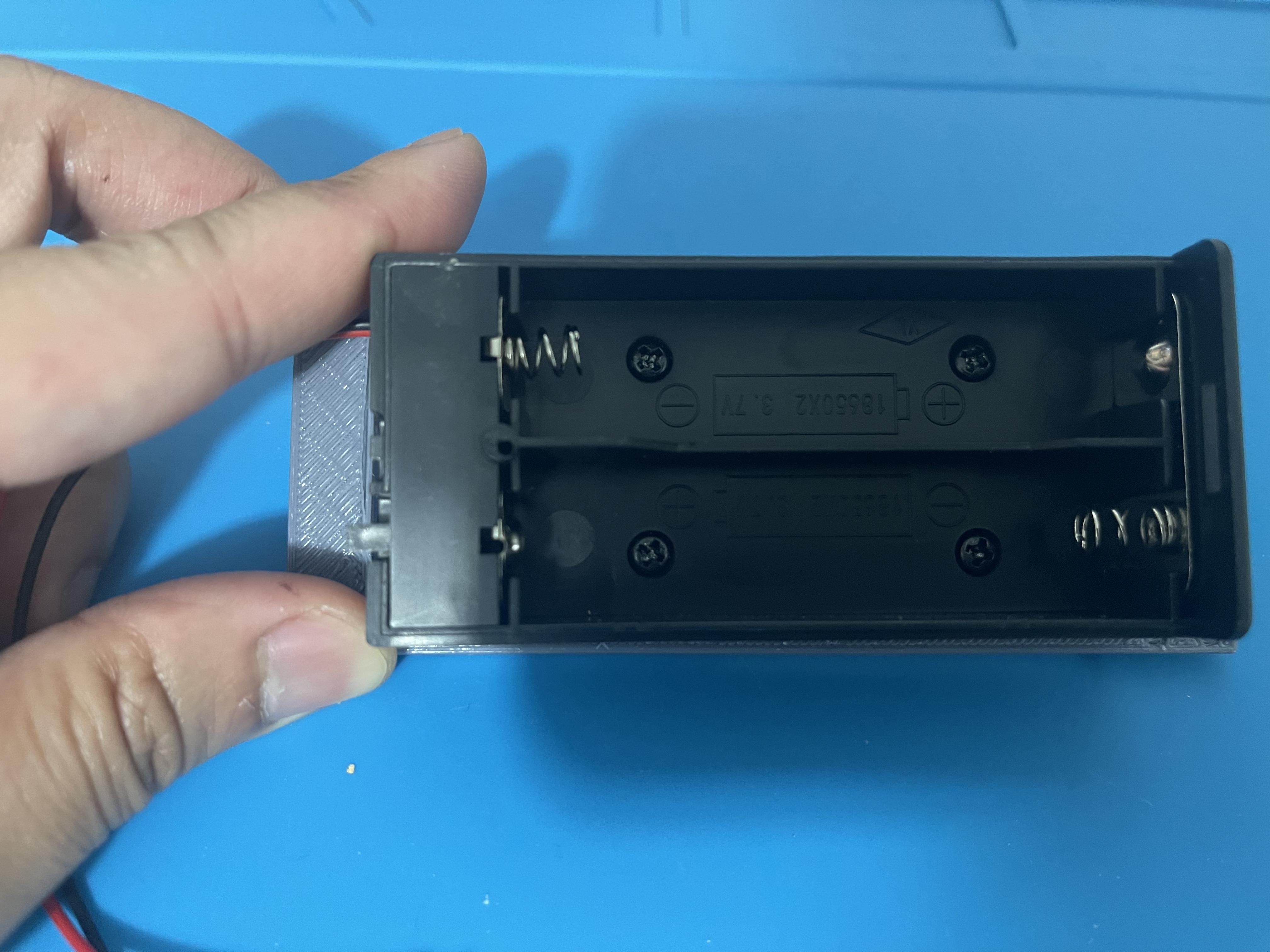
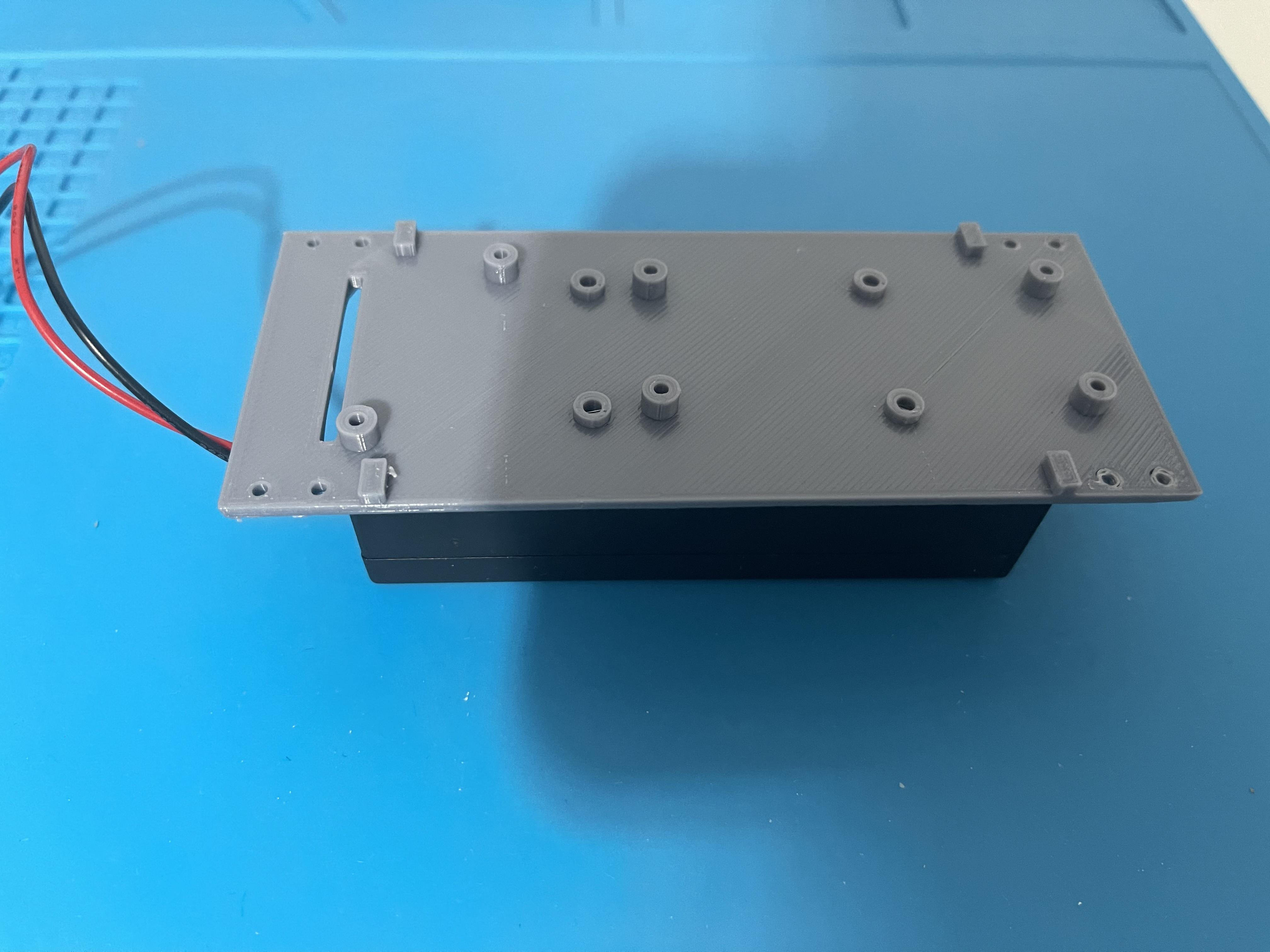
Use 6mm M3 self tapping screws. See notes on the images.
Attach the DC Motors to Their Mounts
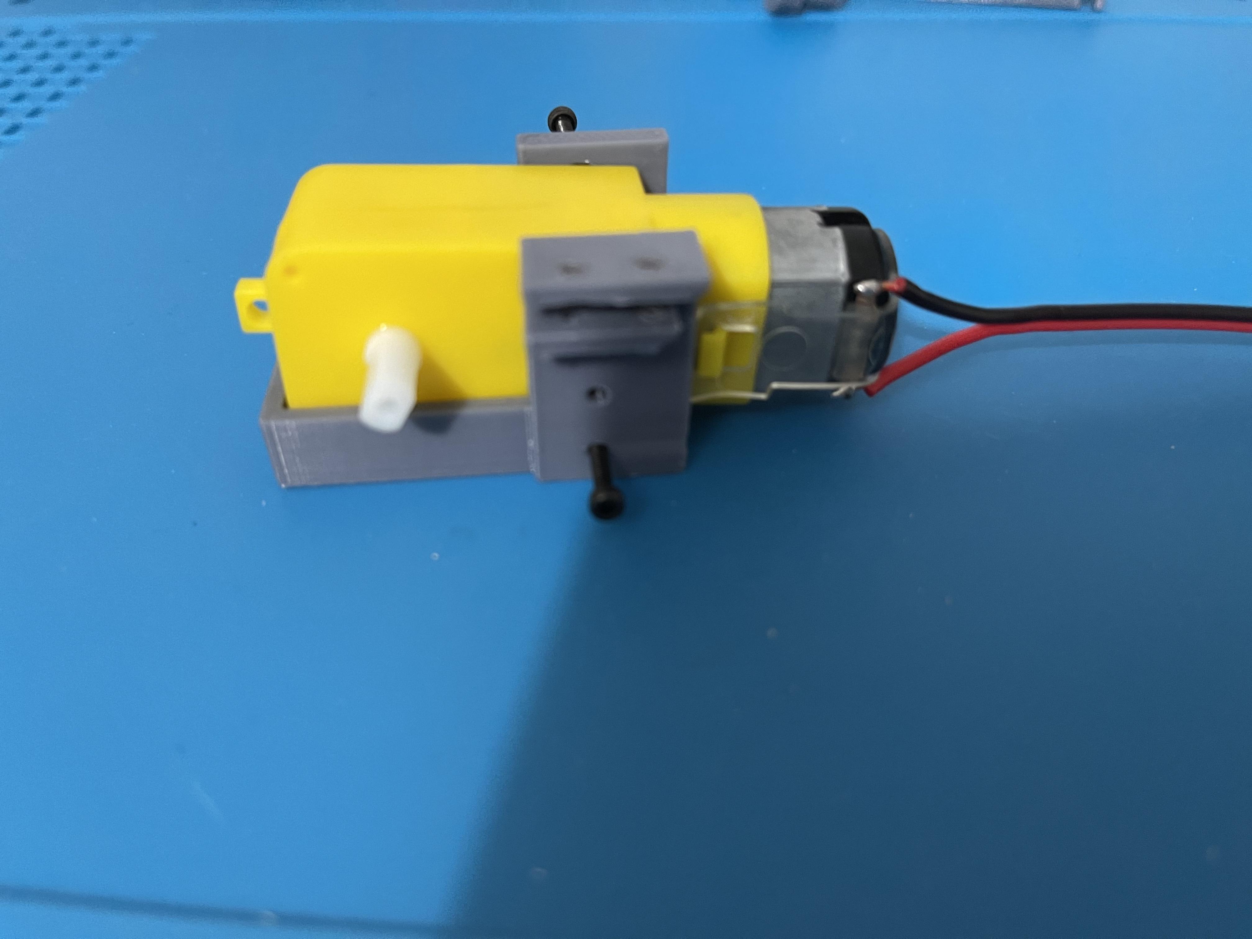
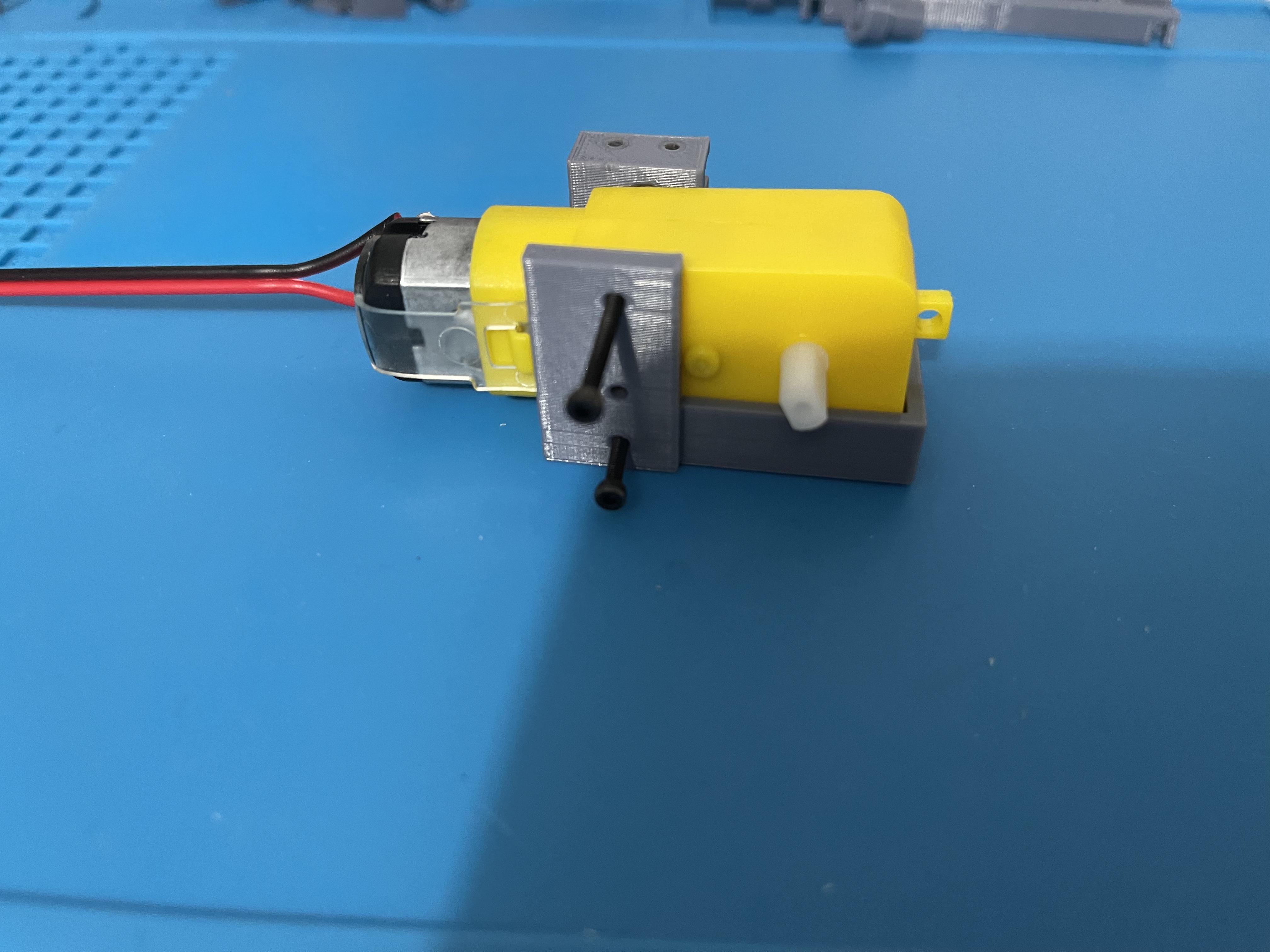
Attach the dc motors to their mounts as shown in the images. You'll need 2 pcs of 10 mm hex-head M2 screws, and 1 pc of 20 mm hex-head M2 screw.
Note: Wires need to be pre-soldered to the motor before attaching it to the mount. Some motors do come with pre-soldered wires, while others come with the wires unsoldered or no wires at all. I recommend using 22 AWG red and black coated wires, and soldering them uniformly; eg: Red on the left motor terminal, Black on the right motor terminal.
Attach the Motors to the Rover Base
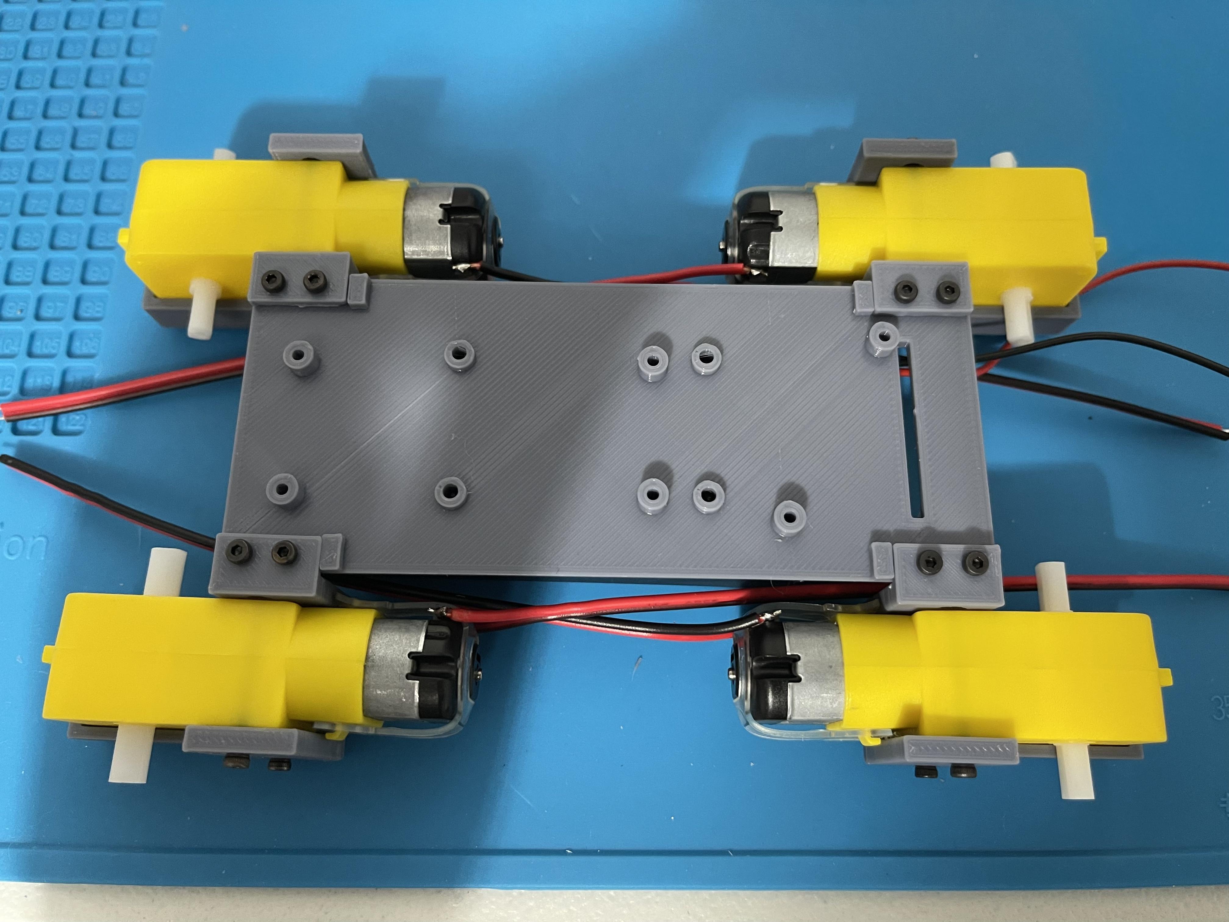
Attach the four DC motors to the rover base. Use 8 mm hex-head screws to fasten them (total of 8 needed).
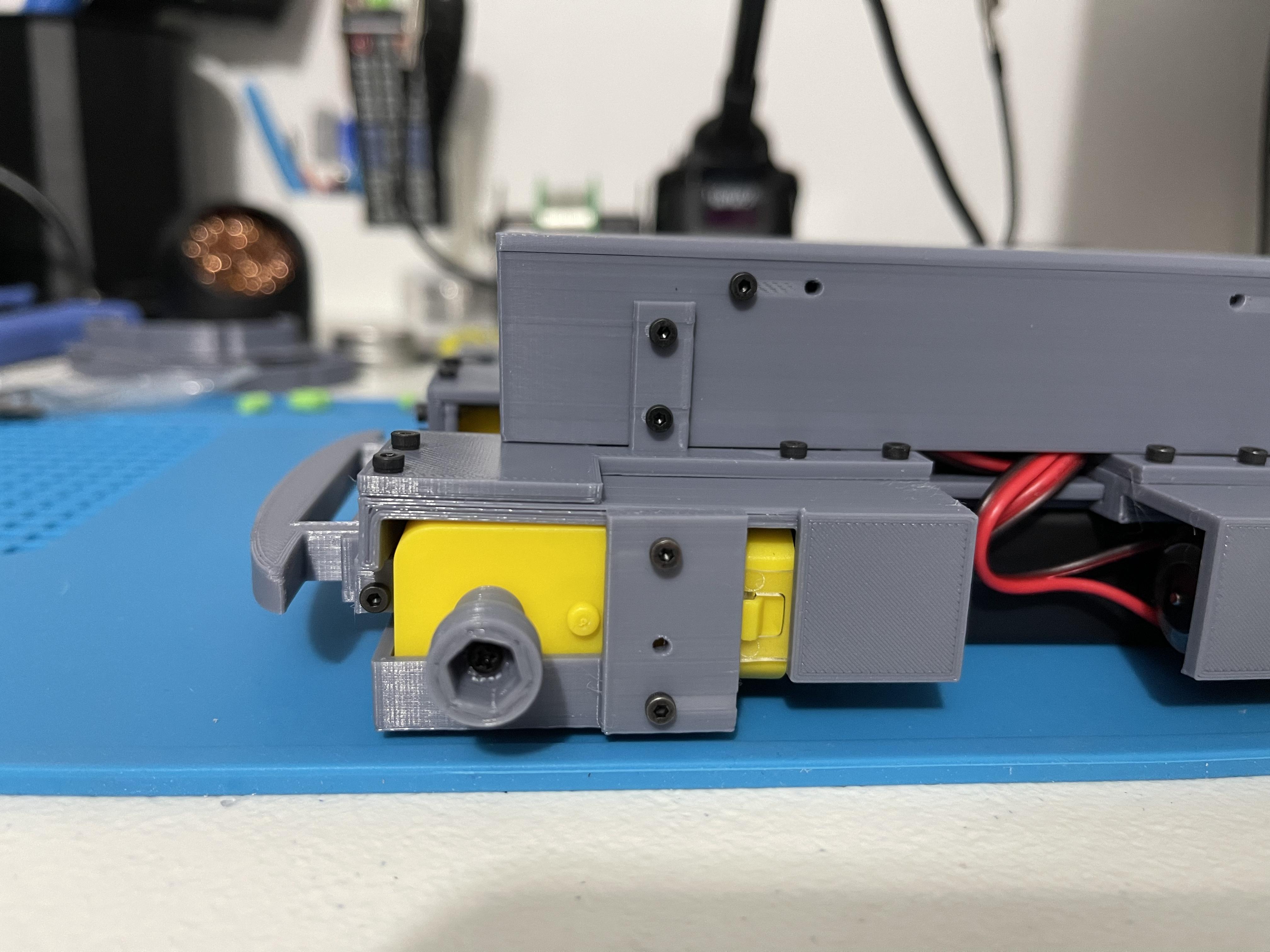
Attach the Bumpers
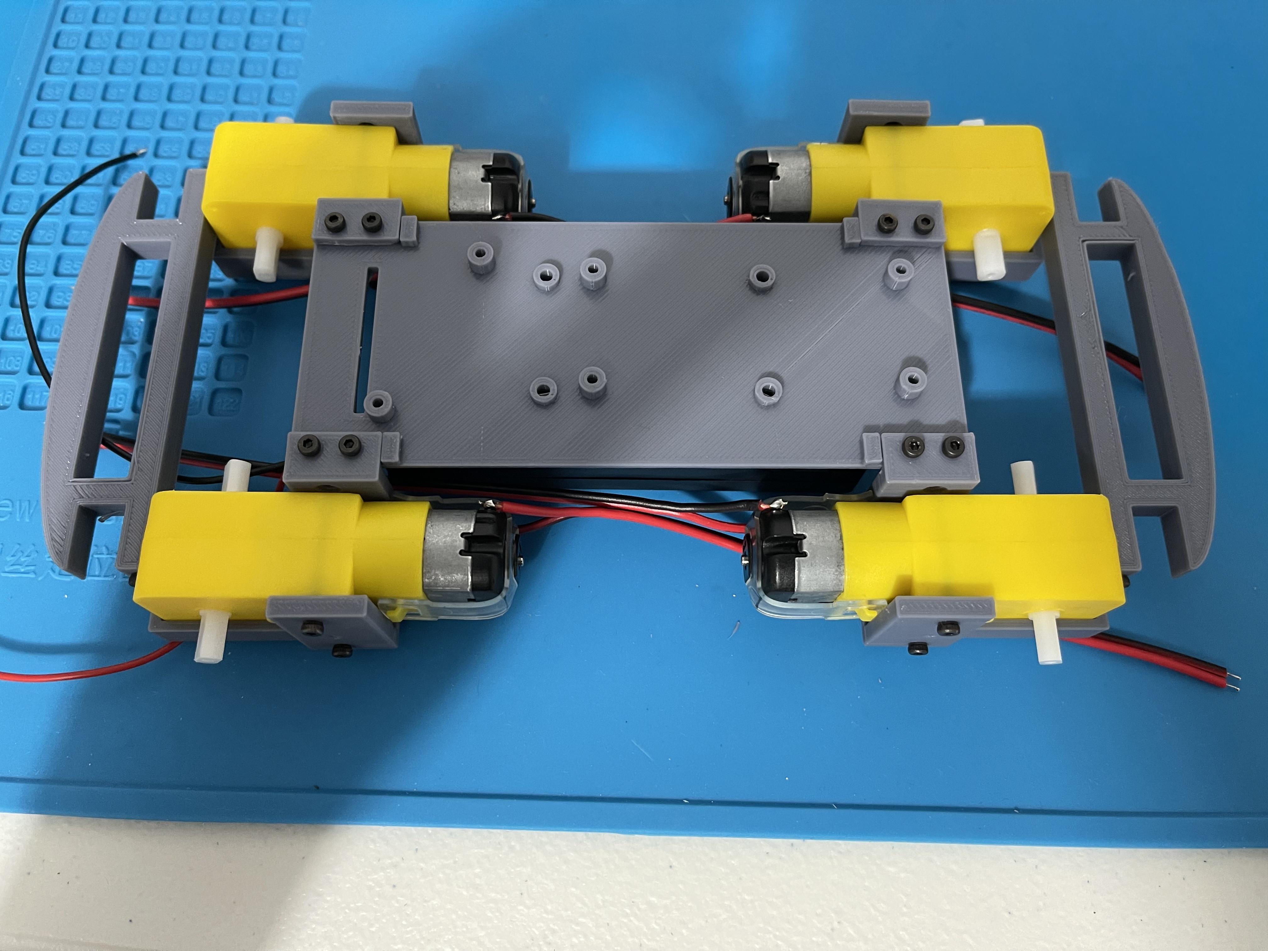
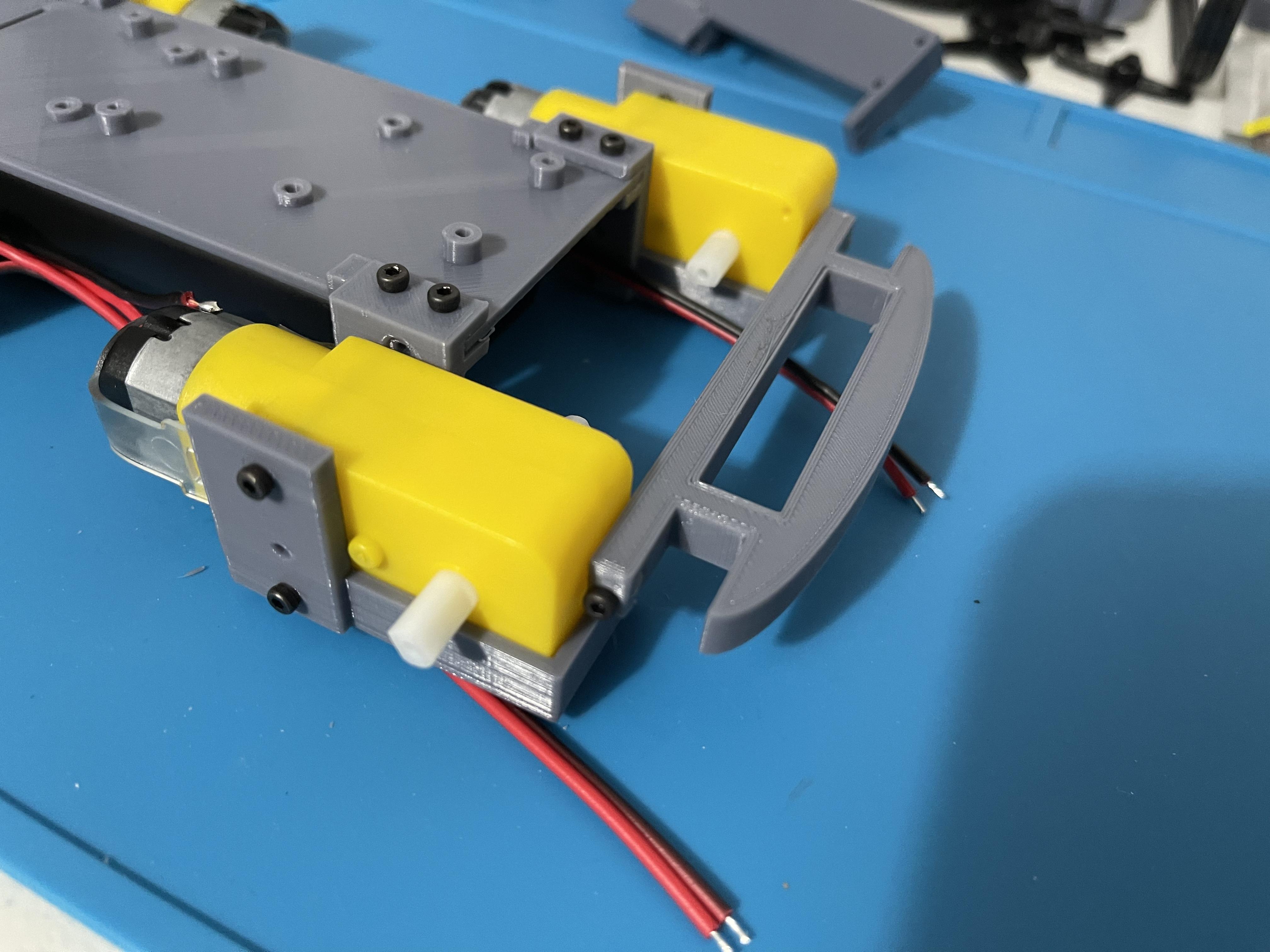
Use 8mm hex-head screws. Total of 4 needed (one on each side of the bumper).
Attach the Motor Cover and Support
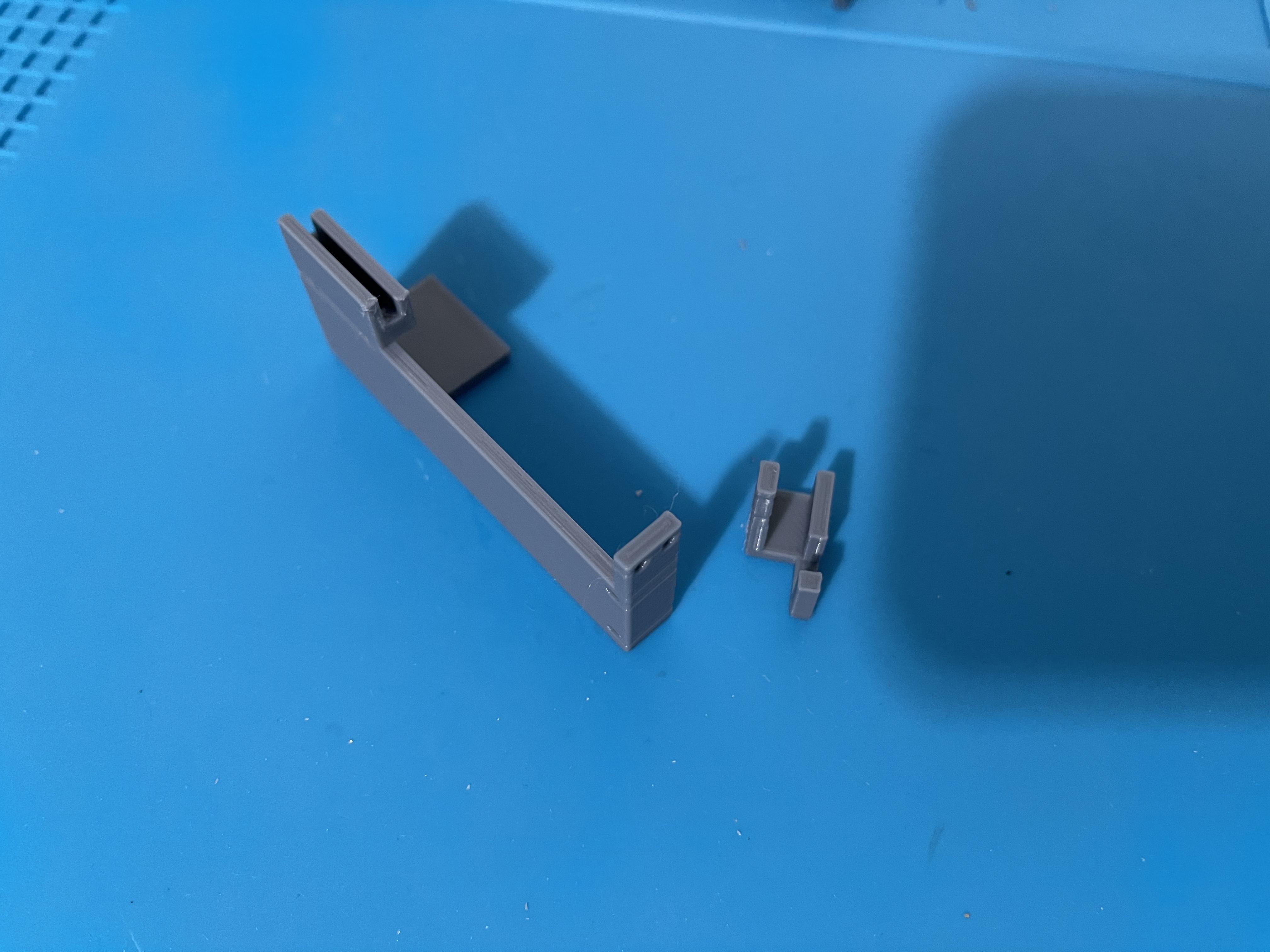
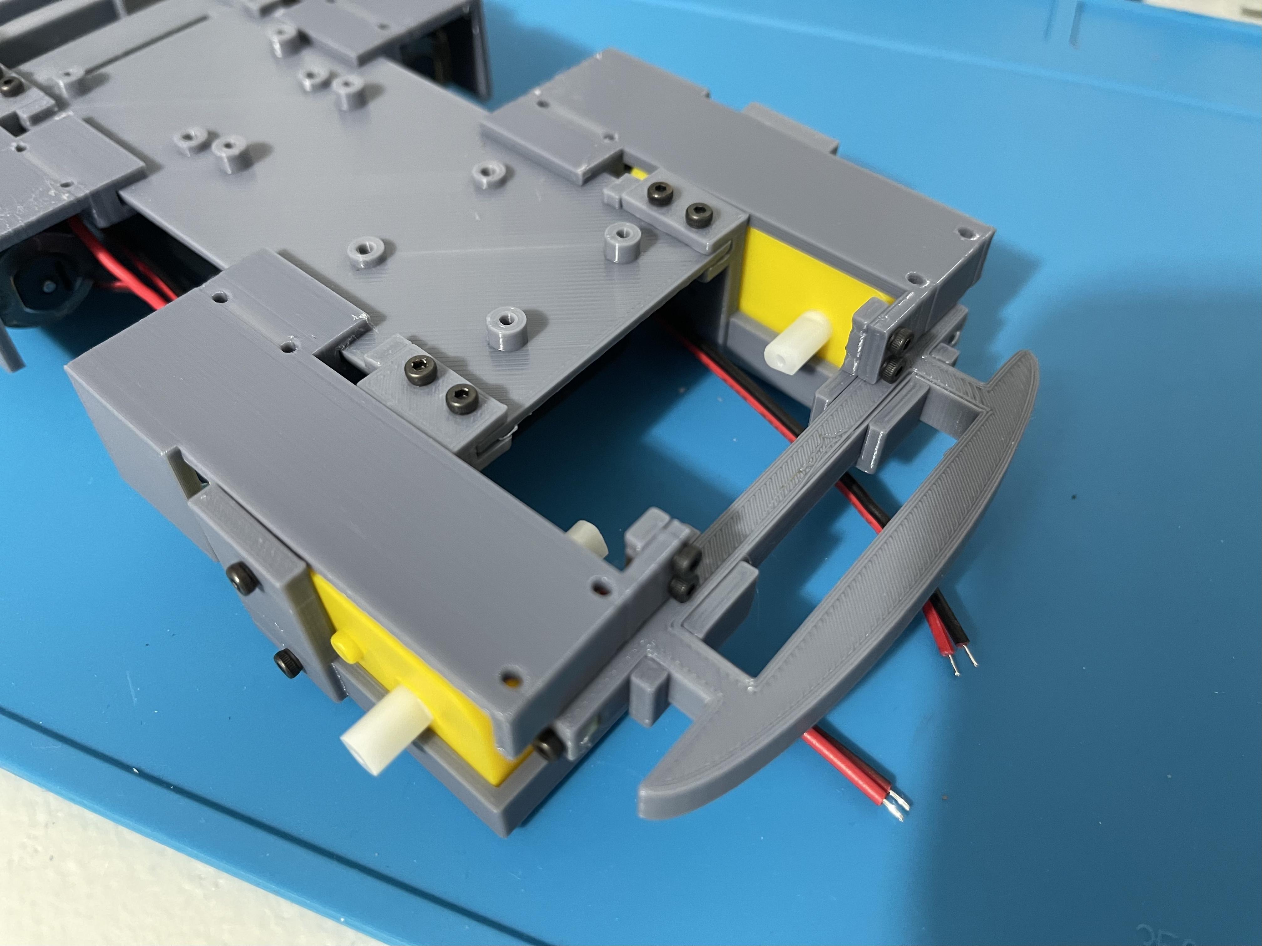
The motor cover has a slide-on section, similar to the motor mount, that attaches to the rover base and is held in place with the help of the support piece and two 6 mm hex-head screws.
Prepare the Pi Zero (Install the Headers)
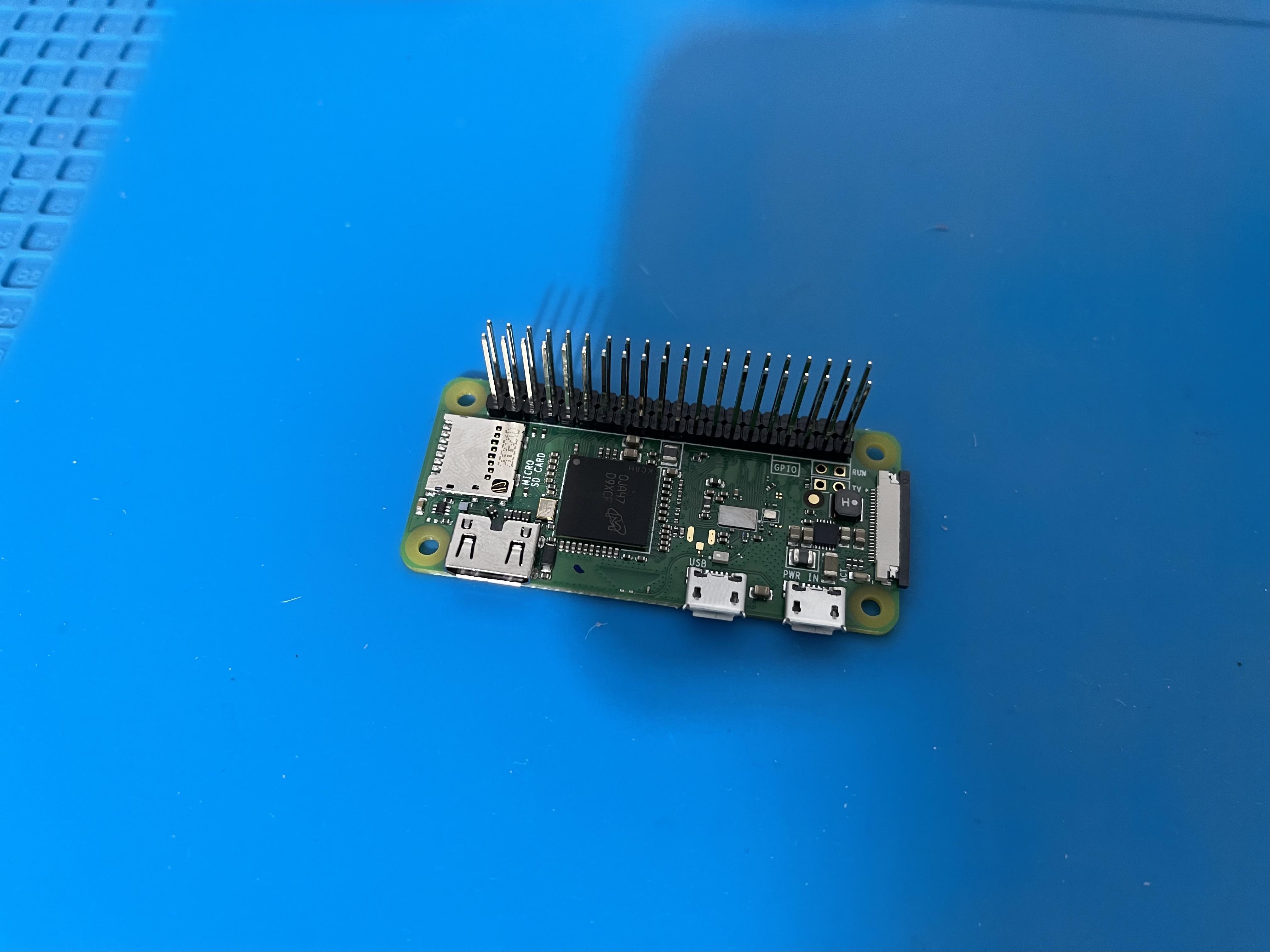
Install (solder) the 21mm long headers on the Pi Zero. The headers may come in a single 40-pin array; so just cut it in half to make 2 x 20.
Note: The 21 mm long headers are necessary for pinout extension when the motor controller is installed on top of the Pi 0. This allows access to unused pins on the Pi 0 to add other peripherals or hats in the future.
Prepare the Pi Zero (Install the Necessary Software)
Note: It's recommend that your Pi Zero has the latest Raspbian installed/initiated and also connected to your local WiFi before proceeding below. You can also run the NOOBS imager to get a clean but latest version of Raspbian.
- Login to your Pi Zero as a superuser (default username is "pi", password is "raspberry")
- If you have not done so or think your Pi needs to upgrade, type: sudo apt-get update then: sudo apt-get upgrade
- Type: sudo raspi-config and go to interface options to enable the Camera interface, SPI, I2C, SSH and Remote-GPIO
- Install Adaruit's Motorkit library and its dependencies by typing: sudo pip3 install adafruit-circuitpython-motorkit
- Install Approximate Engineering - Input library by typing: sudo pip3 install approxeng.input
Pair a Bluetooth Game Controller to the Pi Zero
Note: It's recommended to use a PS4 or Xbox (One) controller. The input library supports a variety of game controllers but it's also possible that some controllers may not be supported. For full details on the input library (credit to Tom Oinn) or how to add support for a new controller, click here.
- On the Pi type: sudo nano /etc/modprobe.d/bluetooth.conf
- Enter the following on the file being created: options bluetooth disable_ertm=1 save then exit
- Reboot the pi by typing: sudo reboot
- After reboot, on the Pi type: bluetoothctl to enter the bluetooth shell.
- In the bluetooth shell enter the following: agent on then enter: default-agent
- Type: scan on to enter bluetooth pairing mode and scan for nearby devices
- Put the game controller into pairing mode. After a few seconds, the MAC address of the game controller should show up in the scan.
- Note down the MAC address of the game controller, eg: C8:3F:26:1D:A3:77
- Pair with the game controller by typing: pair [your controller's MAC address], eg: pair C8:3F:26:1D:A3:77, in the bluetooth shell. If successful the following message will show up: Pairing successful
- The Pi will also try to automatically connect to the game controller. On the bluetooth shell, the following message will show up if successful: Connection successful. If not, try to manually connect with the controller by typing: connect [your controller's MAC address], eg: connect C8:3F:26:1D:A3:77
- Tell the bluetooth driver to trust your controller by typing: trust [your controller's MAC address], eg: trust C8:3F:26:1D:A3:77
- Exit the bluetooth shell by using CTRL+D or by typing quit
- The game controller should now automatically connect with the Pi every time it's turned on.
Mount the Pi Zero on the Rover Base
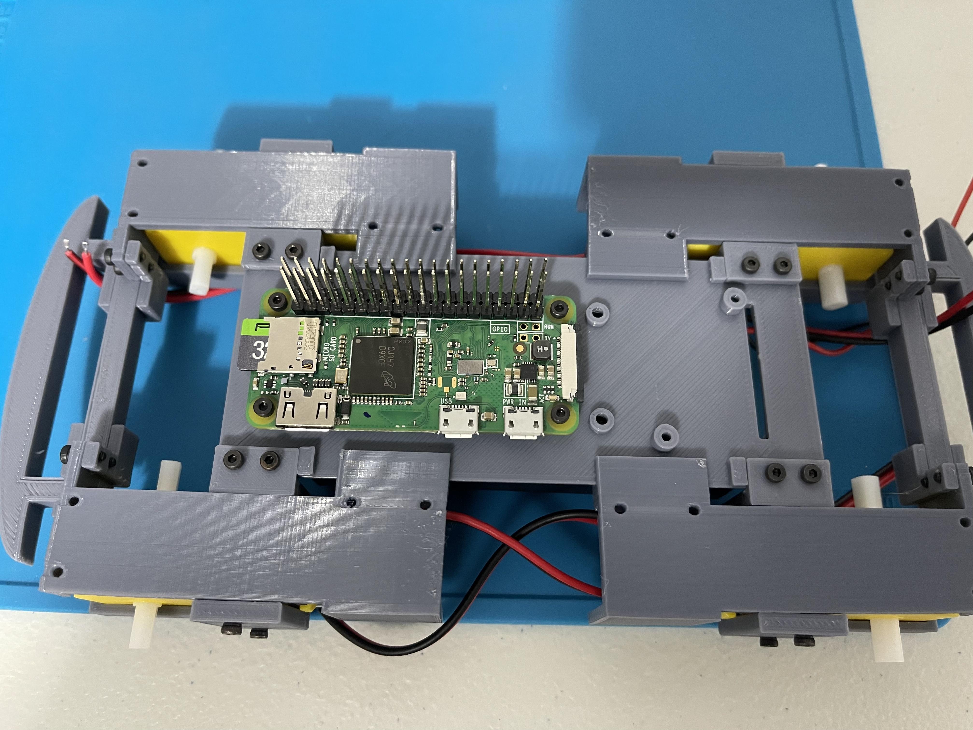
Use 4mm hex-head M2 screws.
Connect the Pi Camera Ribbon Cable
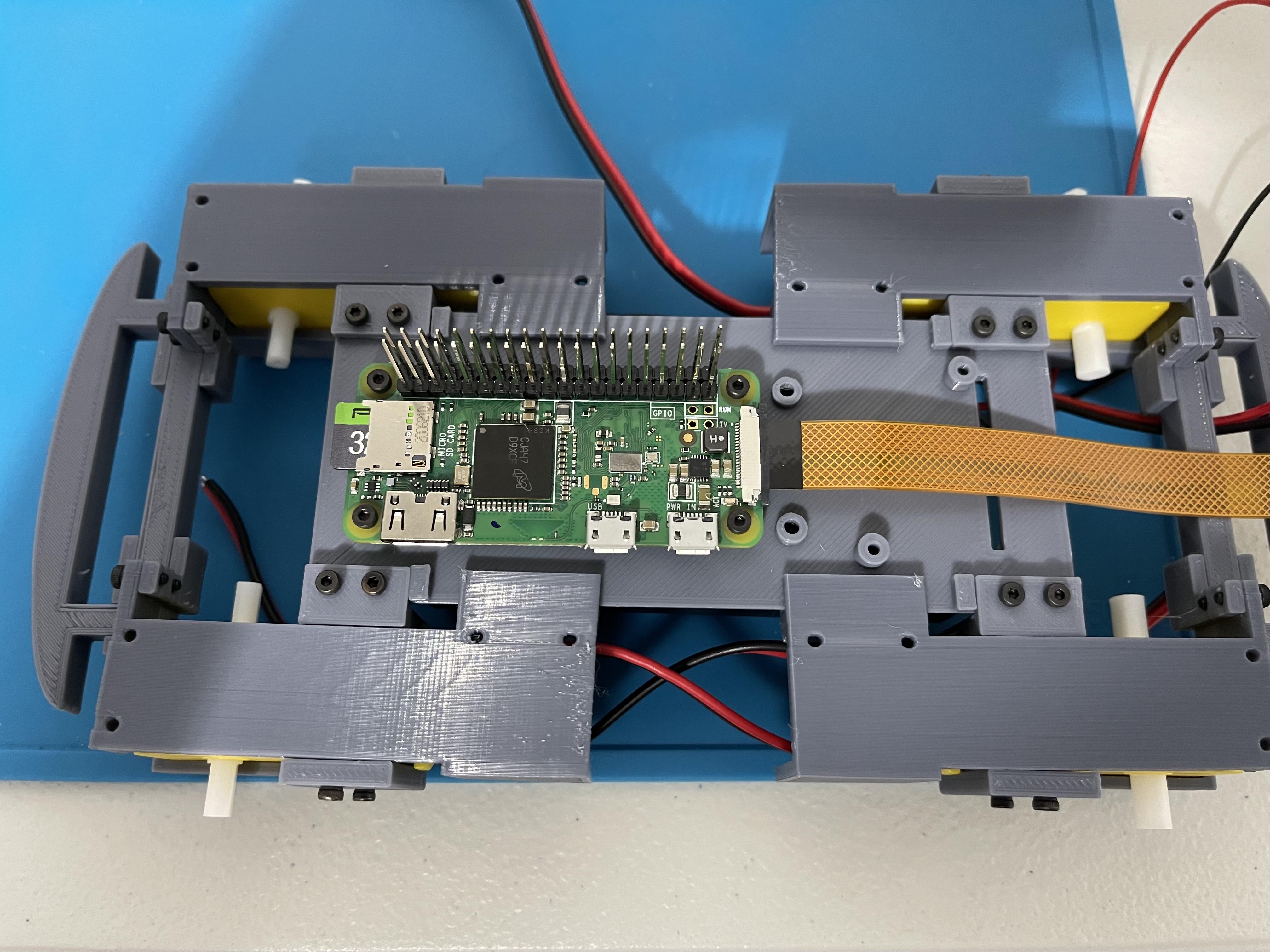
Contacts on the ribbon cable must be facing down when inserted to the camera interface terminal of the Pi Zero.
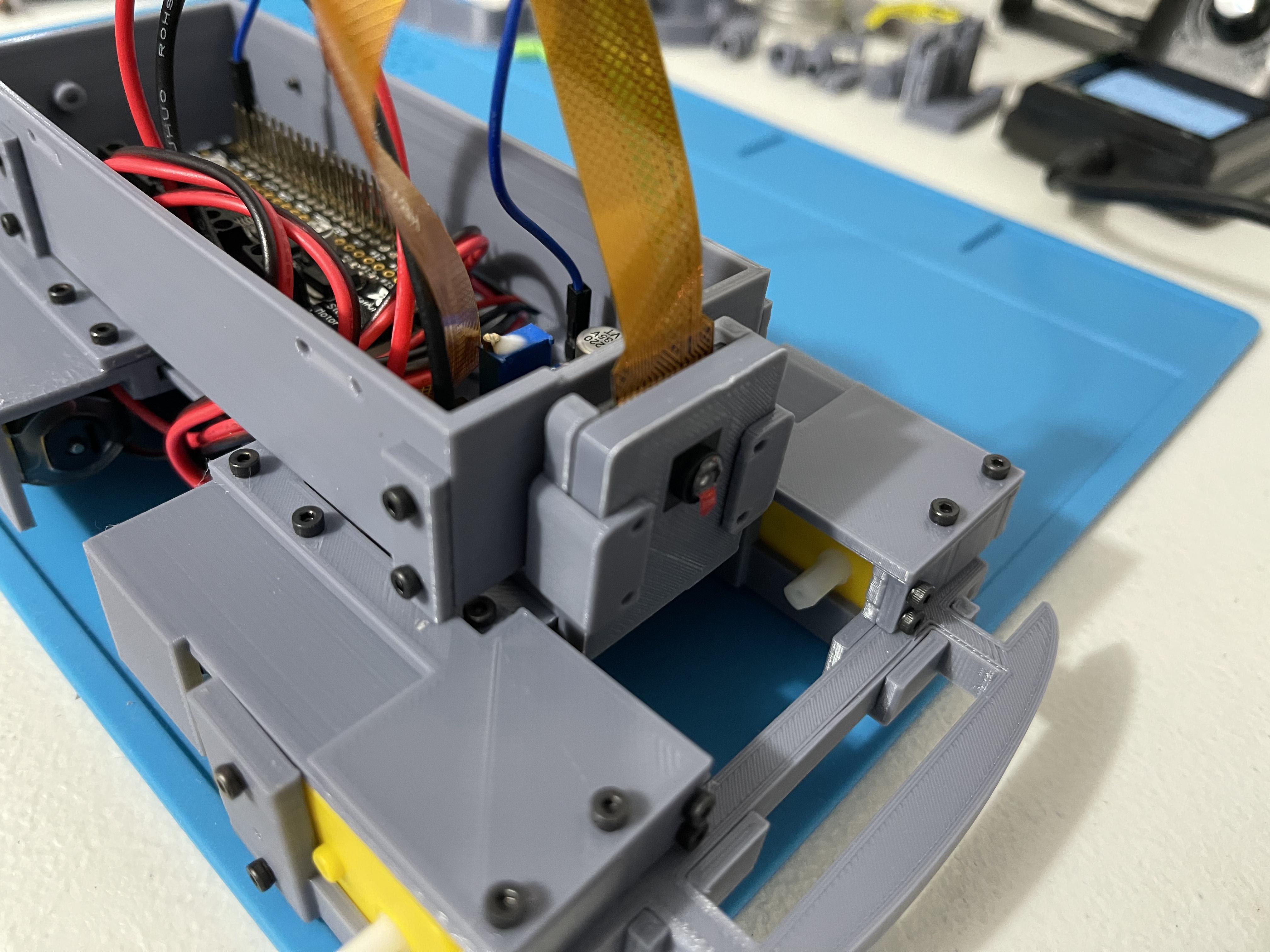
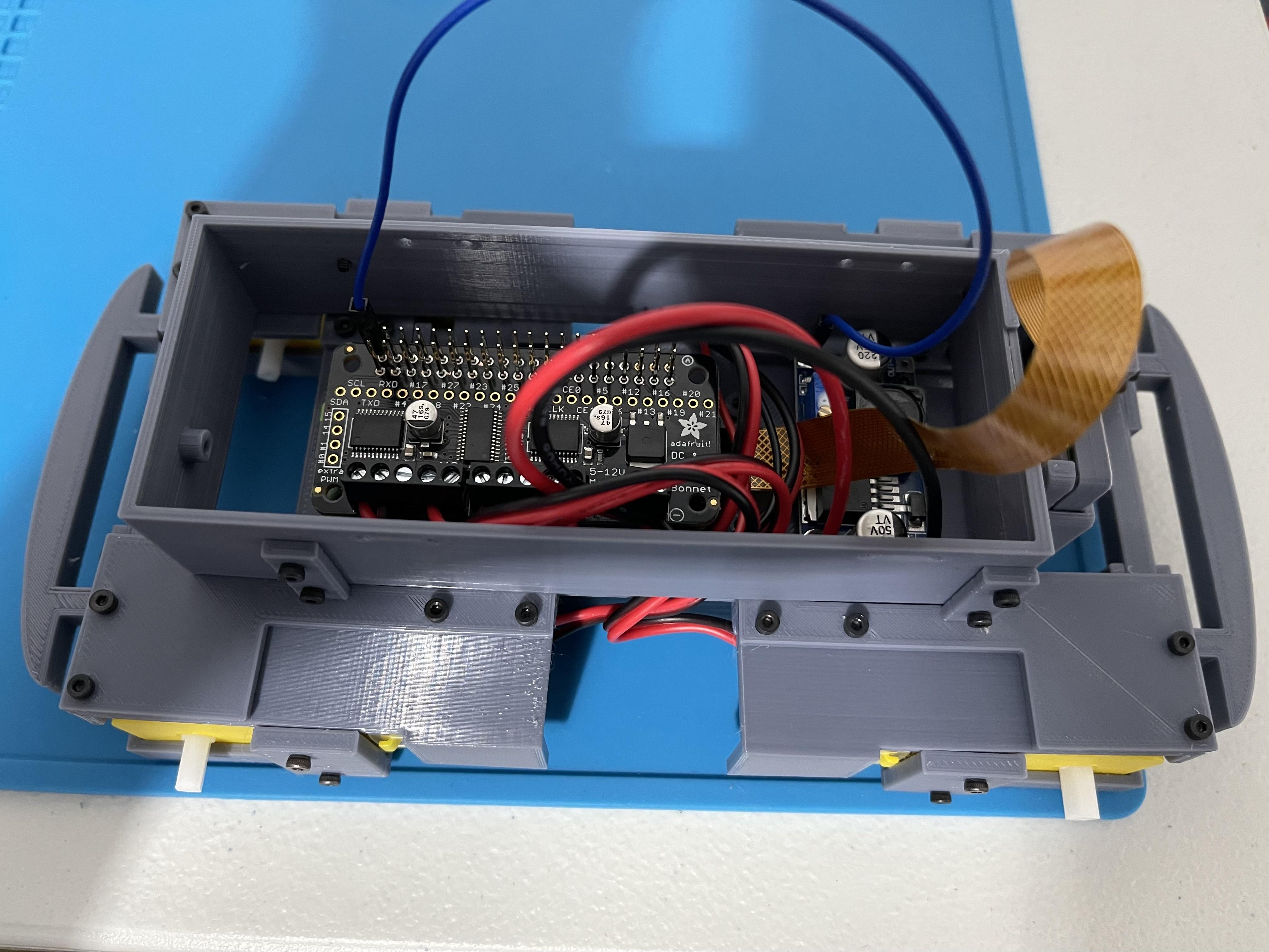
Install the DC Motor Controller
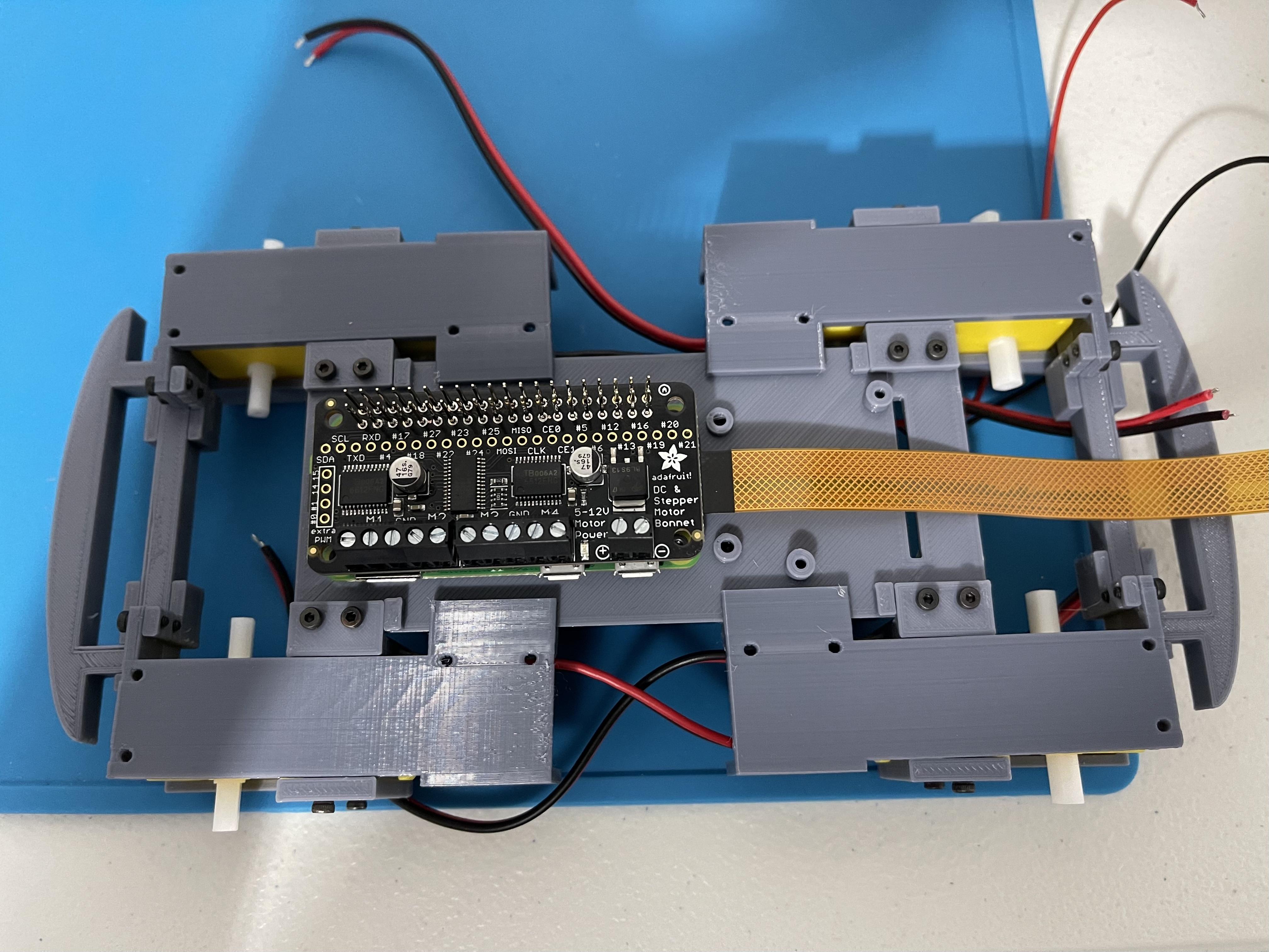
Push the DC Motor Controller all the way down until the pin headers on the Pi Zero are protruding enough to allow another bonnet/hat to be stacked.
Connect the Motors to the Controller Terminals
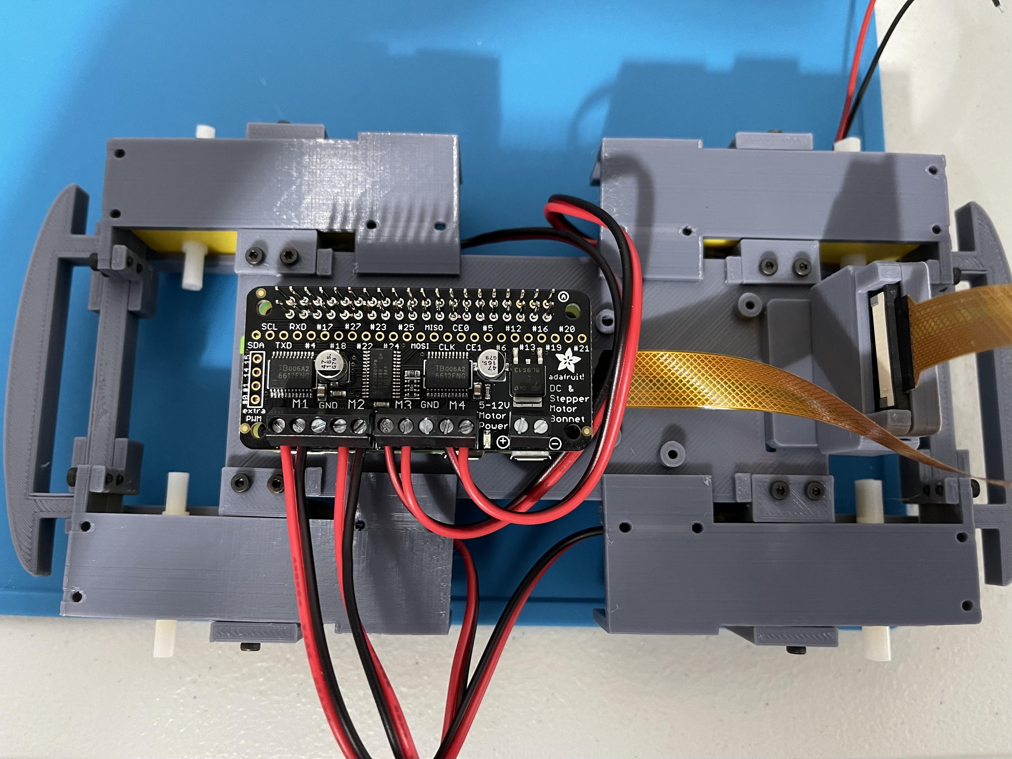
Note: It is recommended that motor wires are soldered following a uniform pattern for each motor. This way it's easier to manage the control/movement of the rover later on. In this guide, the red wire is attached to the left motor terminal and the black wire is to the right motor terminal, when the motor terminals are facing you.
On the image, the motors are connected to the controller in the following order:
- M1 to the Bottom Left Motor, Red Wire then Black Wire
- M2 to the Bottom Right Motor, Red Wire then Black Wire
- M3 to the Top Left Motor, Black Wire then Red Wire
- M4 to the Top Right Motor, Black Wire then Red Wire
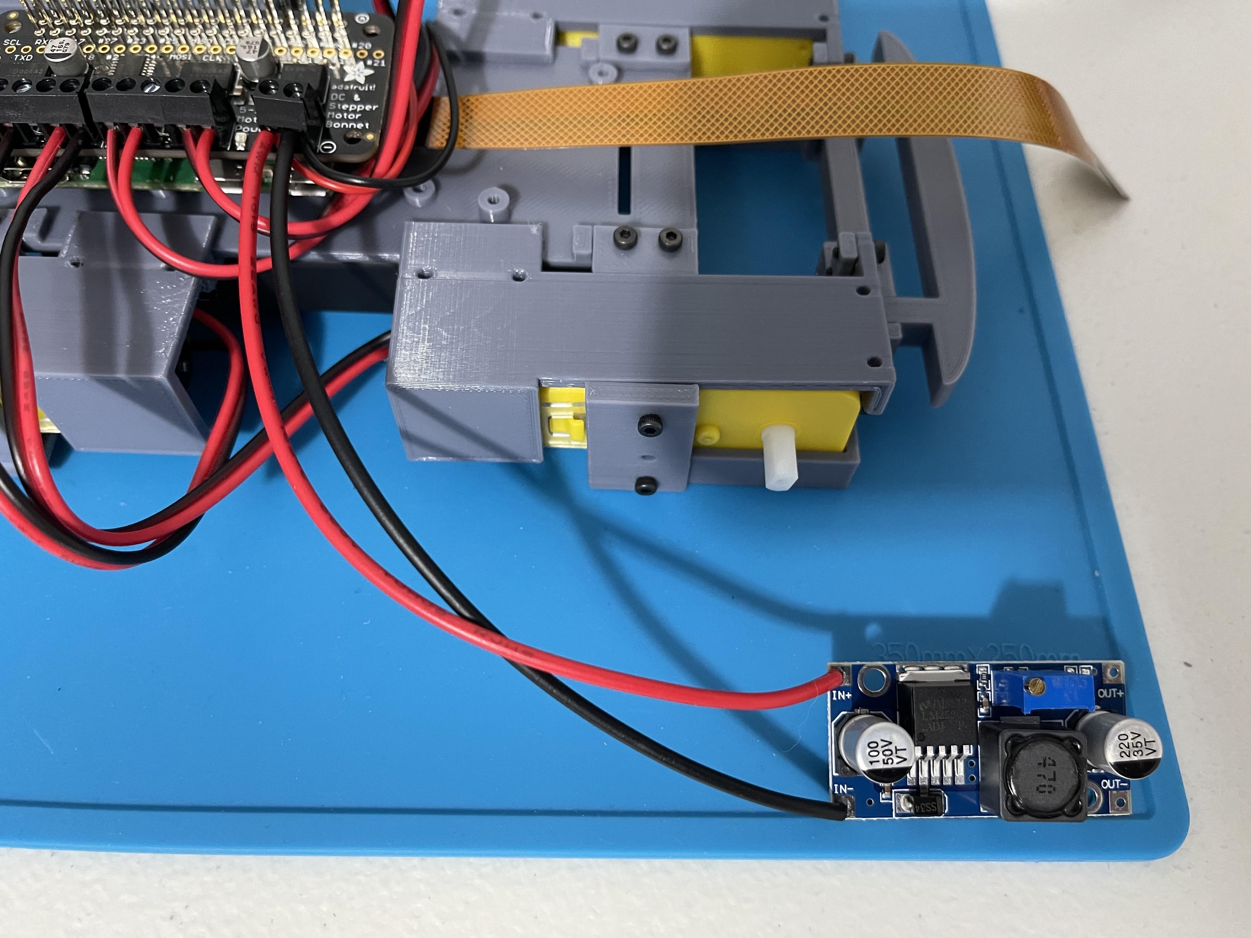
Adjusting and Installing the DC Buck Converter
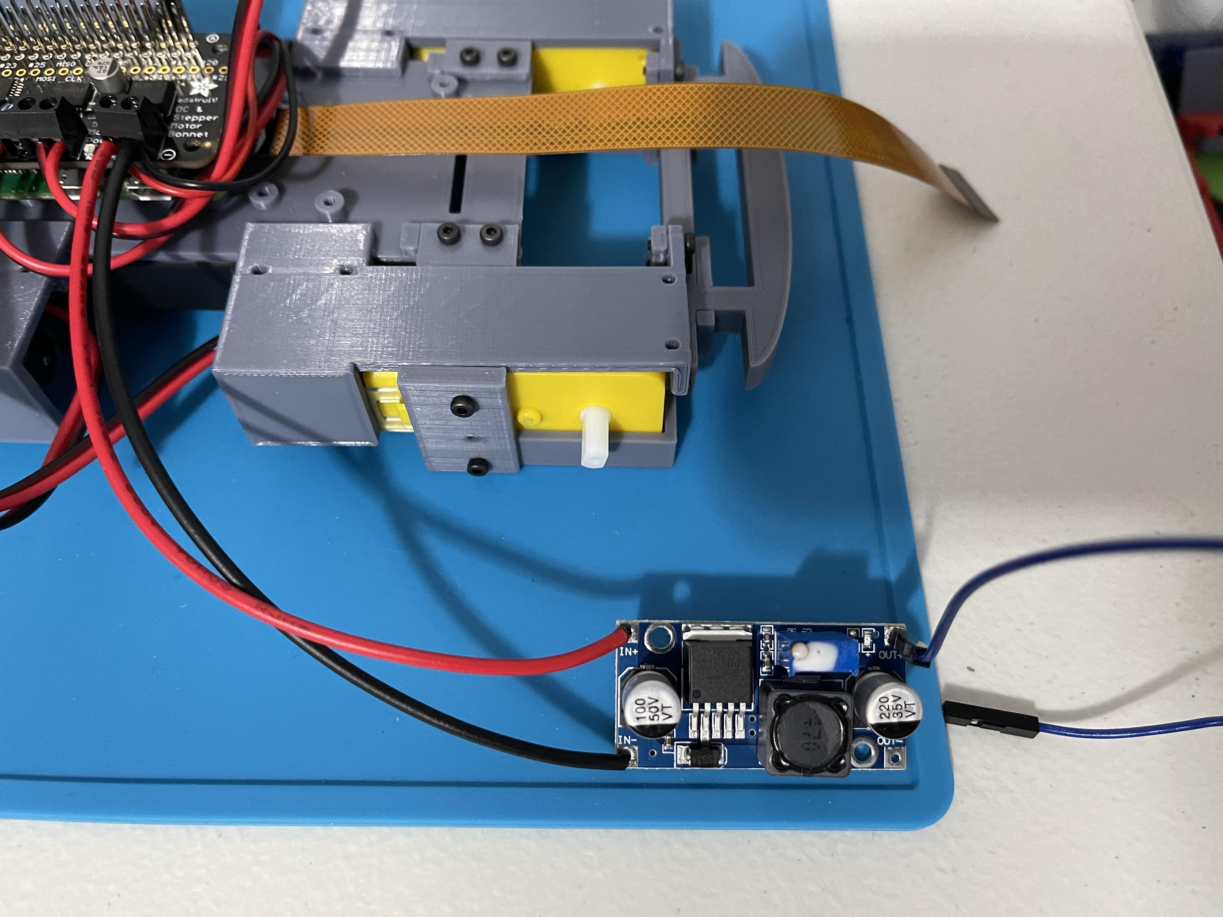
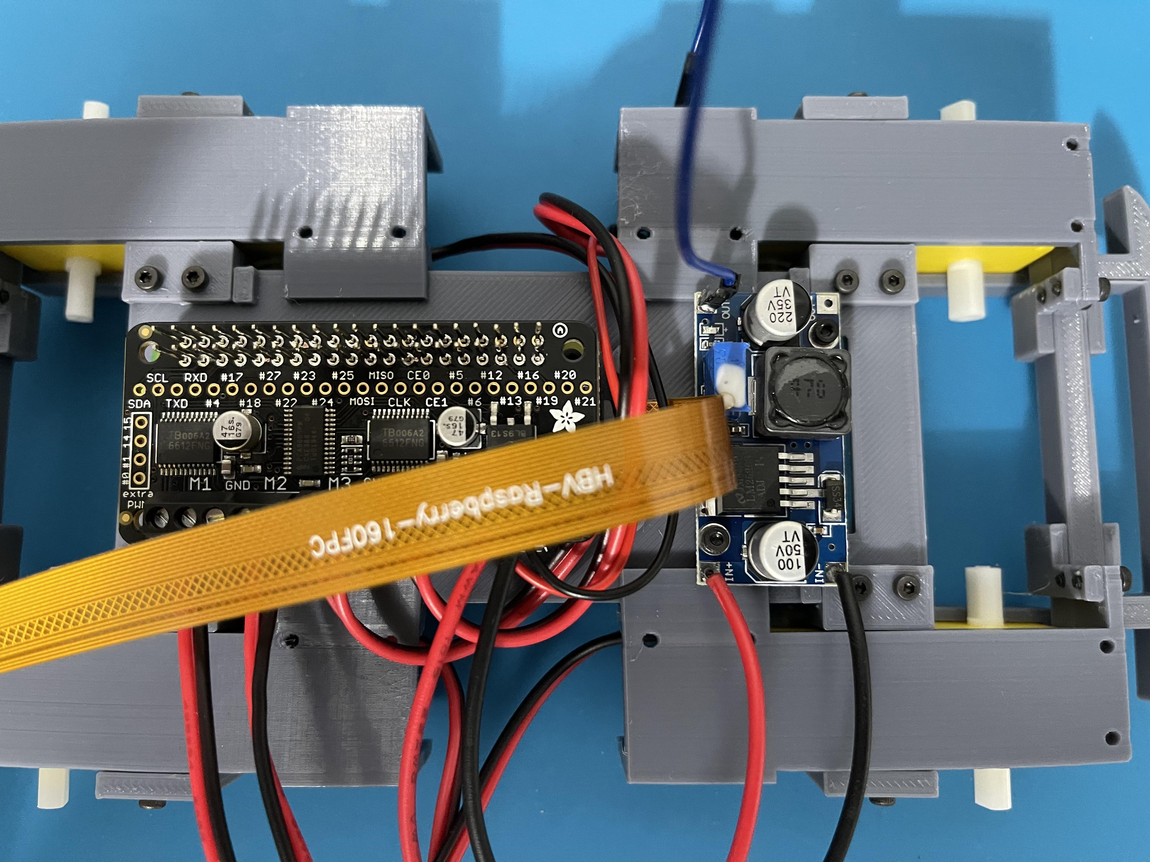
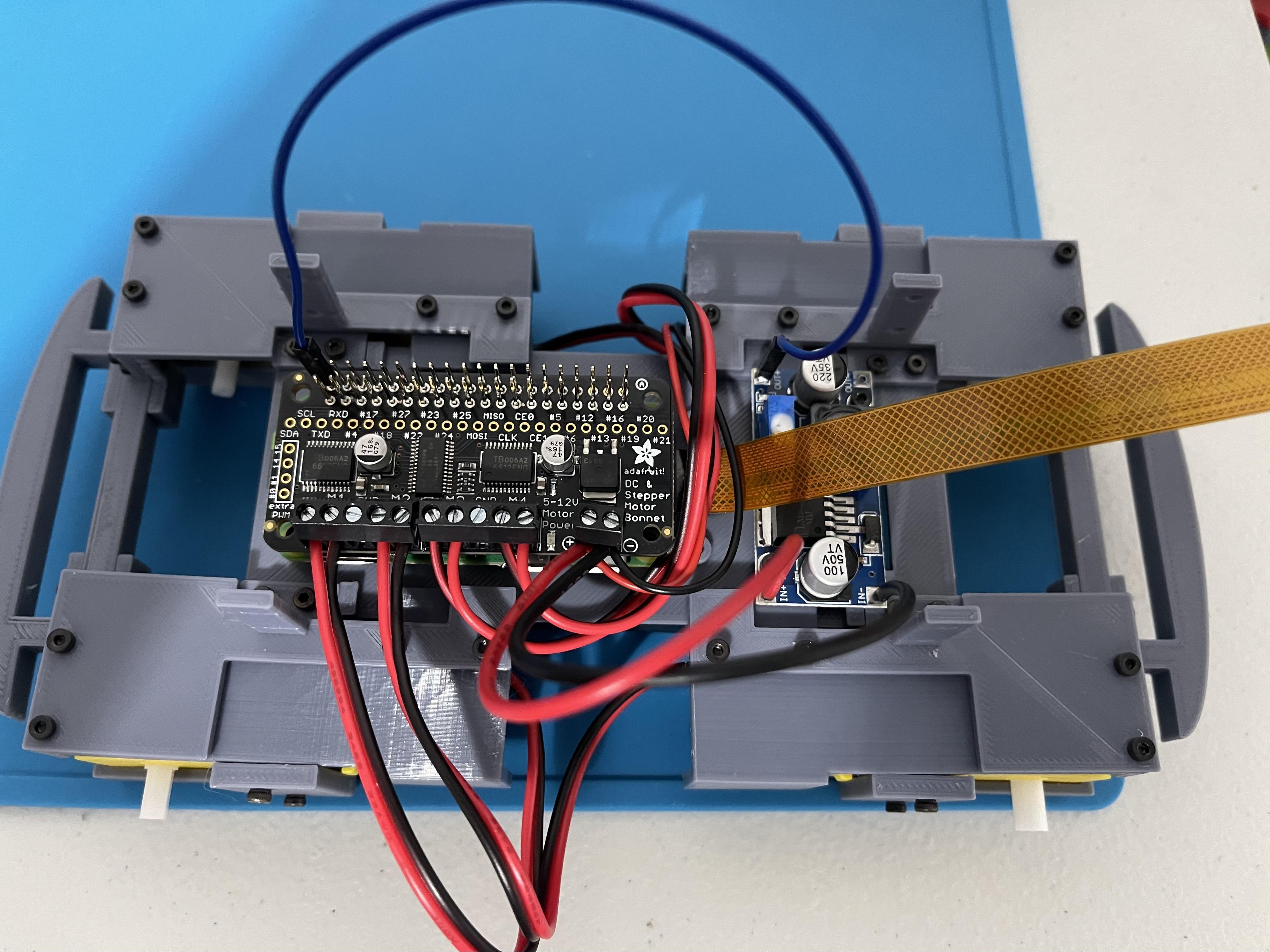
- Solder two wires (red and black, 4 to 5 inches in length) to the + and - input terminals of the dc buck converter.
- Connect the + and - wires of the battery holder to the + and - (power) terminals of the Motor Controller.
- Also, connect the + and - input of the buck converted to the + and - (power) terminals of the Motor Controller. (What's happening is the voltage from the battery will be used to supply voltage to both the motor controller and as well as the buck converter)
- Using a multi-meter, check the power terminal of the motor controller for any short. If things are connected correctly, the multi-meter should "not" buzz.
- Install two fully charged 18650 batteries in the battery holder and move its on/off switch to "on"
- The LED on both the motor controller and the buck converter should light up.
- Adjust the trim pot on the buck converter and measure the voltage on the output terminals until it reaches approximately 5v. (Rotate clockwise to increase voltage and counter-clockwise to decrease)
- Once the output of the buck converter is adjusted to 5v, add a drop of easy-to-remove glue (general purpose or hot glue are just fine) on the trim pot to prevent it from moving and accidentally changing the output voltage.
- Solder the Male side of a Male to Female Dupont-type wire to the + Output terminal of the buck converter.
- Mount the Buck Converter to the rover base with the use of 2 pcs 4mm hex-head M2 screws.
- Connect the Output of the buck converter to one of the 5v input pins of the Pi Zero.
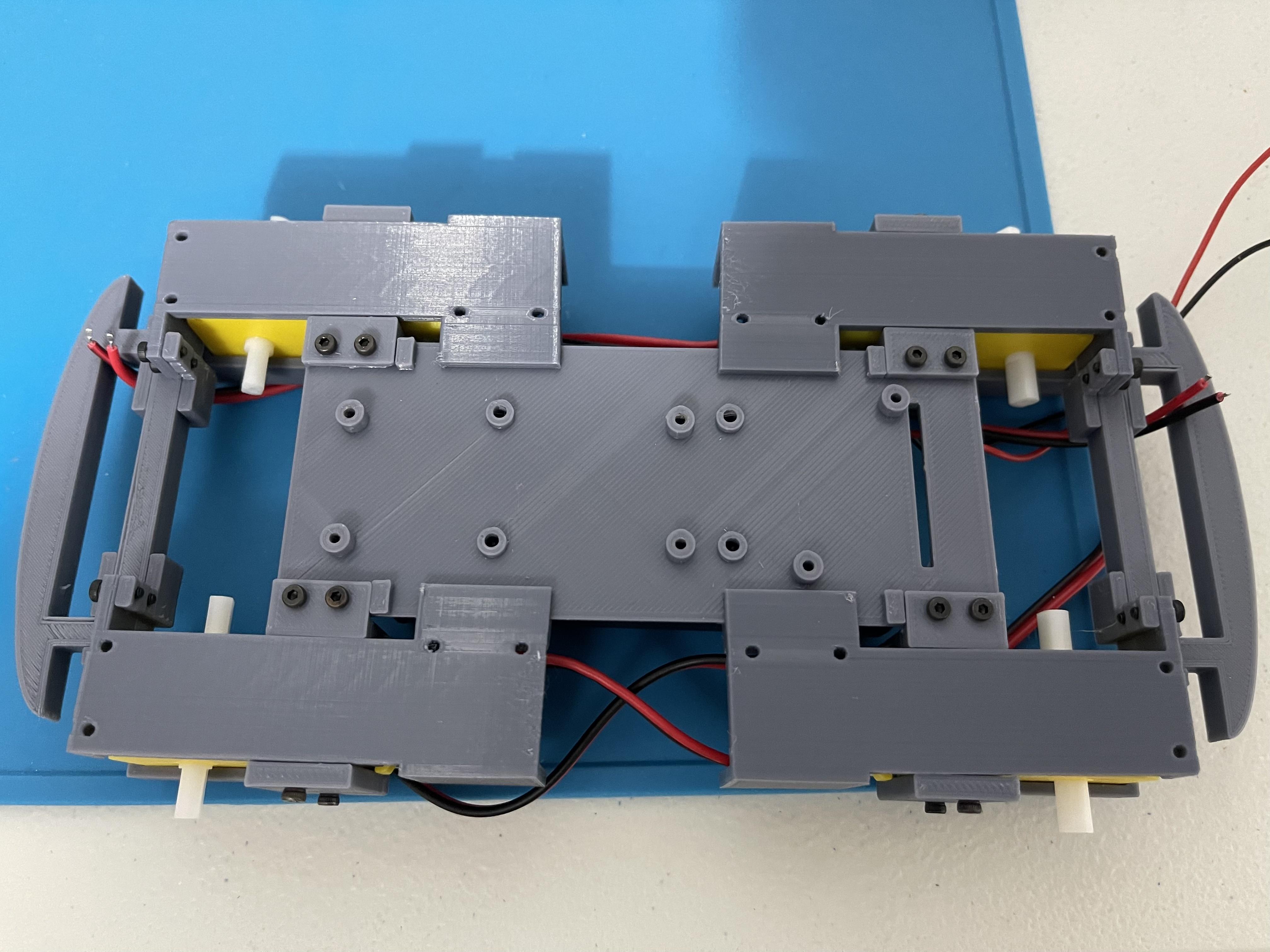
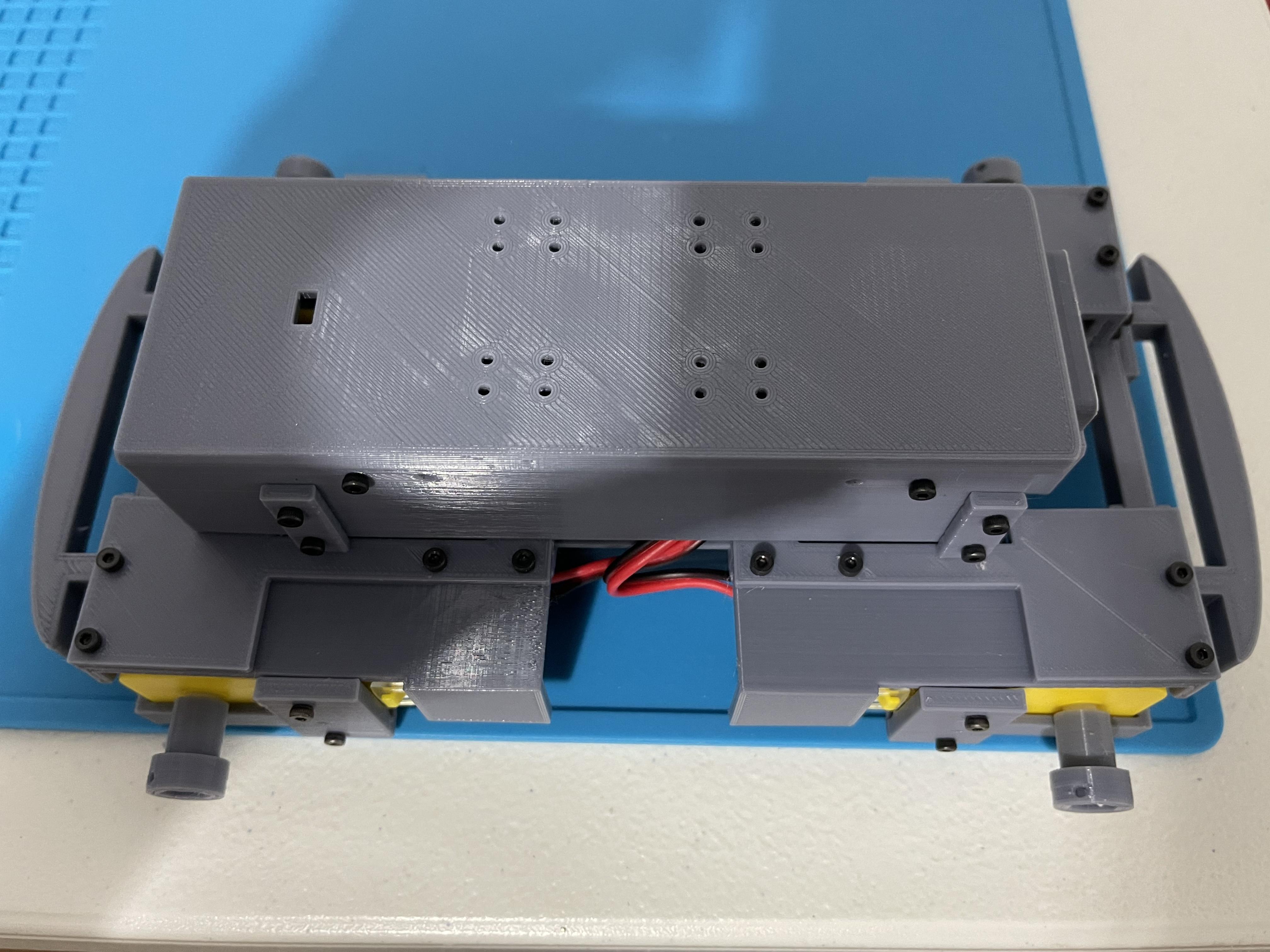
- Install the four Chassis Brackets (two pairs of Chassis Bracket A and B) using 16 pcs 4mm hex-head M2 screws.
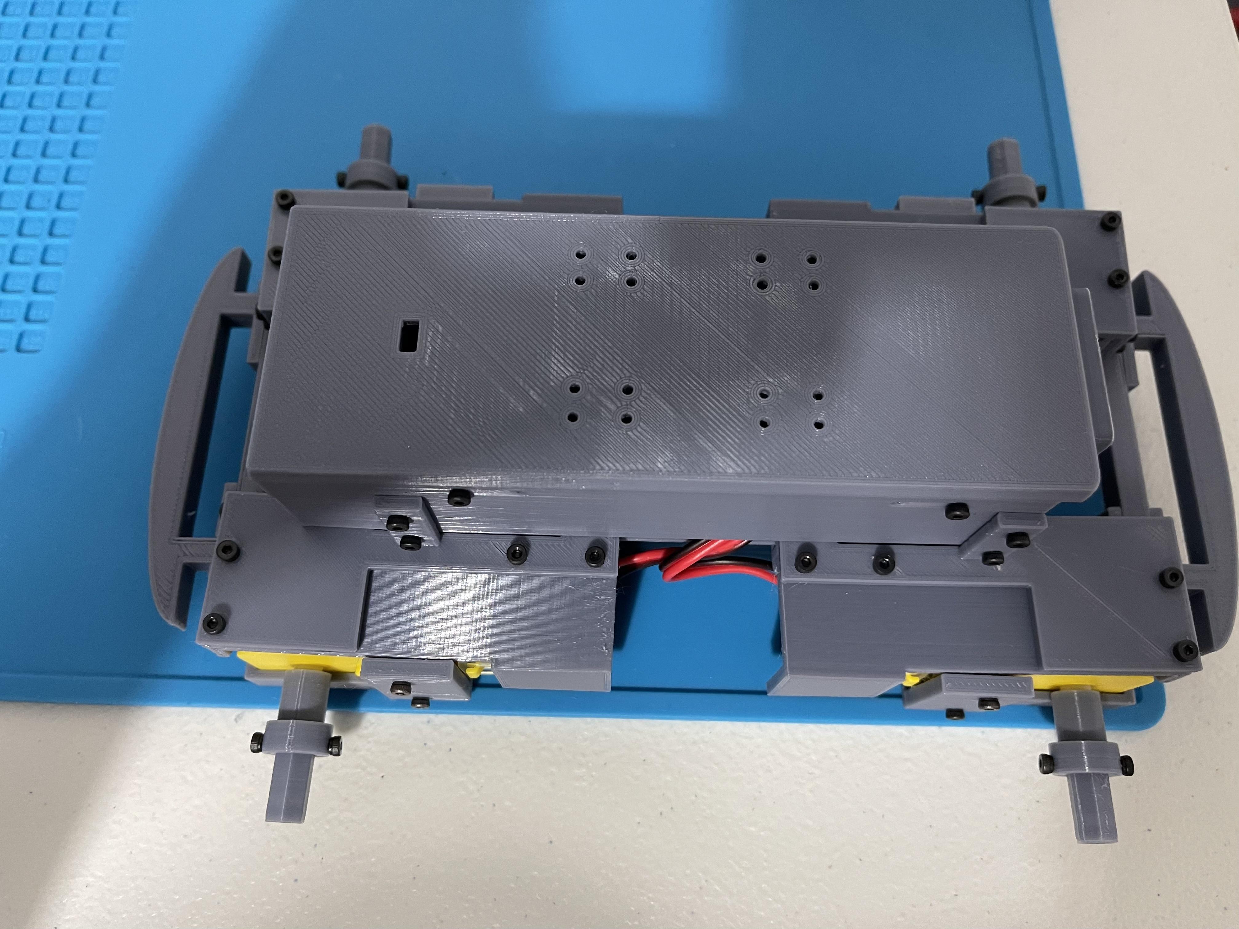
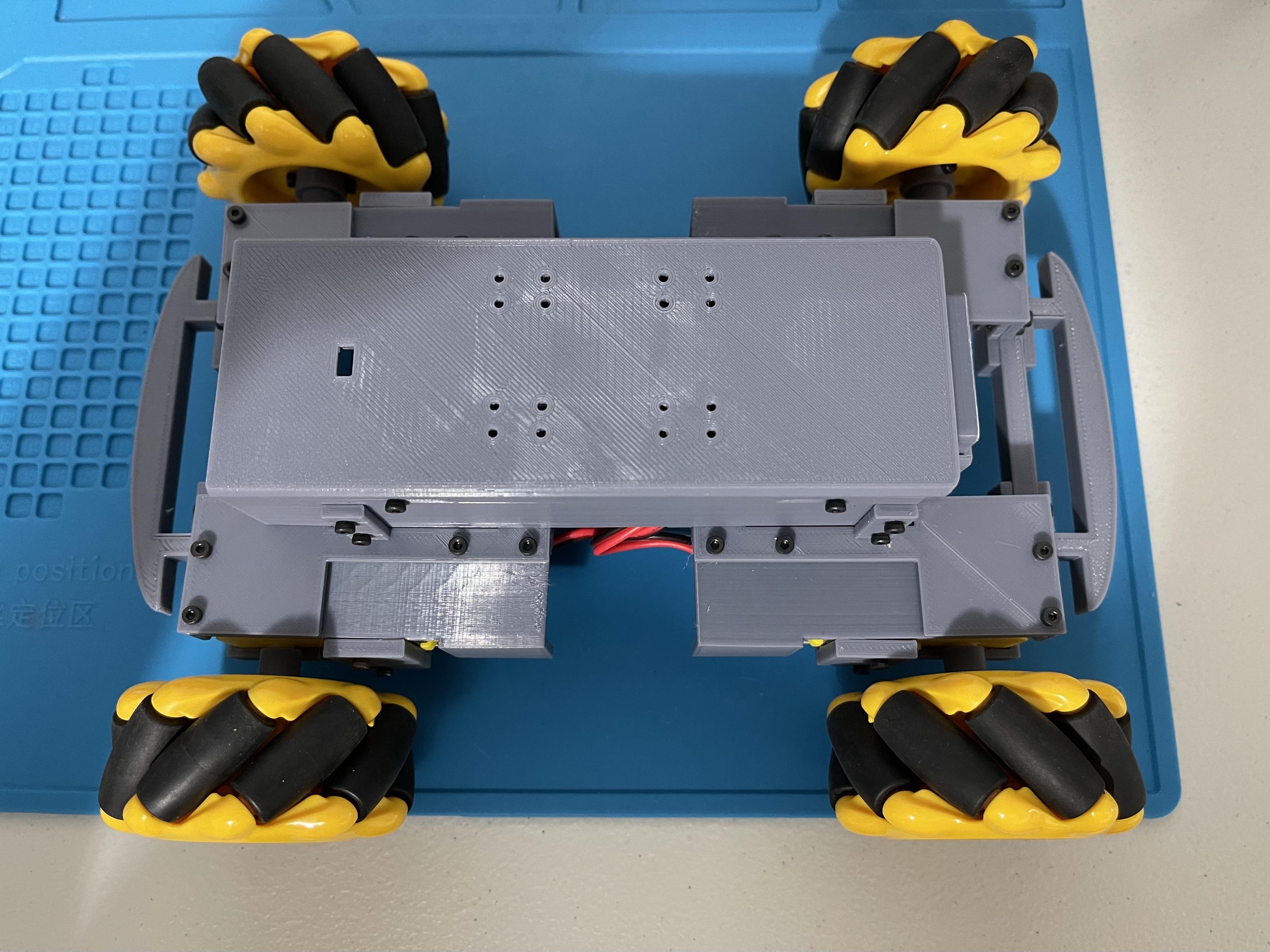
Install the Chassis (Cover)
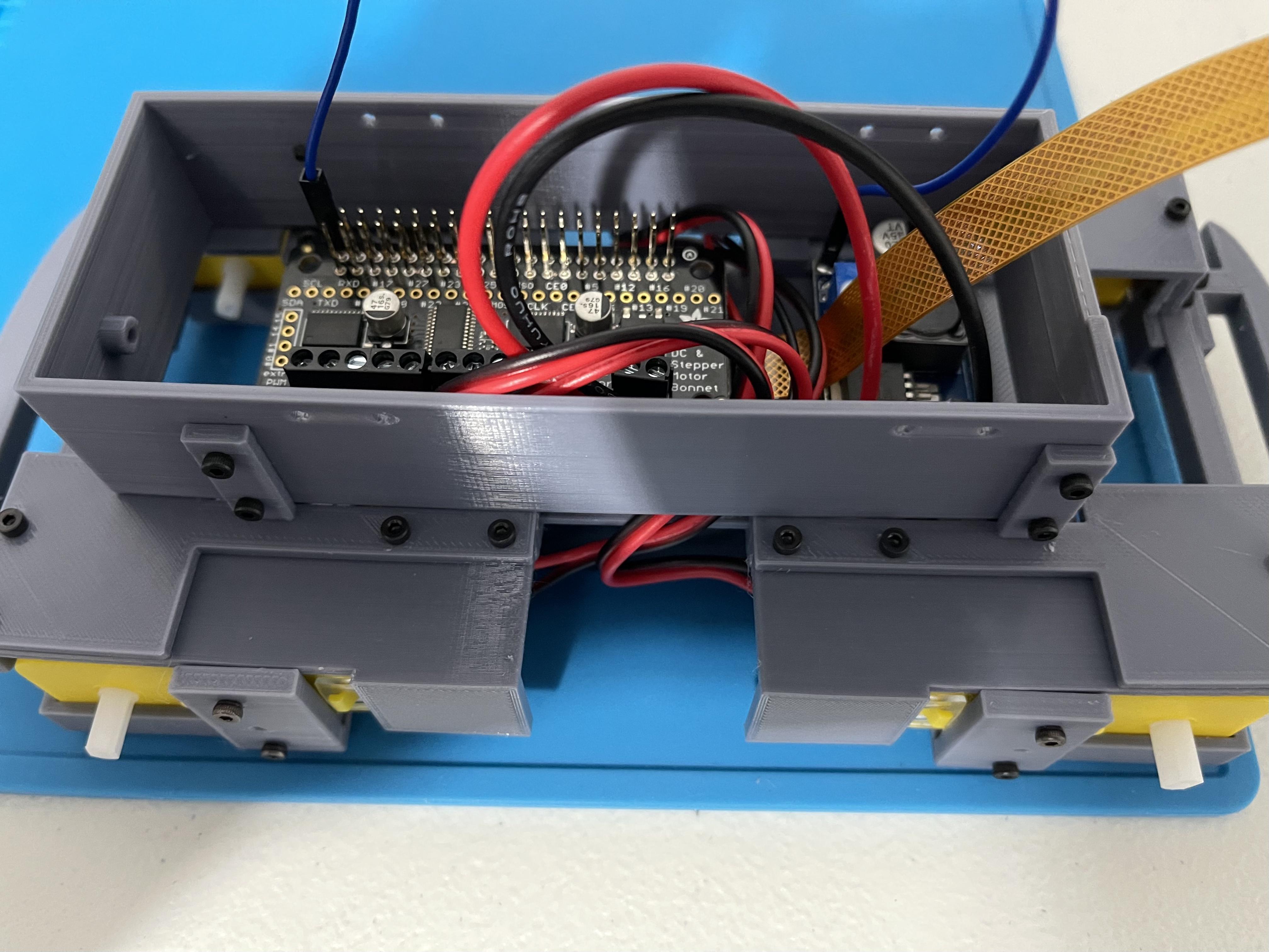
Arrange the wires as needed and mount the chassis (cover) using 8 pcs 6mm hex-head M2 screws.
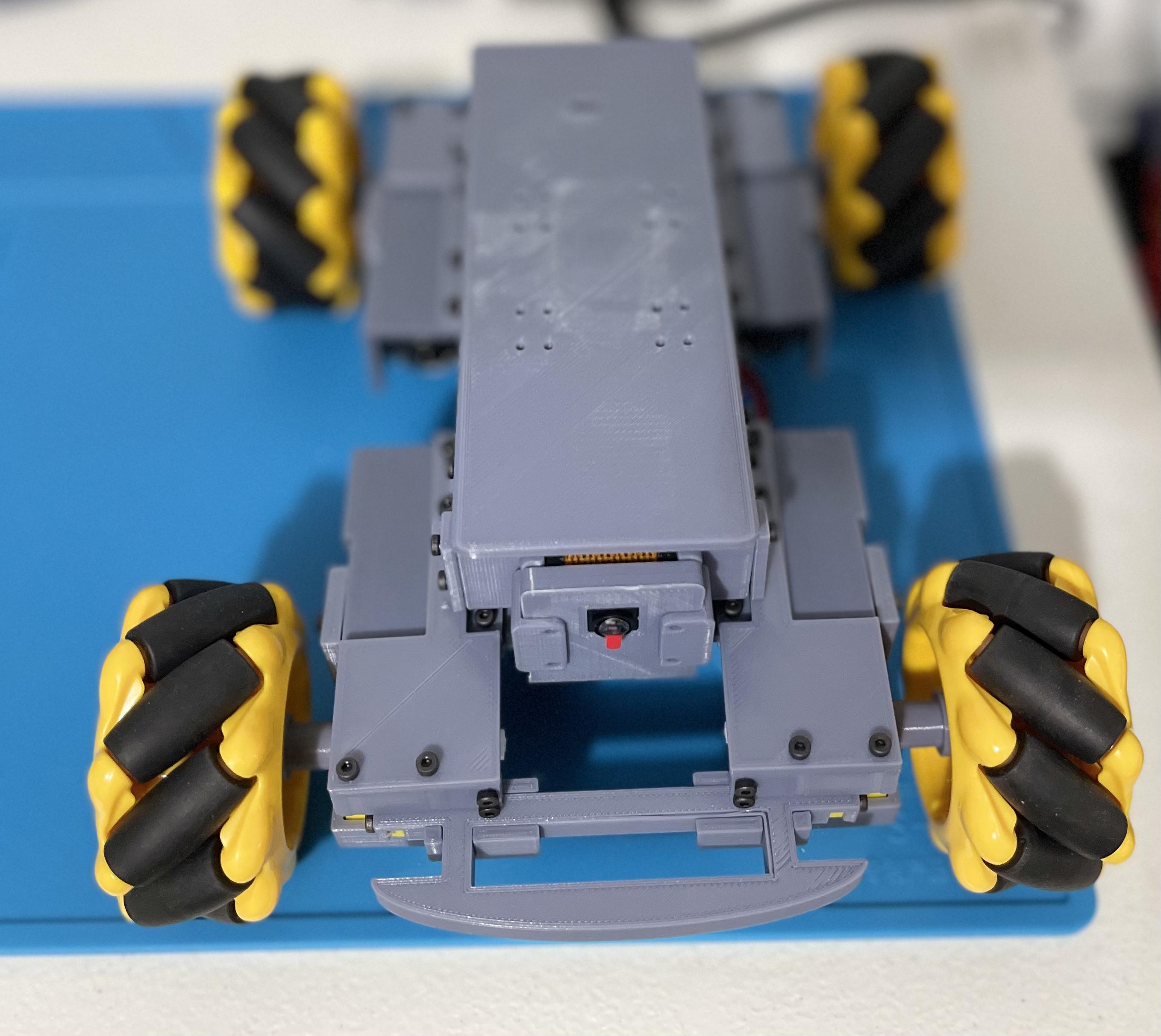
Install the Pi Camera
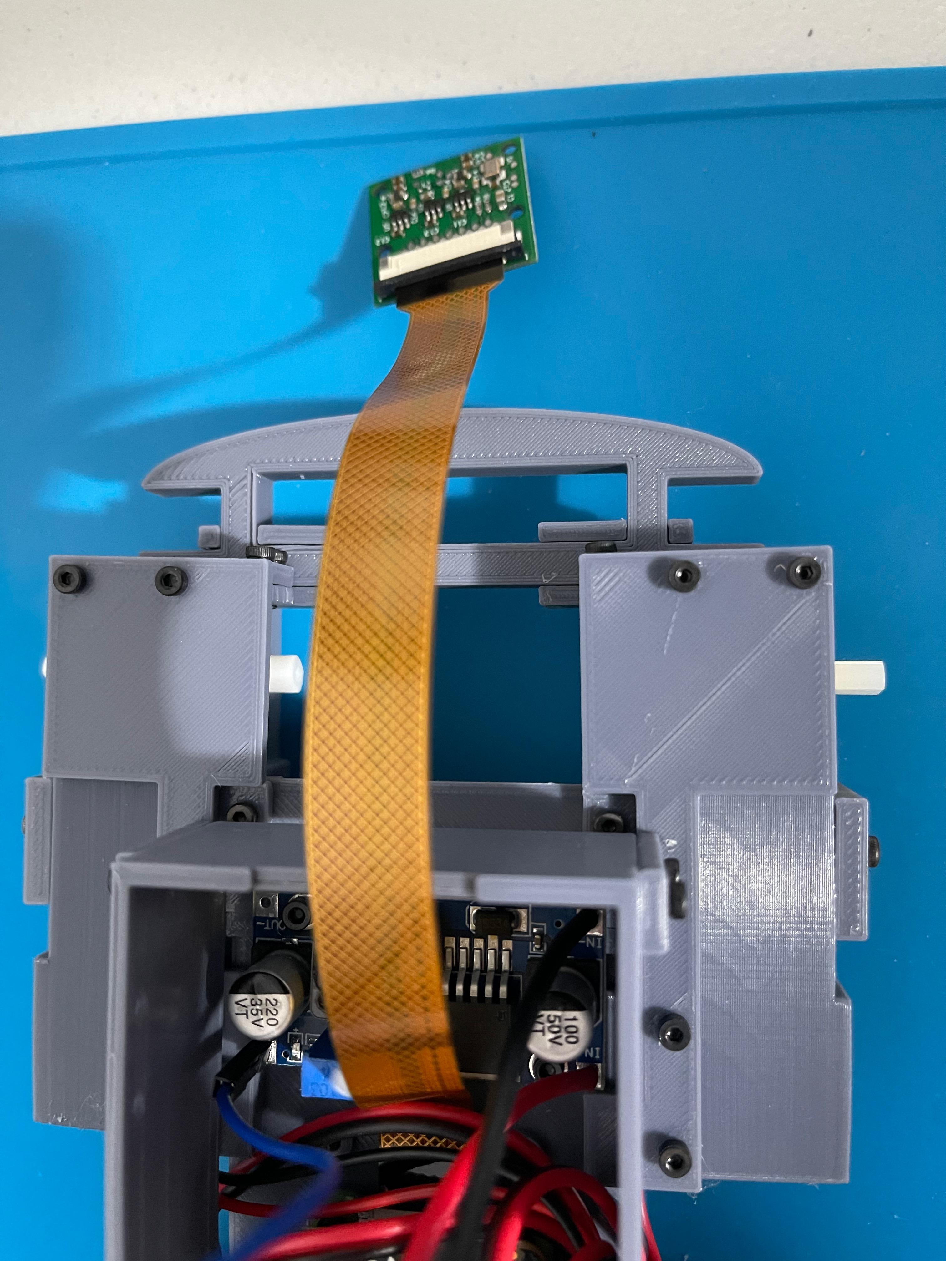
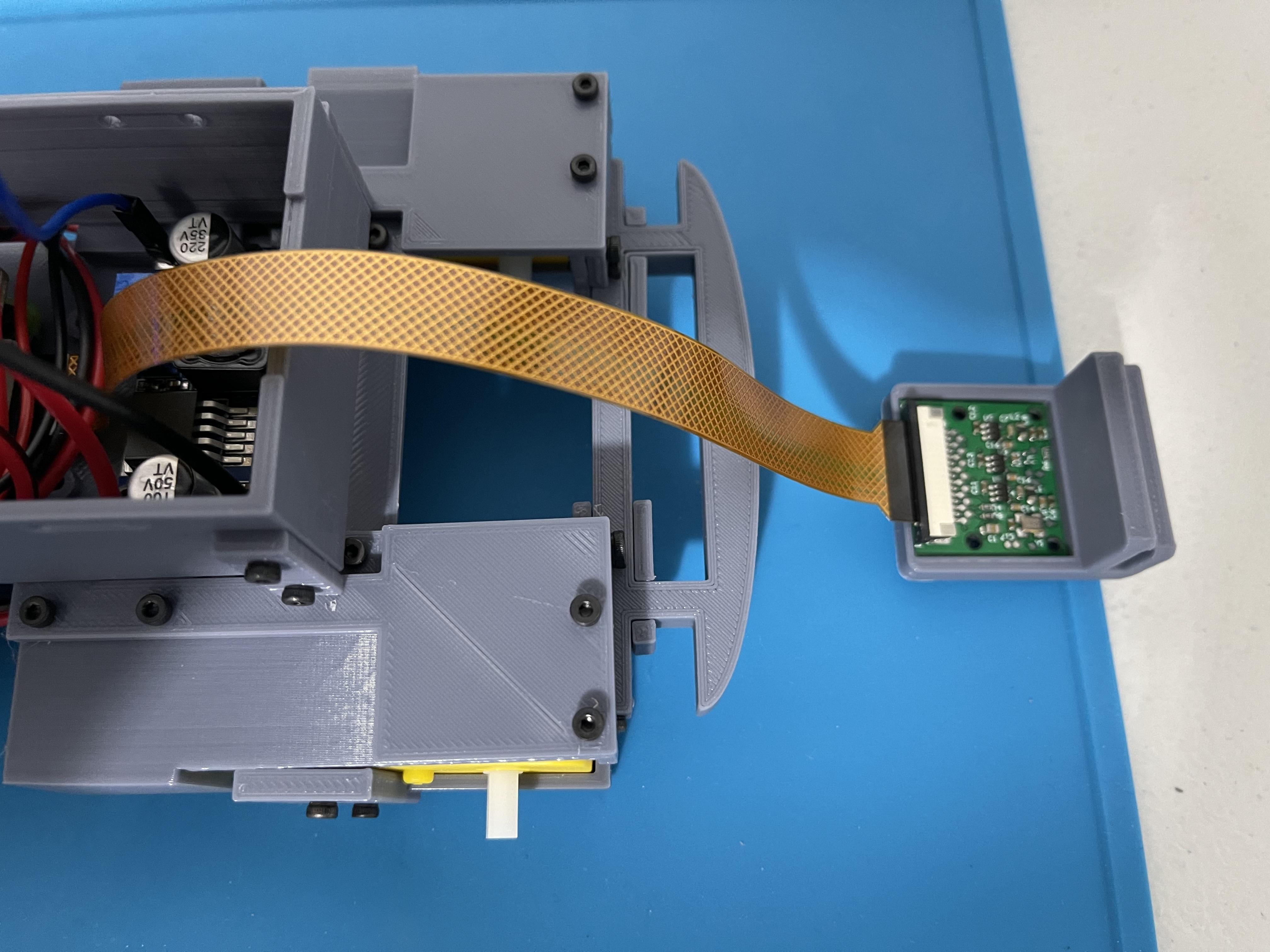
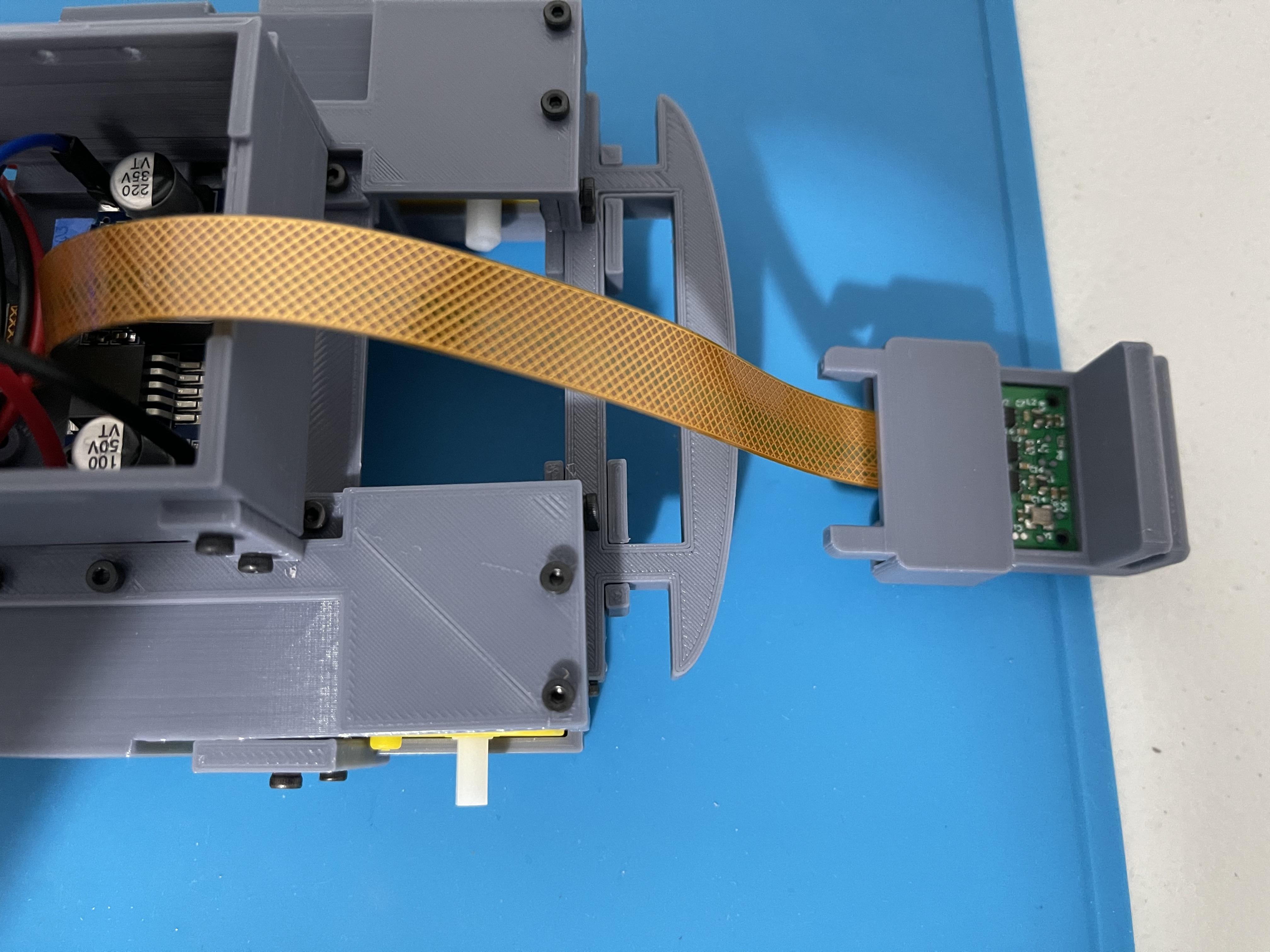
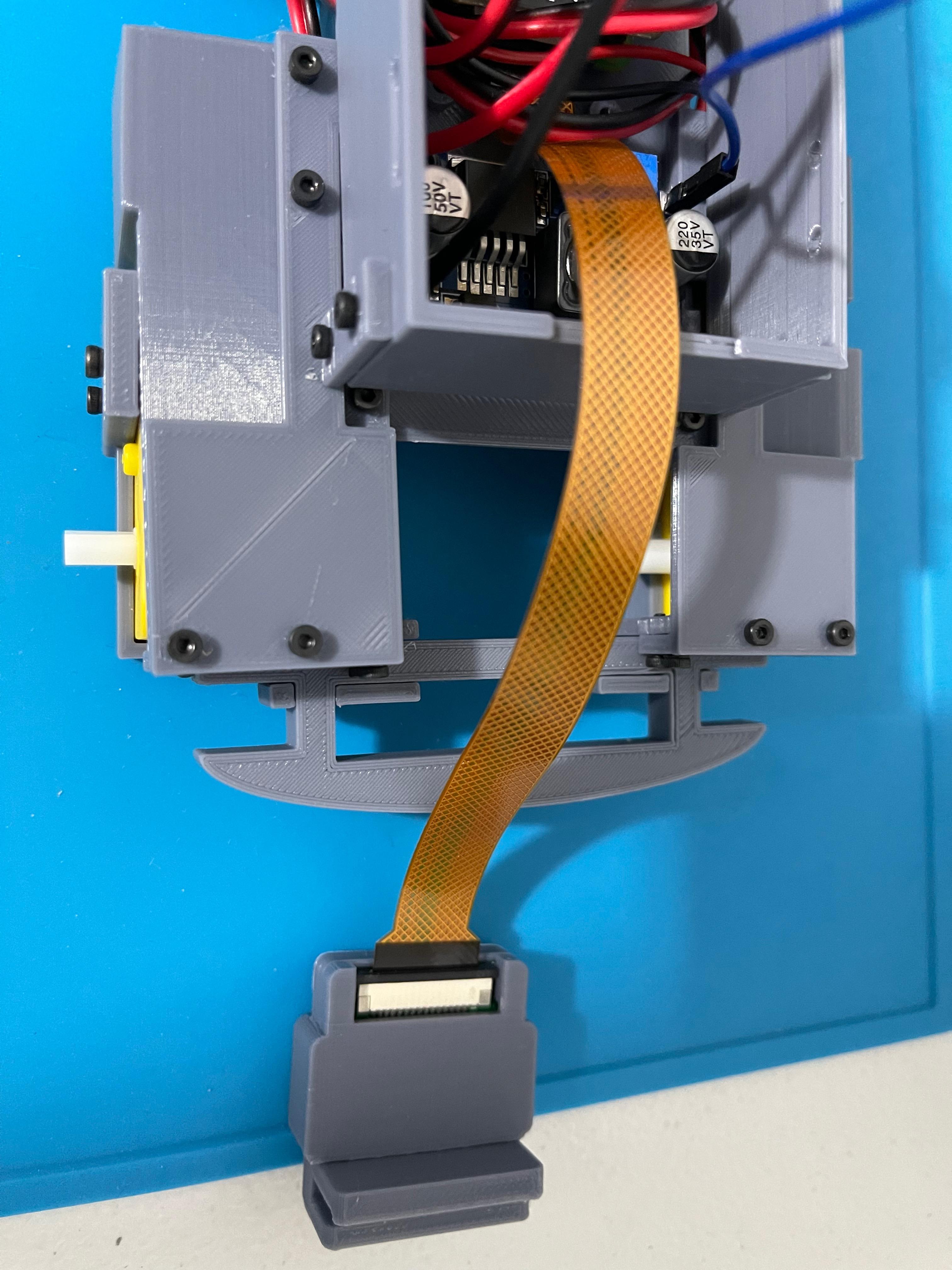
- Connect the other side of the ribbon cable to the Pi Camera. (Contacts are facing down towards the direction of the lens)
- Install the Pi camera in its housing.
- Slide the Pi Camera in its housing to the rover base. Notice that the flex cable of the camera will be softly twisted. This is normal.
Install the Top Cover
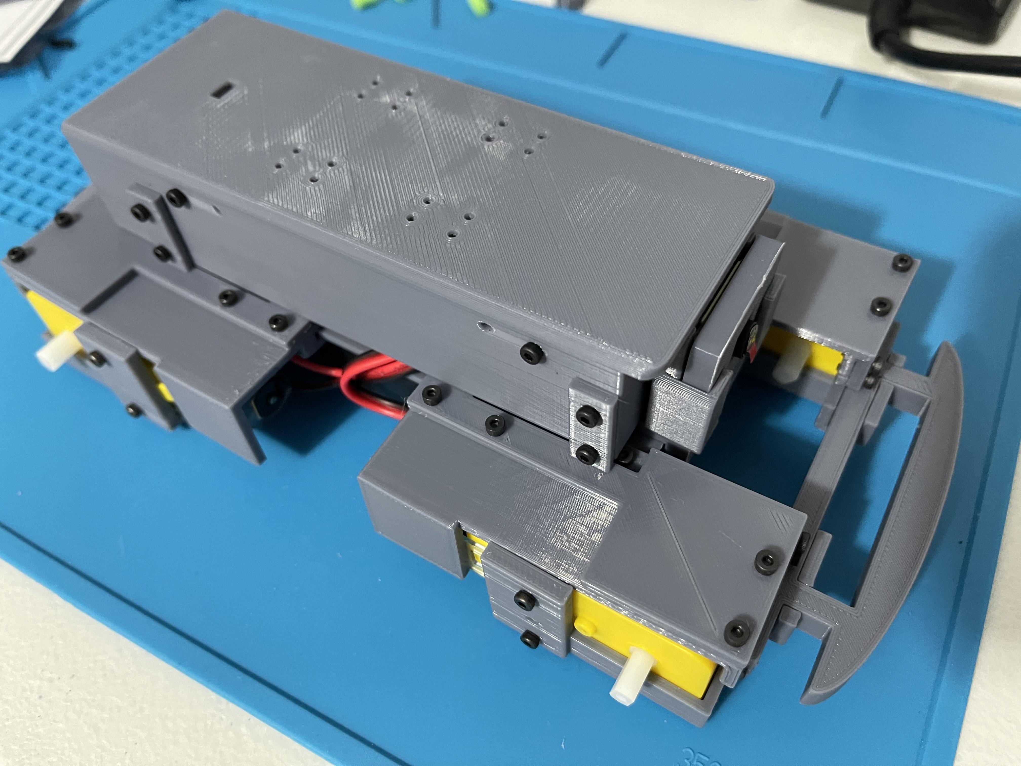
Install the Top Cover (filename: Chassis Top Plus shown on the image) using 6mm hex-head M2 screws to secure it in place.
Installing the Mecanum Wheels
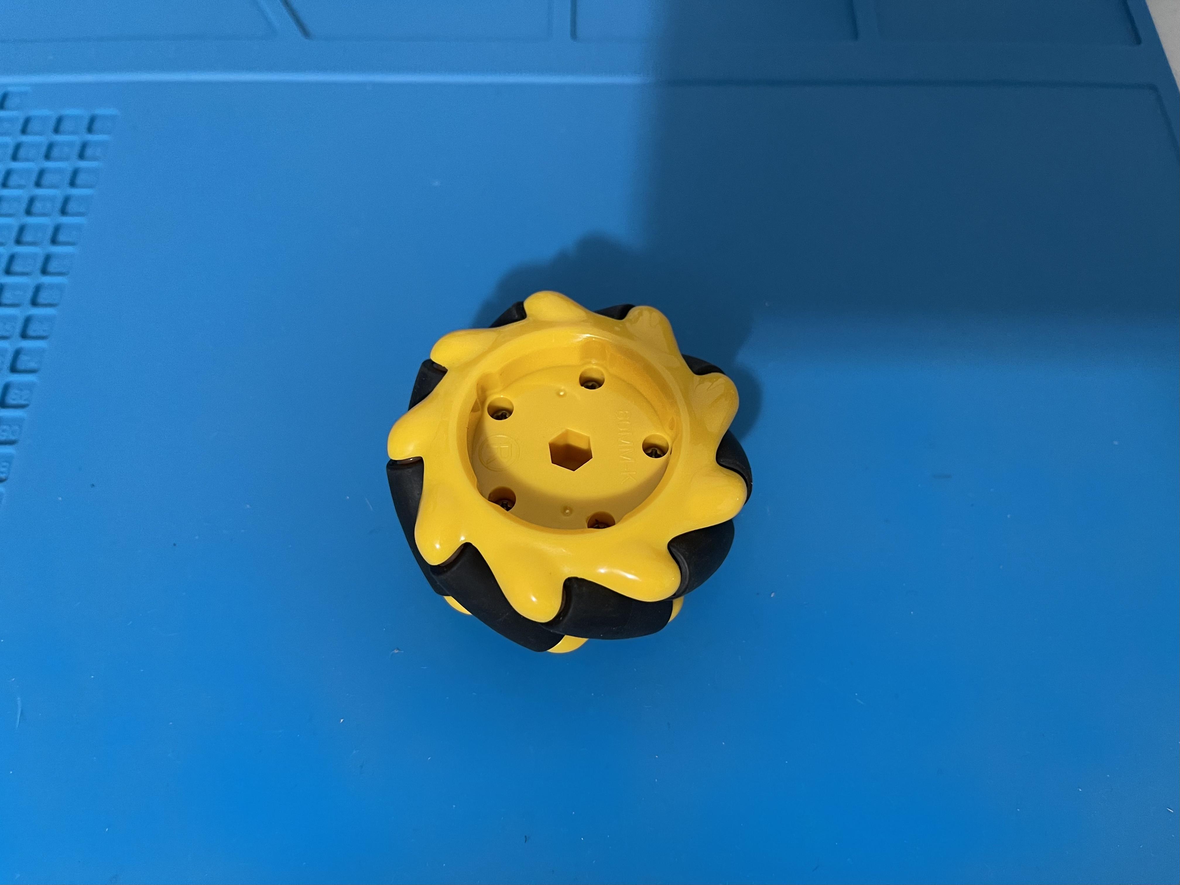
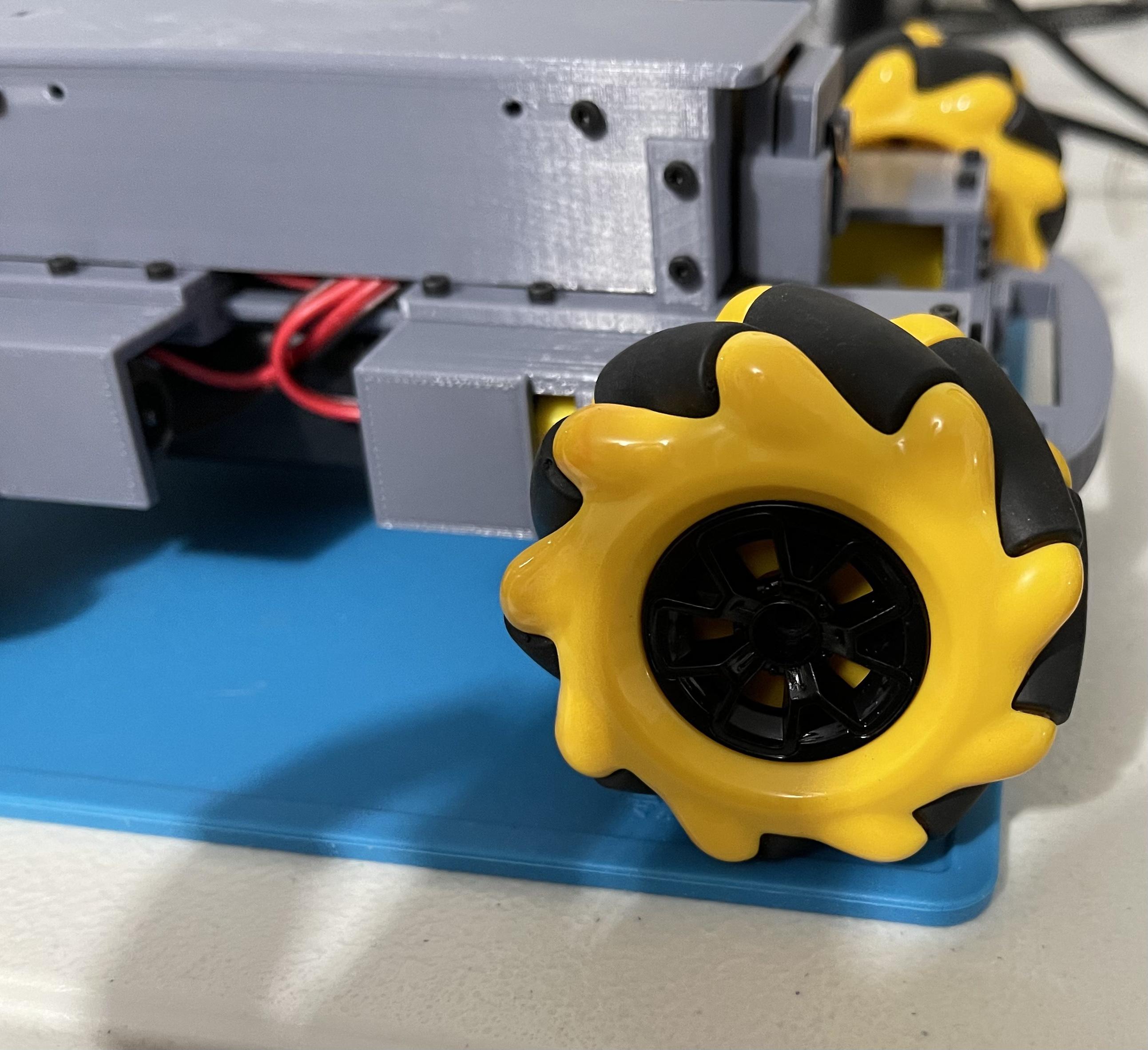
Note: There are different kinds of Mecanum Wheels out there. Each may have a different diameter and a slightly different appearance. What is used for this project is the 60mm black and yellow Mecanum wheel with no adaptor (see image). Some black and yellow Mecanum wheels may come with an adaptor, but so far, those have not been tested (will post an update if they can be supported. For now, to ensure proper fitting, only use Mecanum Wheels that look closely identical to the shown image or as linked in this project.
- Use an 8mm cross-head M2.3 screw to attach 1st part (filename: Mecanum Wheel Adaptor 1) of the Mecanum Wheel adaptor to the motors.
- Use 2 pcs 6mm hex-head M2 screws to attach the 2nd part (filename: Mecanum Wheel Adaptor 2 (2mm)) of the Mecanum Wheel adaptor to the 1st part.
- Install the Mecanum Wheels and secure them in place using 10mm hex-head M2 screws.
Play With the Newly Built Rover (Example Code)

ENJOY!!!
Note: This project is still evolving so stay tuned for new updates and add-ons. All 3d printed parts are designed by yours truly. If you like this project, not mandatory, but you can always show your love by clicking here. Thank you for your appreciation and for giving this project a chance!
Test your Rover:
- Turn on the rover
- Wait for the Pi to fully boot up and log in to it via SSH.
- Once logged in, turn on your game controller, run Python 3 and copy/paste the code from DC-Rover Github Page
- Use the left analog stick on your game controller to move the rover around, the left and right d-pad buttons will make it move left or right without turning, Cross/A button will take photo snapshot with the Pi camera and Circle/B button will take a 5 second video. (Feel free to modify/play with the code).