DC Motor Starter Using Arduino Uno
by Anto B in Circuits > Arduino
7420 Views, 0 Favorites, 0 Comments
DC Motor Starter Using Arduino Uno
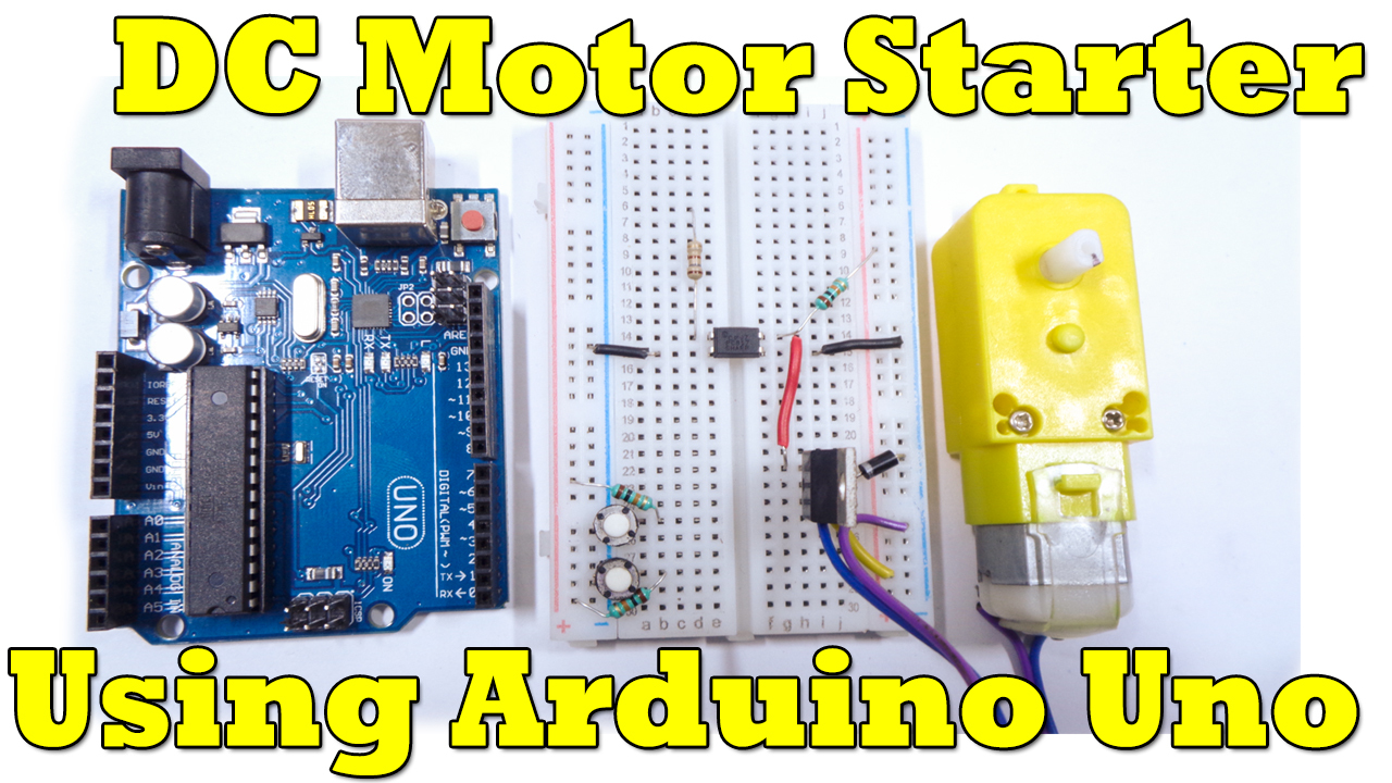
A motor soft starter is a device used with DC motors to temporarily reduce the load and torque in the power train and electric current surge of the motor during start-up. This reduces the mechanical stress on the motor and shaft, as well as the electro-dynamic stresses on the attached power cables and electrical distribution network, extending the lifespan of the system.
In this Tutorial we are going to make a simple DC Motor Starter Using Arduino Uno.
Supplies
Materials required:-
Arduino uno
PCF817
p-channel IRF9530 MOSFET
1N4007 rectifier diode ,
12V DC motor
Push button - 2 nos
10K resistor - 3 nos
100E resistor - 1 nos
+12v power supply - 1 nos
Gather the Necessary Components to Do Our Project
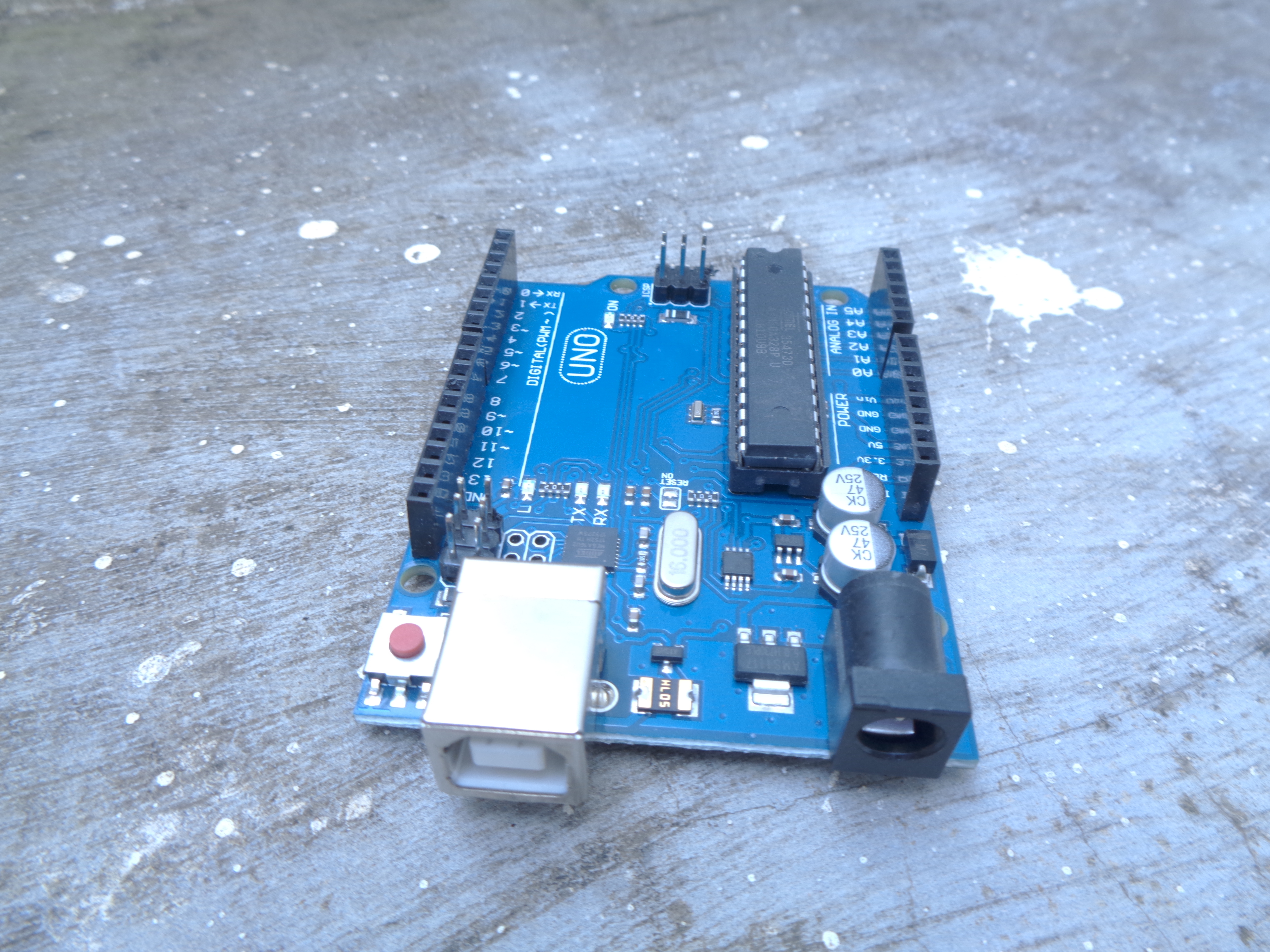
Arduino Uno is used in our project. Because we are going to control the speed of the motor using the PWM pheripheral. arduino UNO has 6 PWM pheripheral. so we are using the pin number 9 (D9) of the arduino board in this project.
PCF817 OPTO COUPLER is used on the circuit because to safe guard the arduino board from the reverse current produced by the motors coil. so we are going to give external power to the motor. you can check this on the circuit diagram.
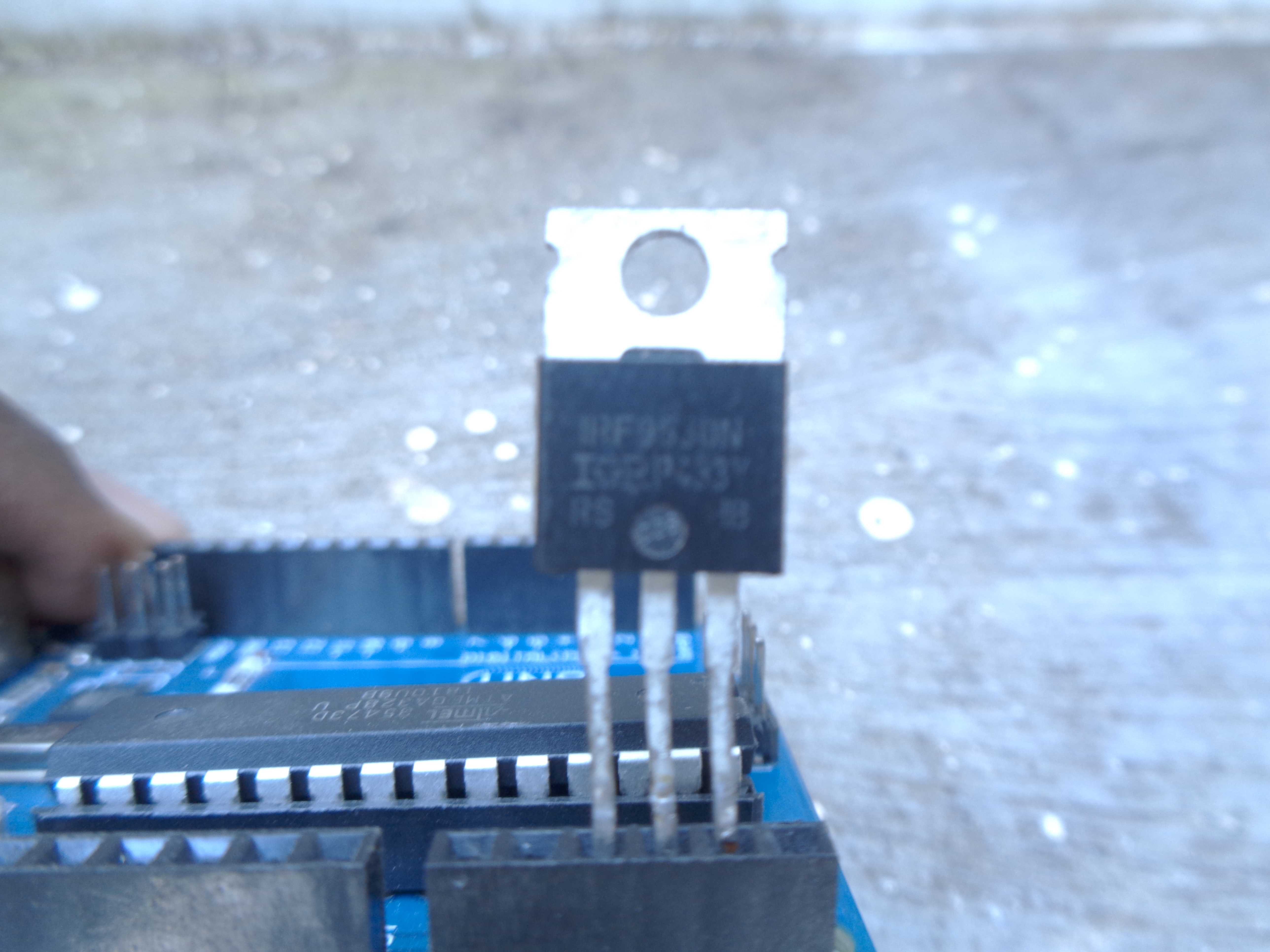
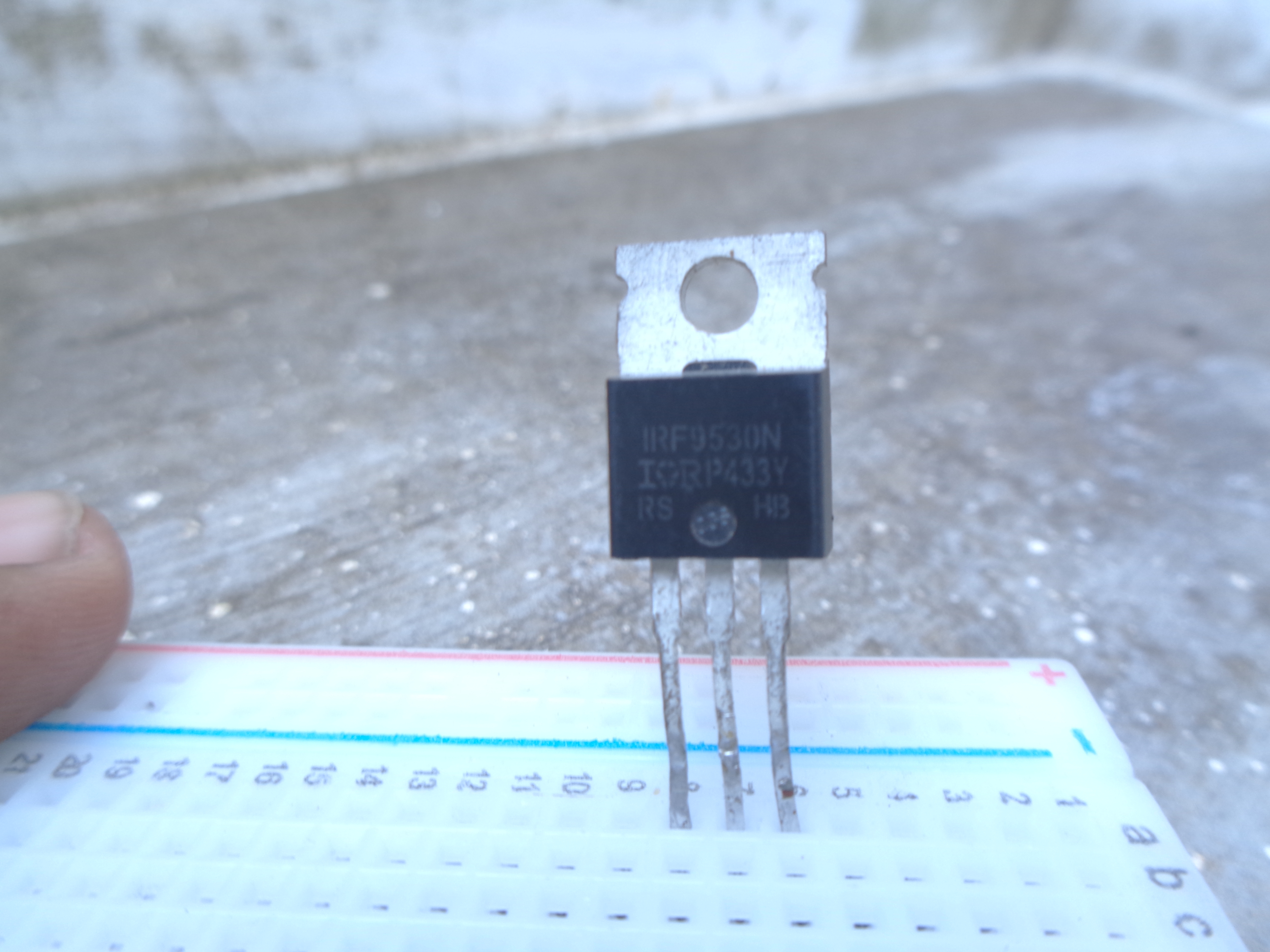
IRF9530 P-channel MOSFET used to control the motor. because it can resist heat even if we provide high current.
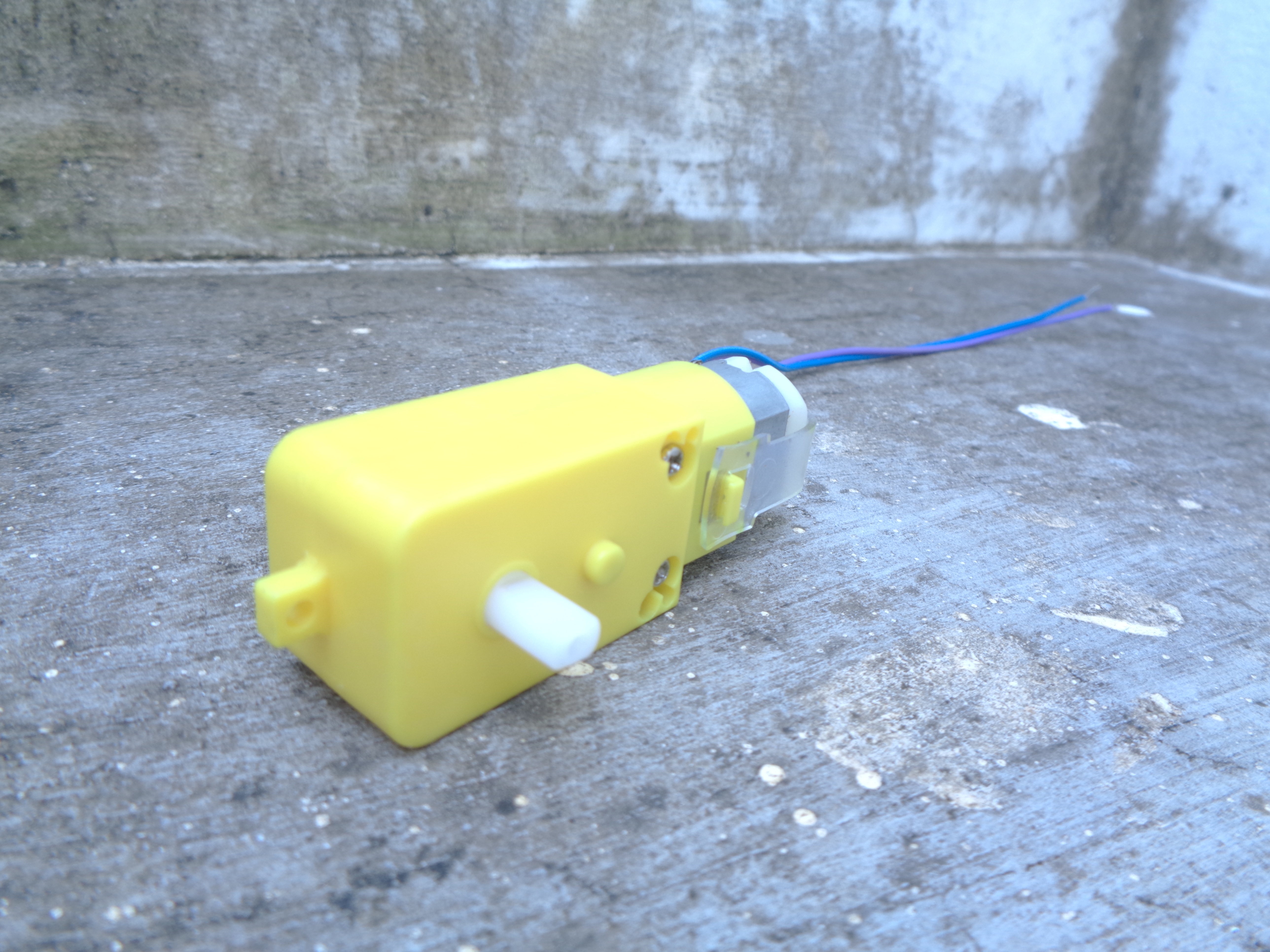
I used the BO Motor to test. you can use any kind of DC motor based on your requirement.
LIVE DEMO IS ON MY YOU TUBE CHANNEL.. LINK GIVEN AT THE END...
Connect the Optocoupler at the Middle of the Breadboard
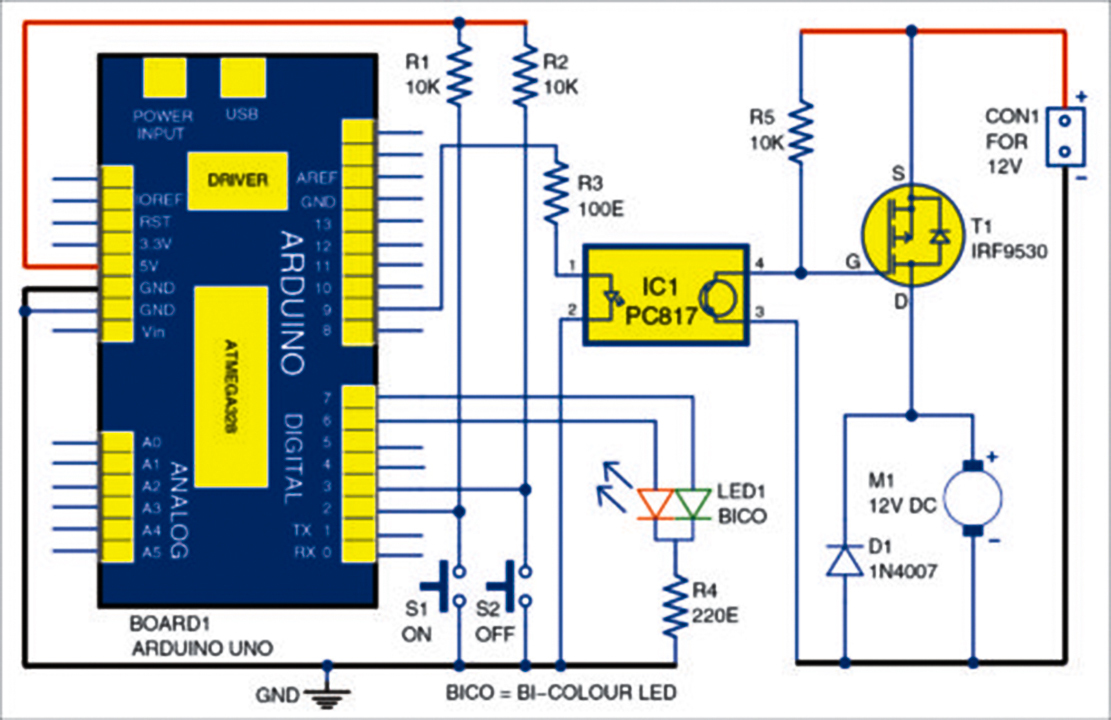
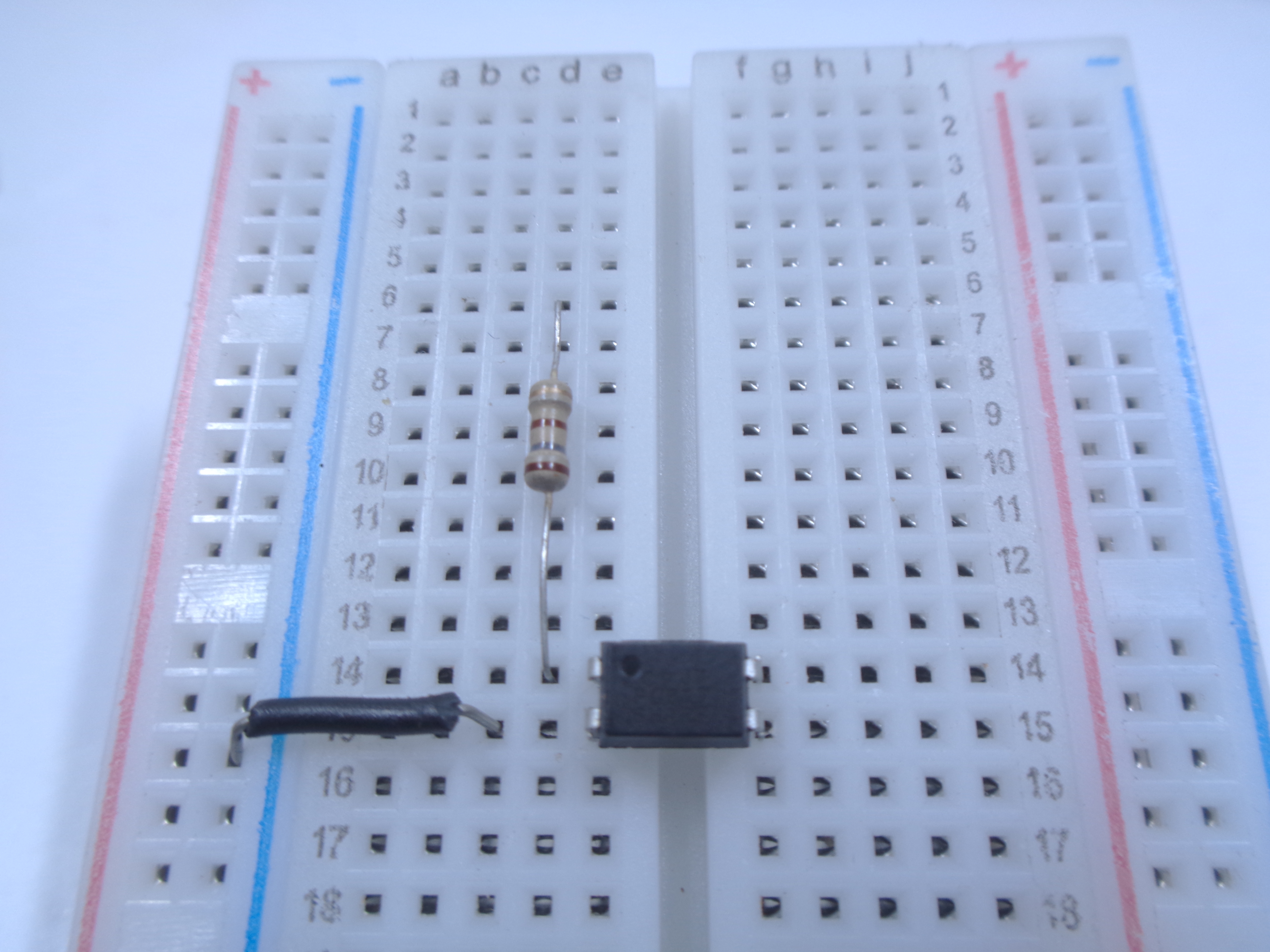
Remember the circuit diagram and connect as per the circuit diagram
Connect the 100E resistor to the 1st pin of the optocoupler.
connect the 2nd pin of the optocoupler to the negative series of the breadboard as per the picture.
Place 2 Push Buttons and 10k Resistors Then Place Mosfet
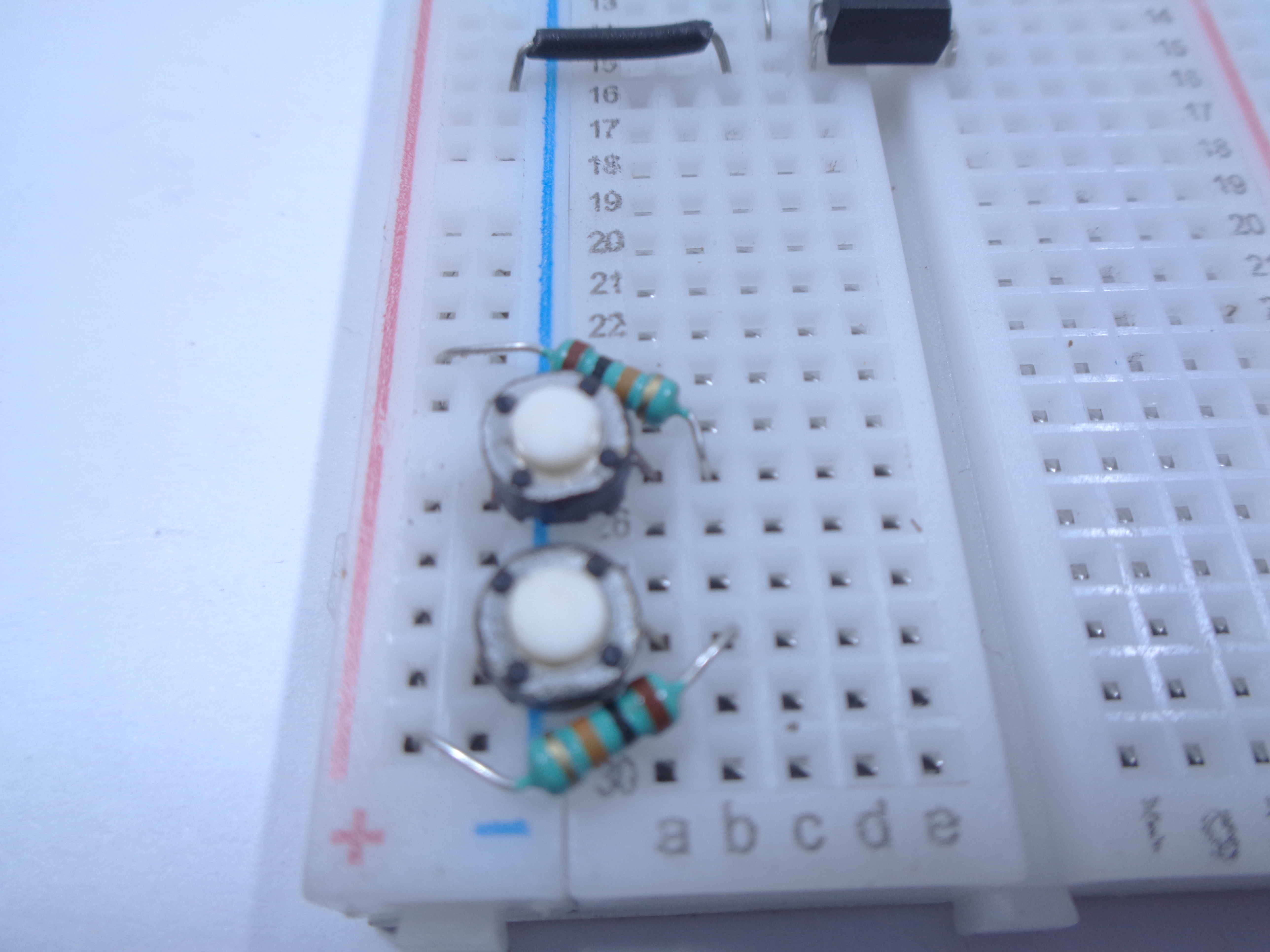
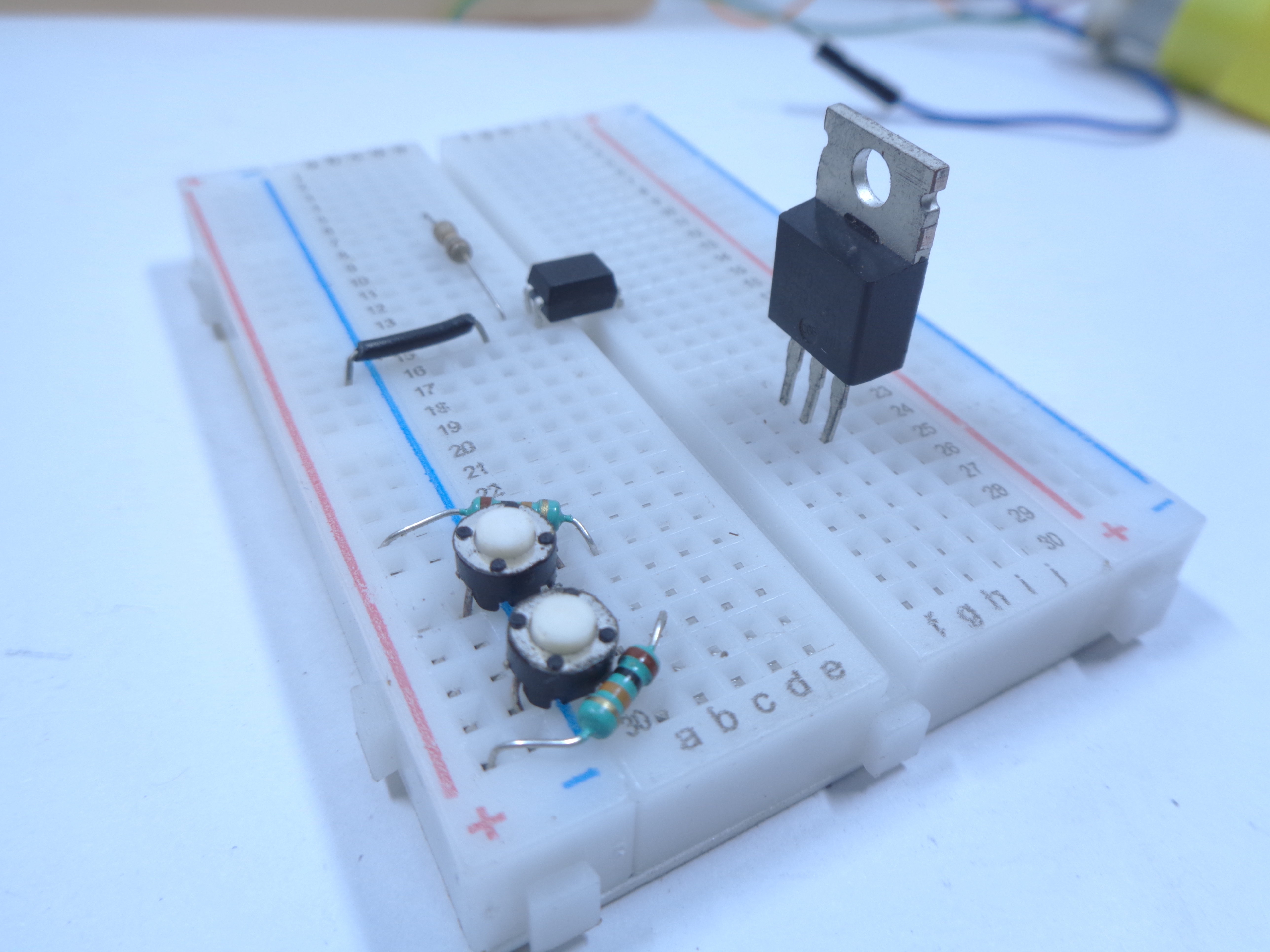
Place 2 push buttons to Switch ON and Switch OFF the motor. we are going to fed active low to the microcontroller. so that we have to connect 2 number of 10k resistors parallel to the bush button and arduino. so connect the other end of the resistor to the positive row of the breadboard as per the picture.
Place the IRF9530 Mosfet on the bread board.
Connect 10K Resistor to the 4th Pin of the OPTO COUPLER to the +12v
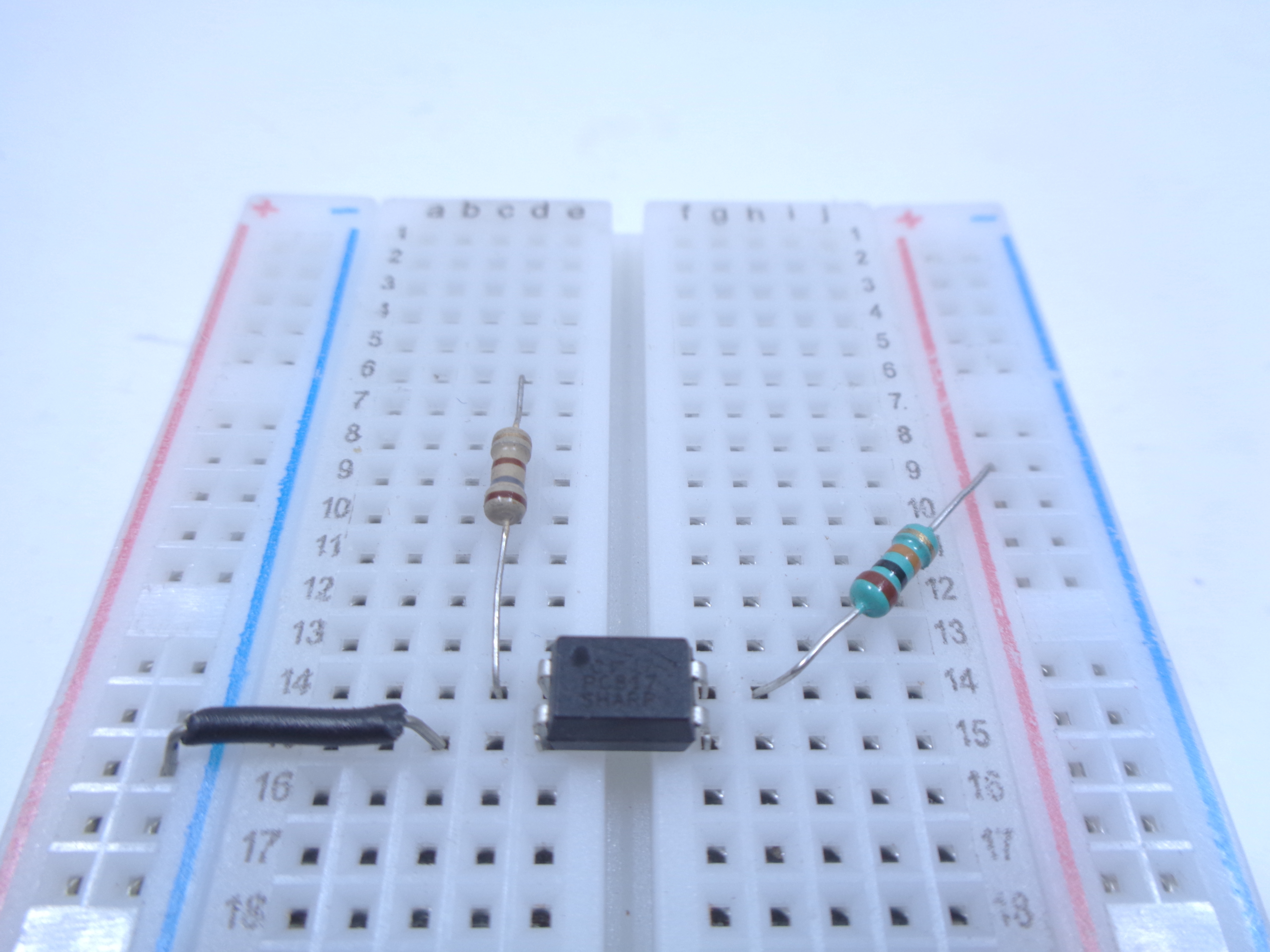
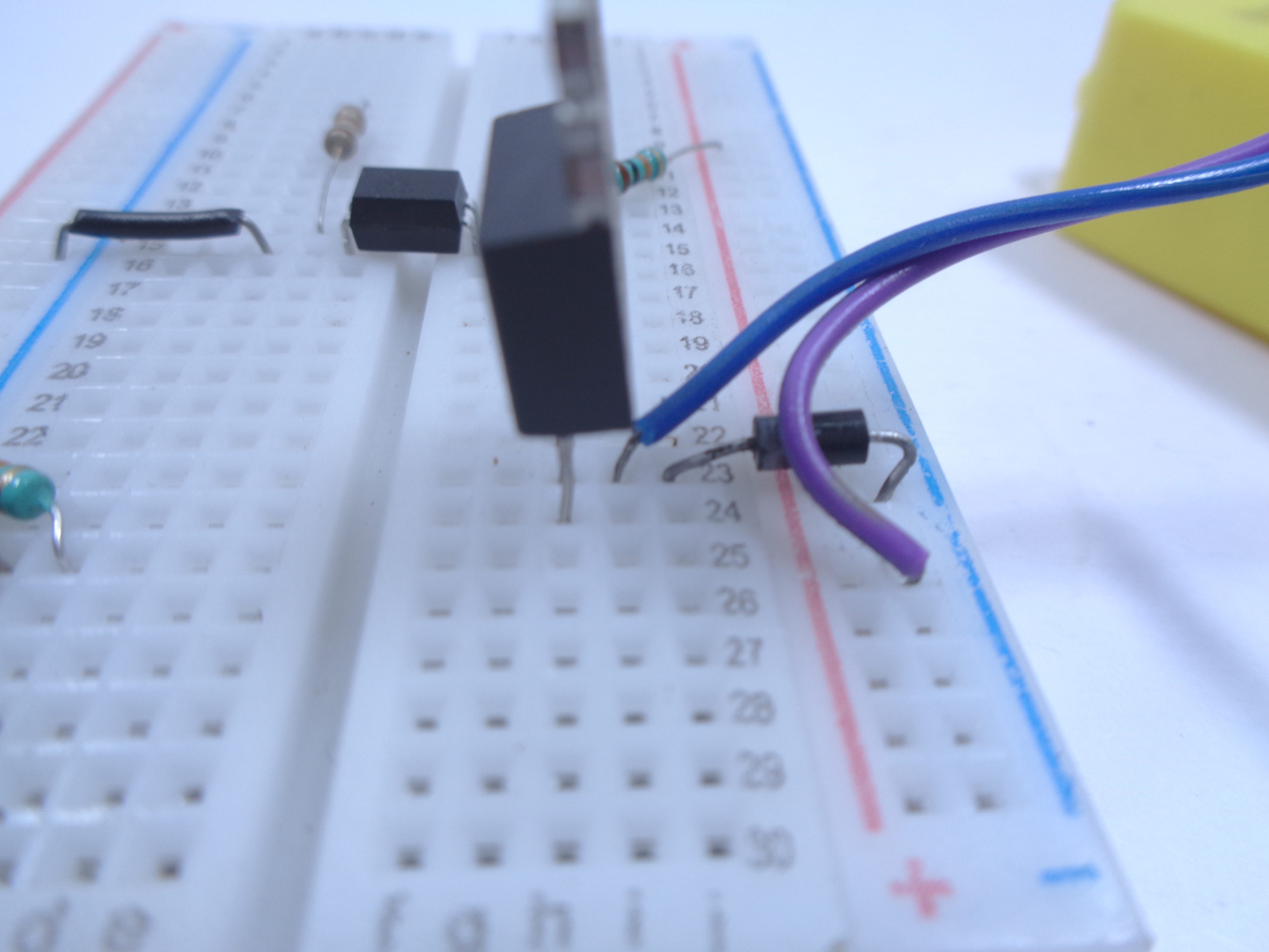
connect the 4th pin of the optocoupler to 10k resistor and the other terminal of the resistor to the other positive row in the bread board.
Connect the feed back diode to the Drain terminal of the mosfet.
connect the dc motor parallel to the Drain terminal of the mosfet.
connect the opposite end of the diode and motor to the negative row in the bread board.
Connect the Source to Fed +12v for the Motor
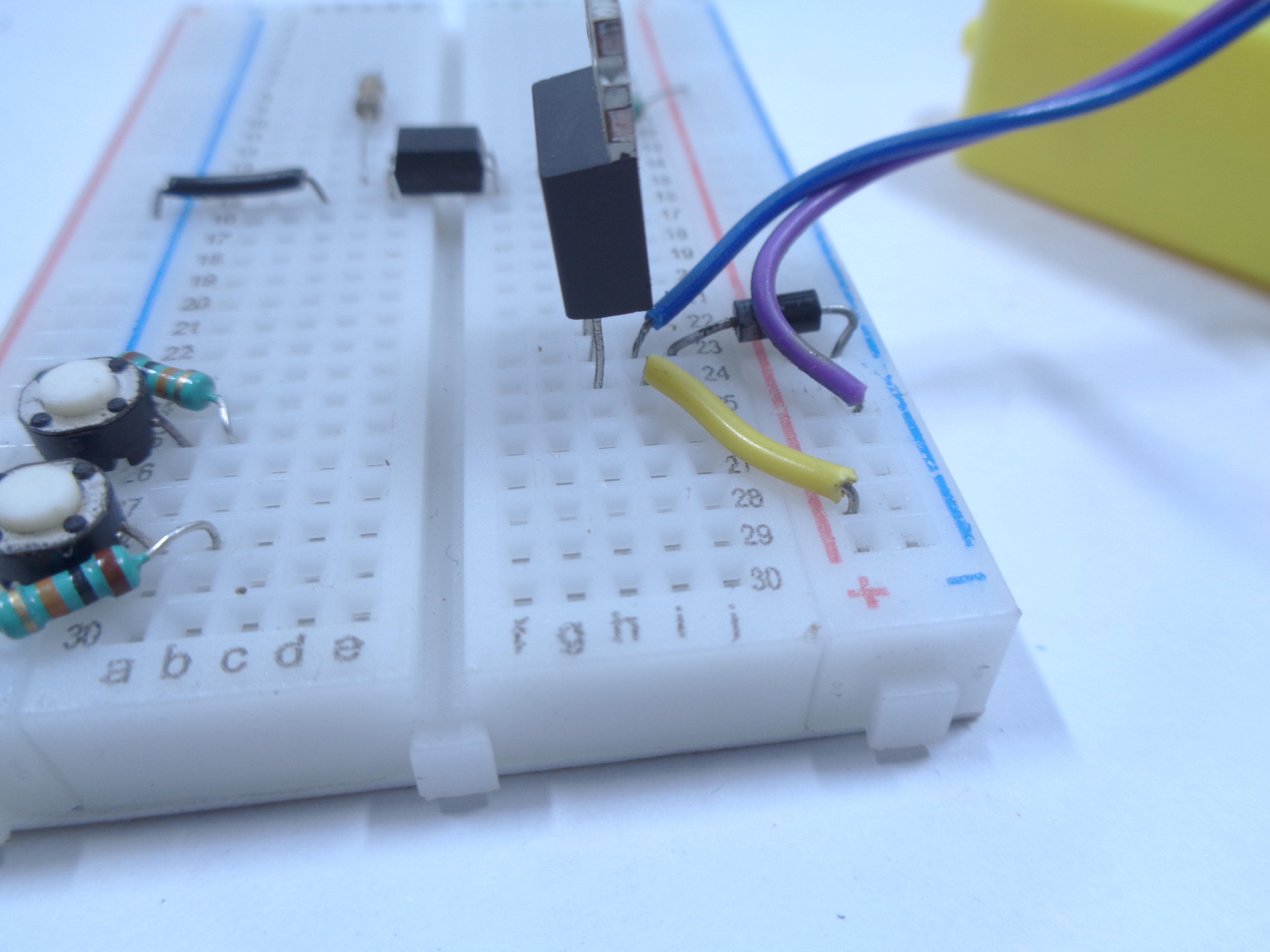
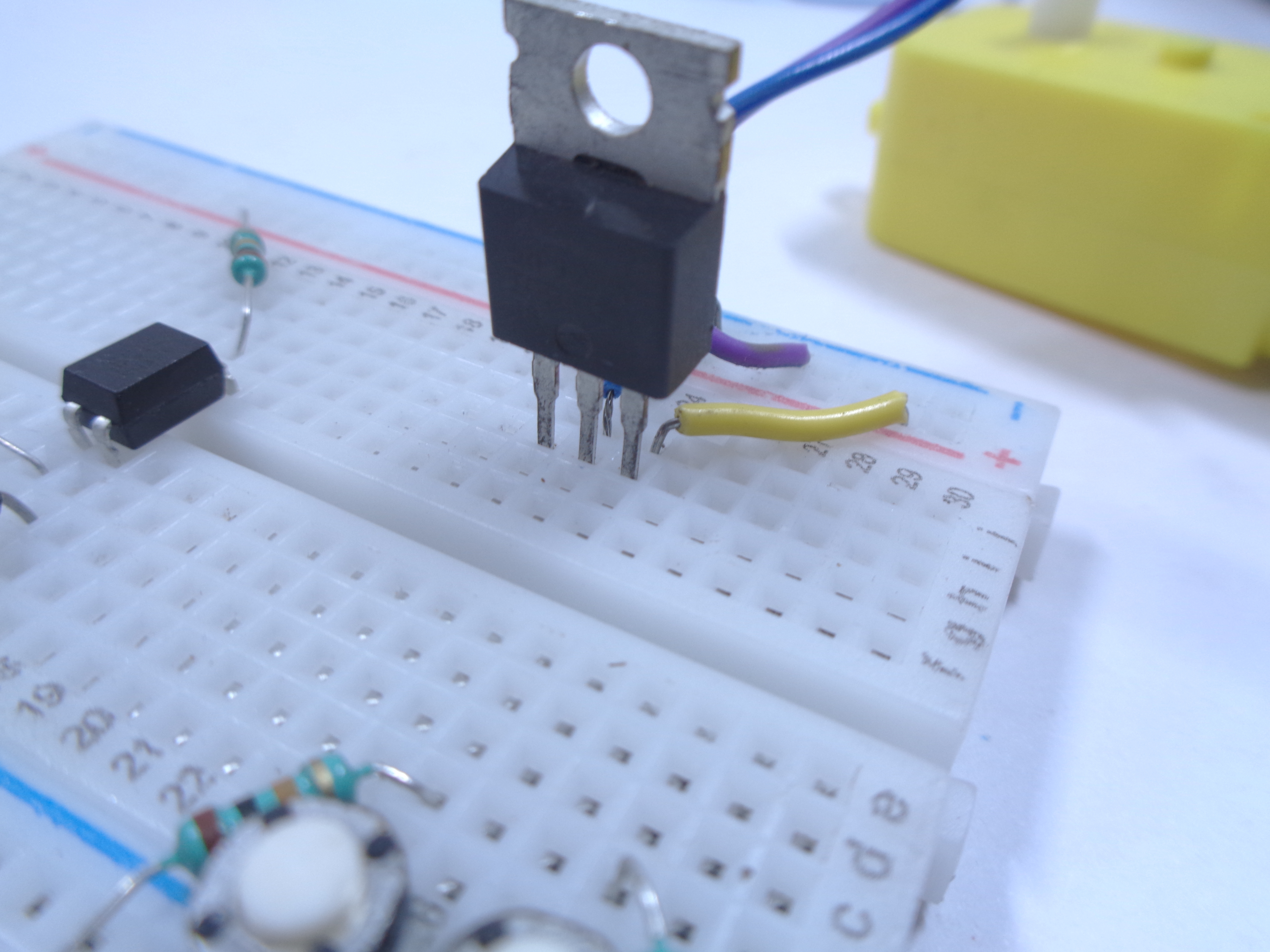
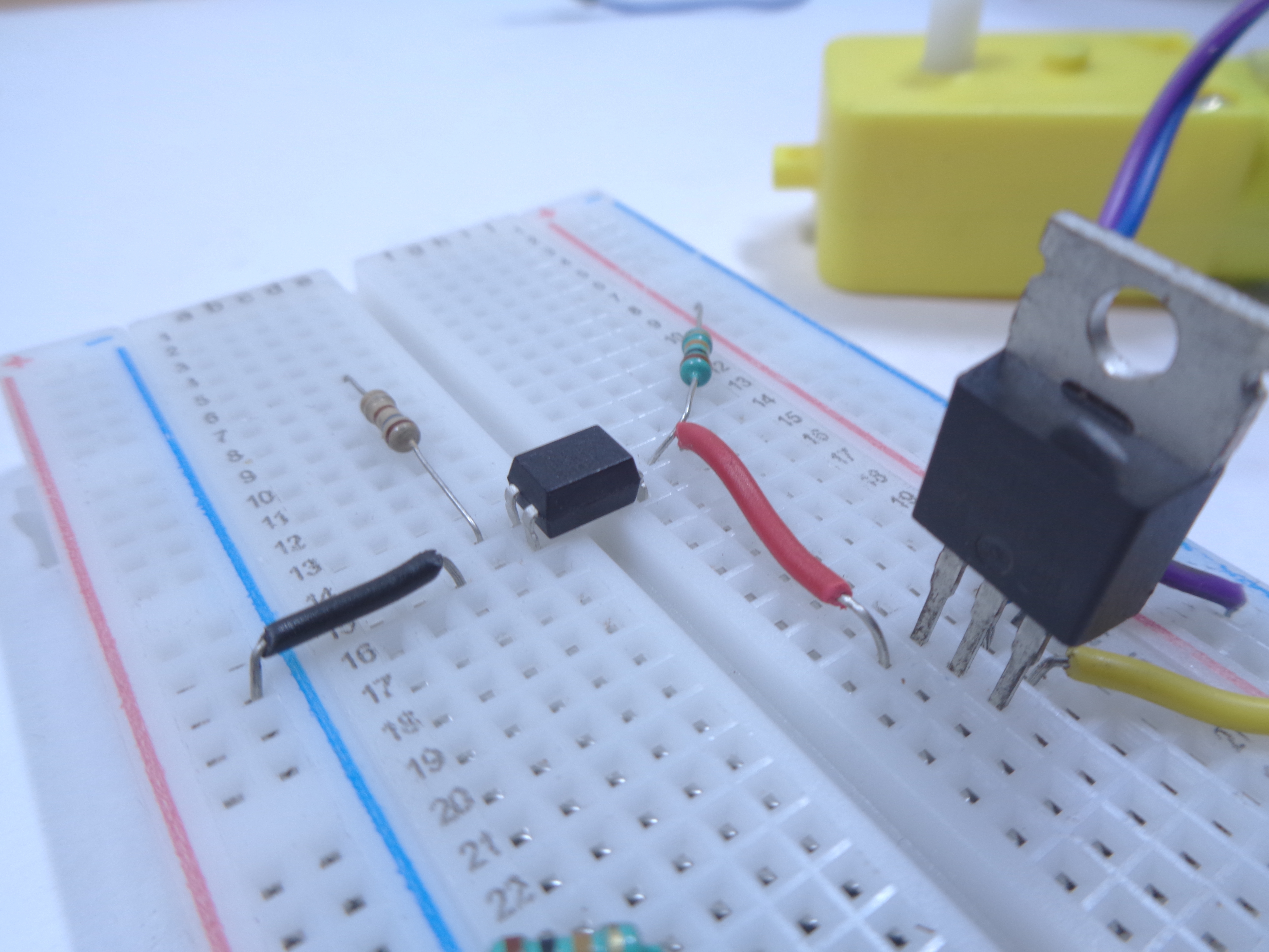
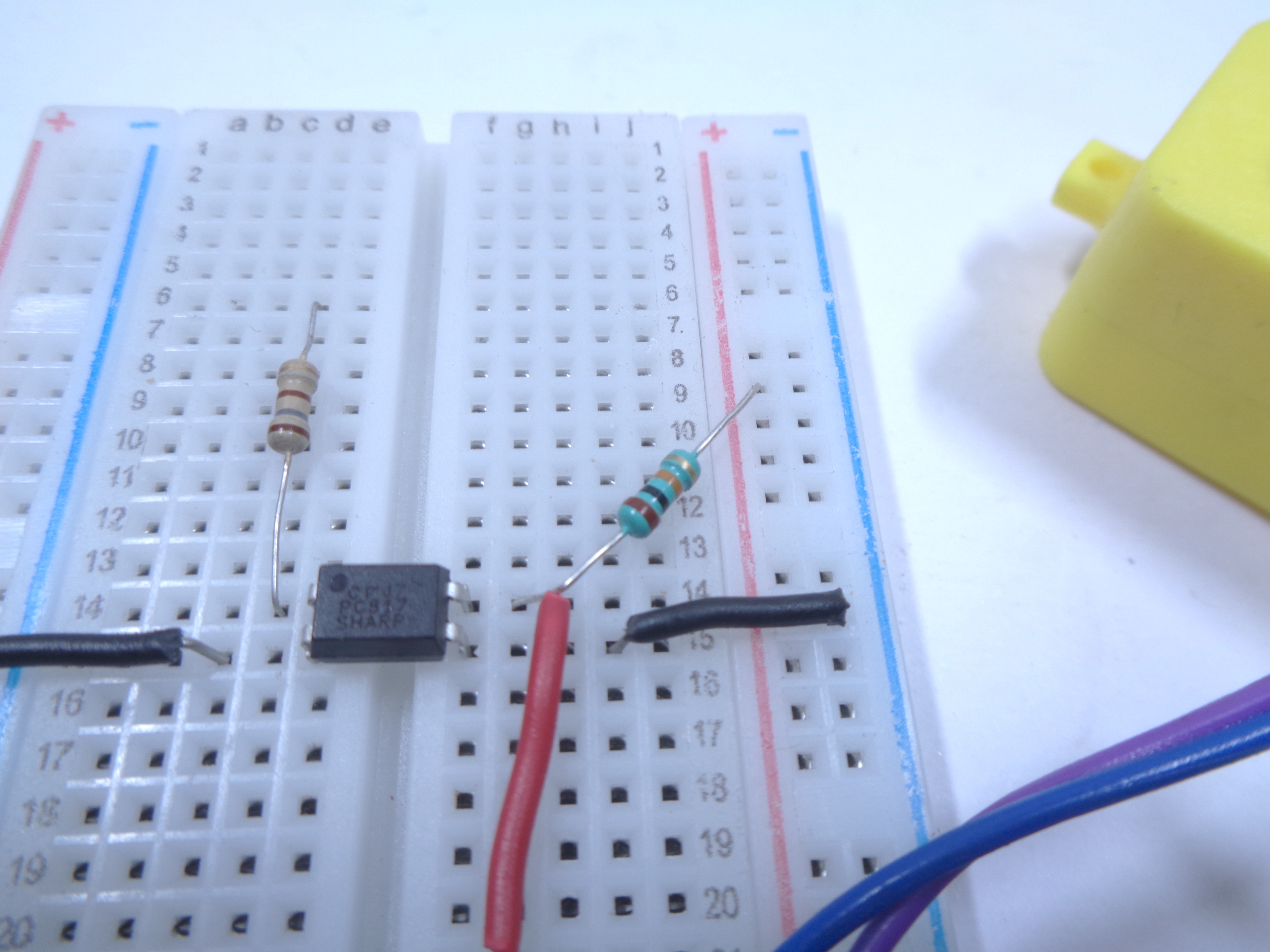

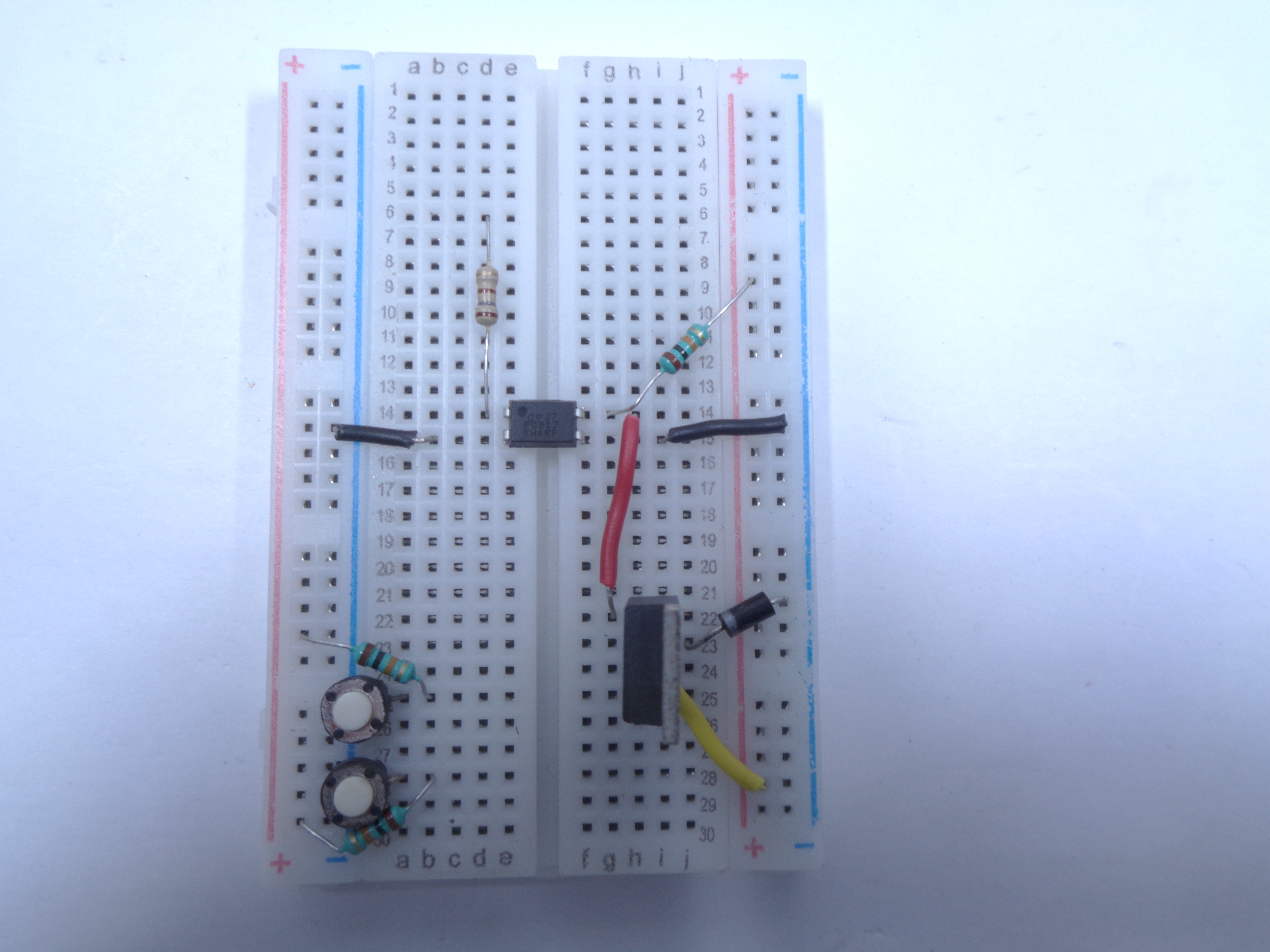
connect the SOURCE terminal to the positive row to fed +12v for the motor
connect the 3rd pin of the arduino to the gate of the mosfet. i have connected with red wire.
Give +5v at the Leftside From the Arduino and +12v at the Right Side Using External Power Supply
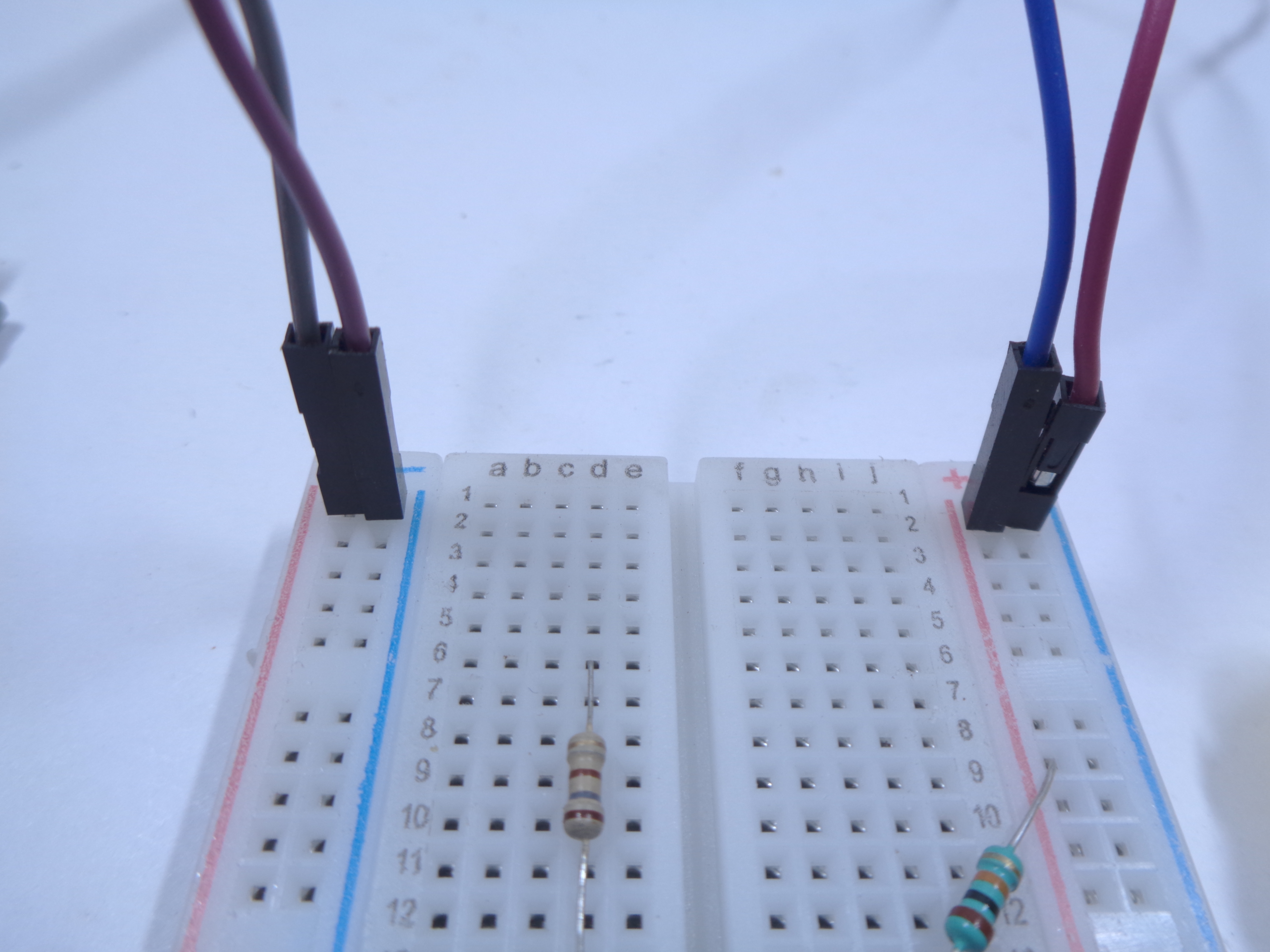
Time to give two different power supply. be careful.
Don't short circuit.
Connect the Other Jumper Wires for Input
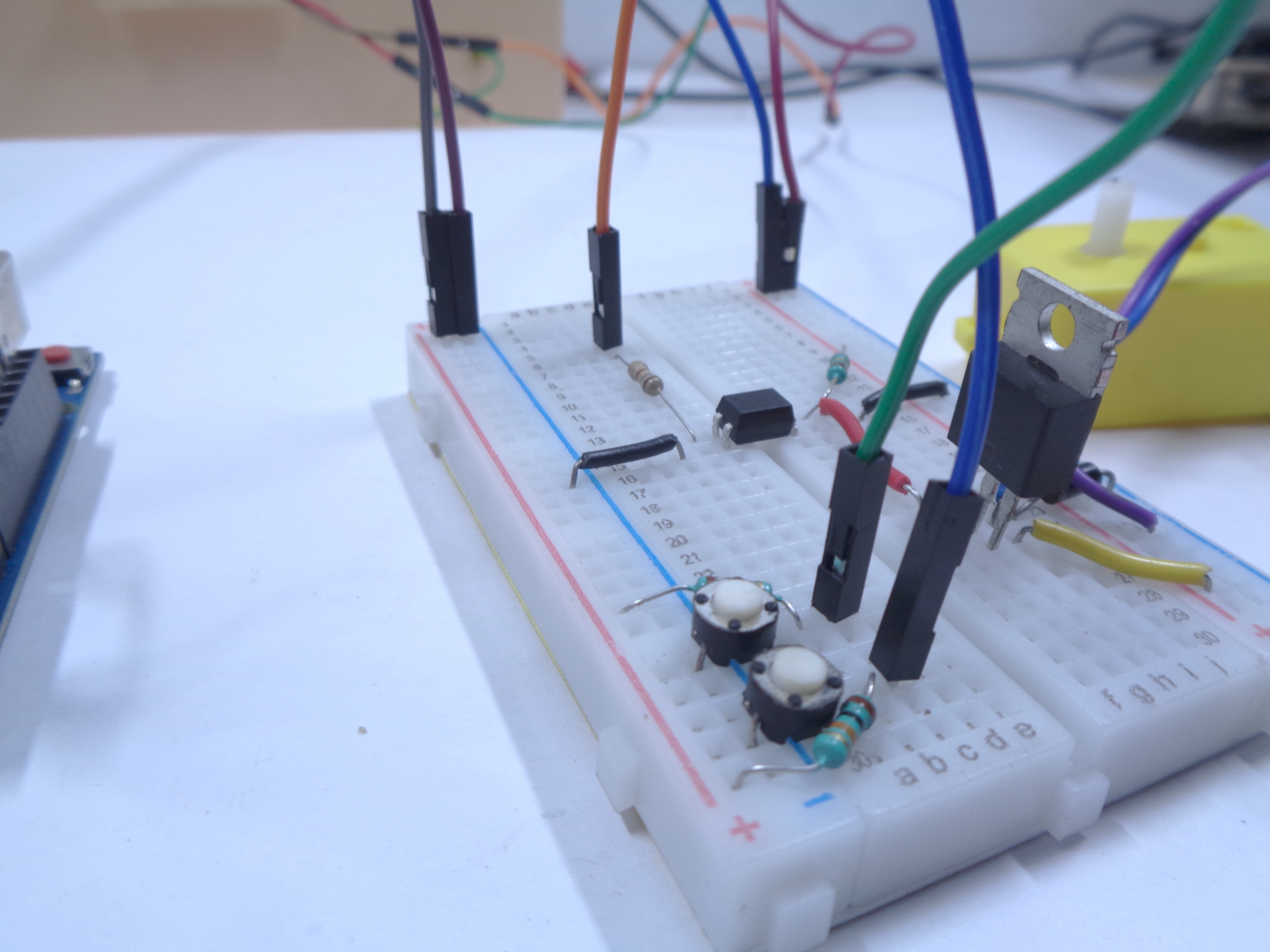
connect D9 from arduino to the 100E resistor
connect D2 from arduino board to the one terminal of the switch
connect D3 from arduino board to the another one terminal of the switch
Download the Code in the Attachment
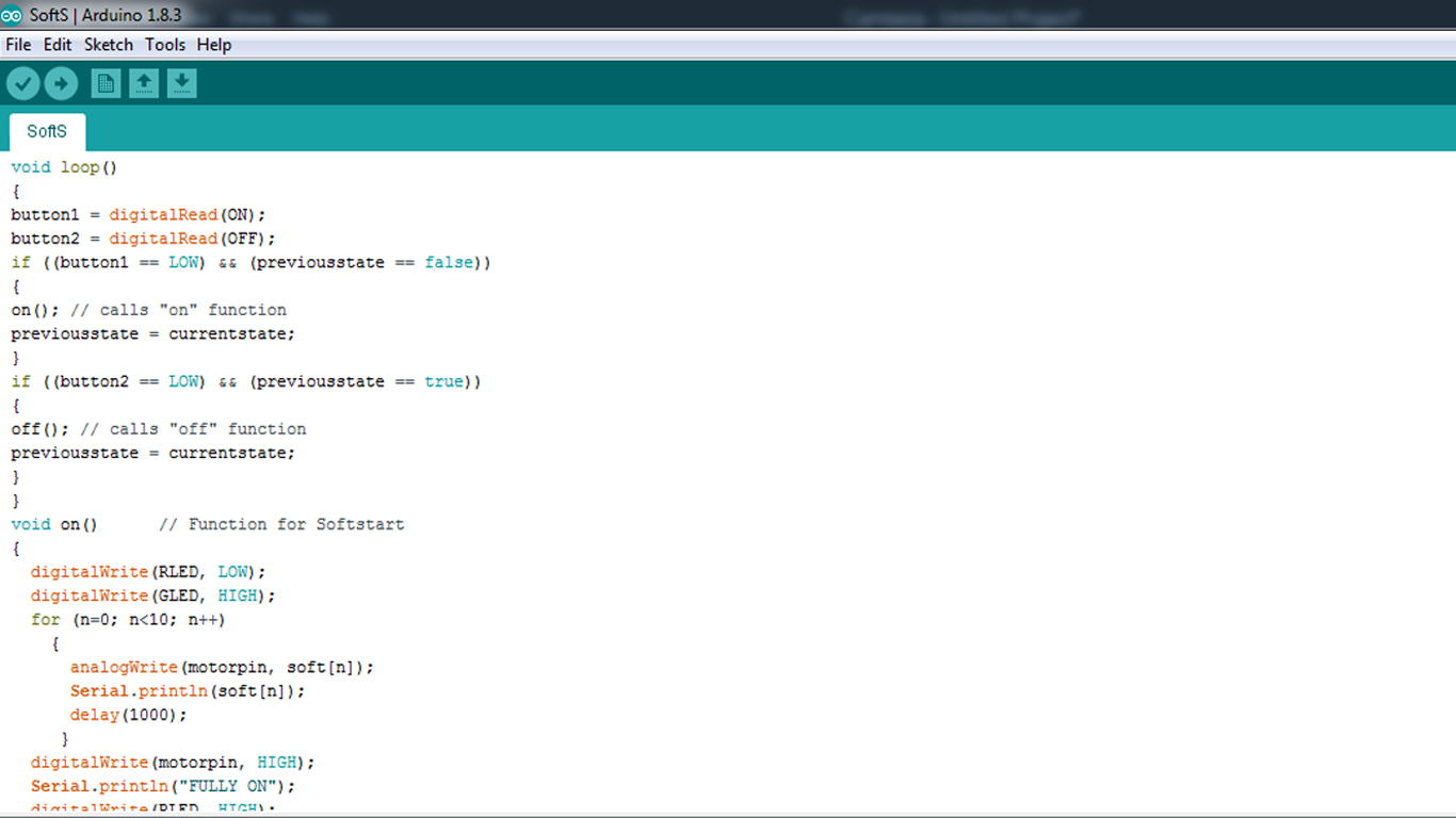
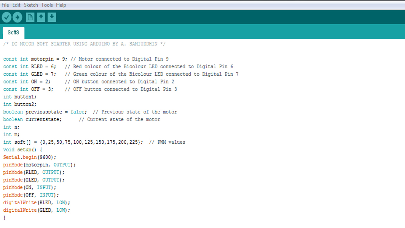
Download the code i have given..
Switch ON the hardware....
In the arduino code, i have transferred the PWM values using for loop.
Downloads
Push to Button to Slow Startup of the Motor
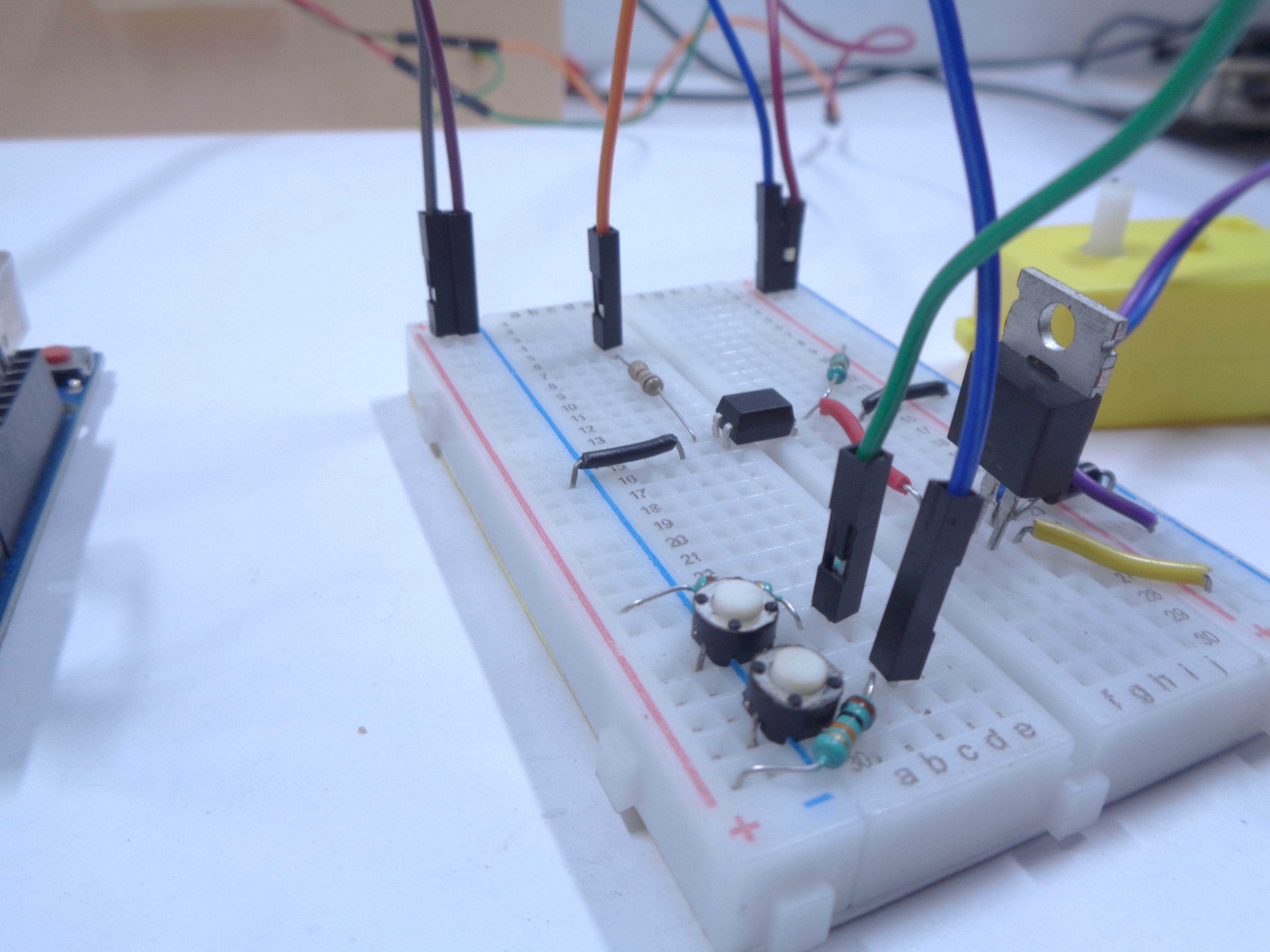
Push to ON button. you can see the motor start up slowly. it will then attain the maximum speed.
If you want to watch a live demonstration click the link below
if you have any suggestion, comment me..