DC Adjustable Power Supply
by jorgeeldis in Circuits > Electronics
459 Views, 4 Favorites, 0 Comments
DC Adjustable Power Supply

An electrical device known as a power supply provides electricity to an electrical load. A power supply's primary function is to transform electrical current from a source into the proper voltage, current, and frequency needed to drive a load. Because of this, power supplies are sometimes known as electric power converters. While some power supplies are integrated into the load appliances they power, others are independent standalone pieces of equipment.
Supplies
- • Transformer
- • Diodes
- • Capacitors
- • Resistors
- • OpAmp
- • BJT Transistors
- • 3D Printed Case
- • PCB
Simulations
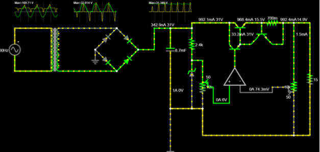
The circuit begins to be designed in a simulation software to be able to understand in an "ideal" way the behavior of the circuit. On this occasion, the falstad software was used, since we feel that it is the most suitable for the experience that we are carrying out.
Breadboard Tests
After simulating the circuit and confirming our values with those calculated, we have to carry out the preliminary test of our project on a Breadboard, with the official components that the teacher gave us, using a filter, rectifier and transformer.

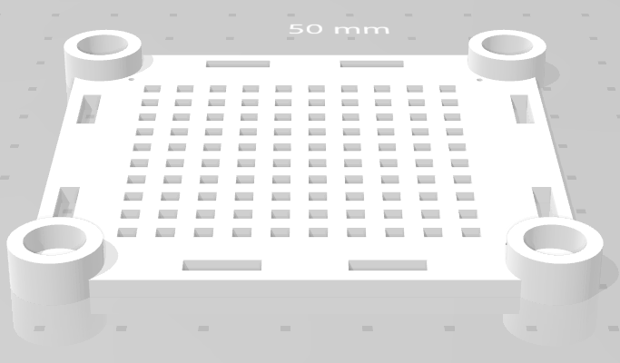
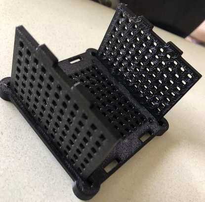
3D Printing a Case
With the components in our hands, it was time to print the box where our PCB will be covered. This design was provided thanks to the professor Clevis Lozano and printed in the laboratory of the Faculty of Electricity.


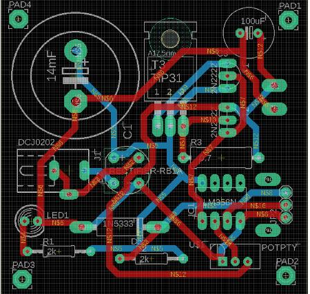
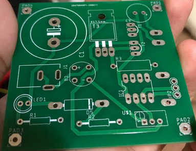
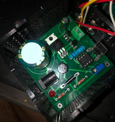
Printing the PCB
After printing the PCB and getting the components we started soldering the components to the board. Our first impression was that it was of good quality and we liked that it was a relatively small board for a source of moderate voltage and amperage. We also have the PCB file in case you want to make future adjustments.
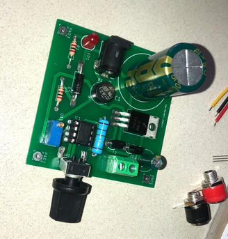
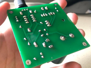
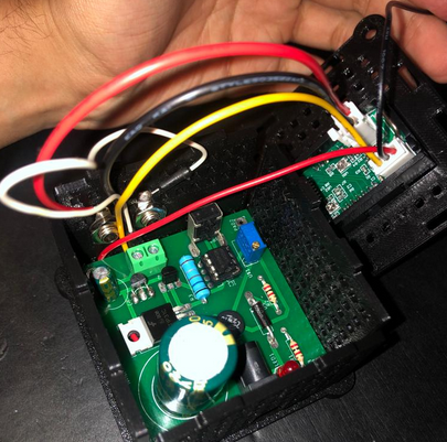
Soldering Components
When we had the opportunity, we soldered the components carefully, first the small components and then the big ones, so they don't cause problems, we took turns soldering, when one soldered the other helped to hold the component and that's how we left.
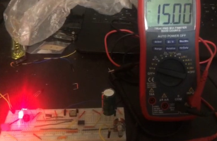
Connection of Multimeter & Final Testing
We will begin to connect the multimeter to our circuit and the outputs in order to connect the load. We are guided by the video given thanks to the teacher for the connection of the multimeter, then we will see a representative circuit.
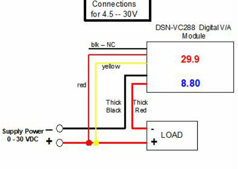
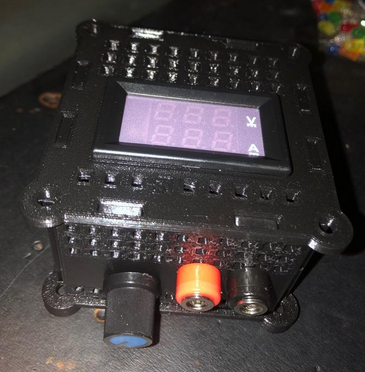
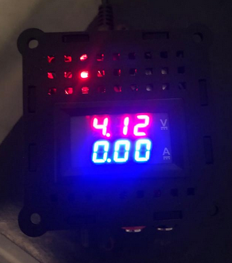

With this last image we can conclude that we successfully finished this project and it works perfectly