Custom RC SBUS Transmitter for ArduRover
by JonathanL178 in Circuits > Remote Control
272 Views, 3 Favorites, 0 Comments
Custom RC SBUS Transmitter for ArduRover

Following on from my initial RC transmitter, I was inspired by the design from https://freeflysystems.com/movi-controller to make my own newer design for the remote controller to pair with my updated RC car (Running ArduRover v4.5.7 - introduction to ArduRover is found at https://ardupilot.org/rover/). This page documents the design process, assembly and testing of v2 of this remote controller, intended to be robust and flexible.
Supplies
Hardware
1 x Panel mount rocker switch SPST https://au.rs-online.com/web/p/rocker-switches/2828232
1 x APEM joystick https://www.digikey.com.au/en/products/detail/apem-inc/HF50S10/5210479
Note - can be swapped for a cheaper Arduino joystick module (https://www.jaycar.com.au/arduino-compatible-x-and-y-axis-joystick-module/p/XC4422?gad_source=1&gclid=Cj0KCQiAvvO7BhC-ARIsAGFyToWwzP-ER1xKkwi4qJURC_tzCTsTpAX5ZLWc78iYVipO7FnLytc7aRoaAg_hEALw_wcB)
OR
FrSky hall effect gimbal replacement (https://www.nextfpv.com.au/products/frsky-m9-hall-sensor-gimbal-for-taranis-x9d-x9d-plus?srsltid=AfmBOoqD4FIb8_YsGzd9L3nc_xIDEvtoZc1Y3PTH0p1pLbproBh-94en) parts as alternatives - with CAD design changes required
1 x STM32F042 Nucleo Board (Nucleo-32) https://www.digikey.com.au/en/products/detail/stmicroelectronics/NUCLEO-F042K6/5428804?srsltid=AfmBOoqa0ZQY6e24hekjTC1um641RTmswCAXaaATIx4pAatBgM8G7yJf
1 x Toggle switch (SPST)
1 x Toggle switch (SPDT)
1 x RFD900x
8 x M3 x 10 screws
11 x M3 x 6 screws
8 x 18mm M3 metal hex standoffs
3 x 8mm M3 nylon hex standoffs
1 x Android phone with QGC installed
1 x FTDI 3.3V or 5.0V cable
Jumper wires
Power bank (5V 2600mAh minimum)
Laptop with Mission Planner (optional)
Circuitry
3 x Resistor 1kohm
1 x Resistor 300ohm
1 x Resistor 10Kohm
1 x 2N700 NPN Transistor
1 x 3mm through-hole LED
1 x perfboard
6 x right-angle male headers
1 x soldering iron
1 x solder lead
Transmitter - Mechanical Design and Assembly


The major design requirements for this redesign of the transmitter were:
- Ergonomic but sturdy and rigid enough to hold power bank battery and joystick IO
- Minimal 3D printed parts
- Possible to add more user interfaces (ie - more switches, knobs, sliders in future)
- Compatibility with ArduRover input channel requirements
- Easy access for wiring routing and changing out plates (used standoffs)
- Each plate is 2mm thick with 40% infill (HIPS filament)
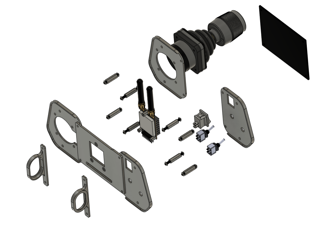
The various plates were as follows:
- LH Top Plate - switch and io panel mount
- LH Top Plate - for switch plate rigity (duplicated)
- RH Top Plate - for joystick panel mount
- RH Mid Plate - for joystick plate rigidity (same dimensions but with wire cutout)
- Rear Plate - holds RFD900 and Battery bracket
Transmitter - Electronics Design

The interfaces and circuitry was based around the STM32 F042 chip. The use of through-hole resistors and passive components made it easier to assemble and debug without the need for a physical PCB to be manufactured and assembled (possible future work as well)
As seen in the schematic:
- SBUS serial inverter circuit
- ADC interfaces for the two axis gimbal
- LED for debugging
- Pull-up resistors for the toggle switches
- 5V direct from power bank
Transmitter - Software
The main example code I found was provided at https://quadmeup.com/generate-s-bus-with-arduino-in-a-simple-way/. The IO was modified to suit my joystick and I added in simple functions for flight mode switch logic and an auxiliary switch as required by Ardupilot for ArduRover basic setup
Downloads
Assembly Instructions


- The perfboard was secured to the top RH and top LH plates with M3 x 10 screws
- Standoffs ensure rigidity between the lower RH and lower LH plates. Assemble the two plates to the standoffs using M3 x 6 screws on both sides
- The RFD900 radio was fastened to the rear plate using the nylon standoffs and the same M3 x 6 screws
- The rear plate was secured to the bottom end of the main standoffs using the M3 x 10 screws
- The joystick is secured to the top RH plate with the provided screws
- Fasten the toggle switches with the hex nut and washer, inserting from below
- Insert the rocker switch to the top LH plate which is push-fit
- The battery slots into the two sides of the battery brackets (should be secure fit)
- FTDI cable between RFD900 (USB-A male) connects into laptop (to give telemetry)
- See the exploded view and CAD of assembly for more details
Field Testing With ArduRover
The transmitter was brought out to the local park to test out driving the ArduRover in manual mode and to check the live video stream. Once the vehicle was powered on and received enough satellites, it was 'armed' and I could then drive it around the park in manual mode. Run time on one 2S 2200mAh lipo was about 10 minutes.
Telemetry Connection Steps:
- Power switch on ArduRover is turned on
- Connect FTDI from RFD900 to laptop running QGC or Mission Planner
- Connect in top right corner with required COM port and baud rate (115200 baud rate is the RFD900 setting I used)
- Arm the rover by setting the arm switch to HIGH
- Steering and throttle will be enabled
Video Stream Connection Steps (optional):
- If live stream from Picamera is required, connect to the wifi-hotspot of the Rpanion server running on the Pi
- Navigate to http://10.0.2.100:3000. and copy the MissionPlanner Gstreamer link to Ground Control software - Video Settings
- Video will appear on the main HUD
Future Work
Future work will involve:
Tuning - as per https://ardupilot.org/rover/docs/rover-tuning-process.html
- Tuning the Speed and Throttle controller
- Tuning the Navigation controller
Missions
- Testing out simple autonomous missions
- Adding in computer vision to detect an obstacle or object during mission