Cribbage Board
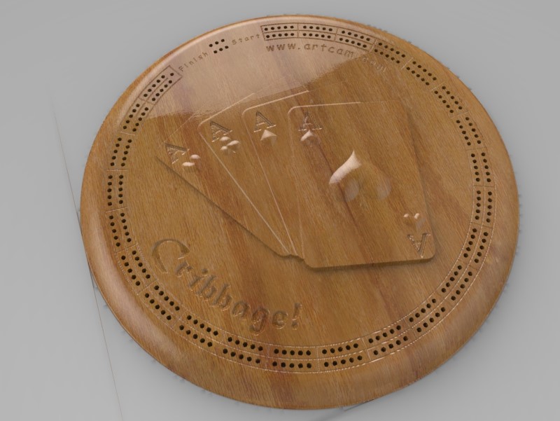
This is how to create a custom cribbage board on a cnc machine using ArtCAM Express software.
Things you will need
· ArtCAM Express
· CNC machine
· Block of wood
Watch the Video
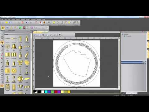
Creating a Base
1. Determine the size and shape of board you want.
2. Open a new model to these dimensions (for this example 400 x 400 x 25 mm).
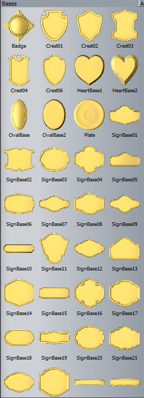
3. Open the clipart library and select an appropriate base to import.
4. Resize, centre and change the z range of the base to 15 mm before selecting paste, ensuring that the “paste outline vector” box is ticked.
Creating the Track
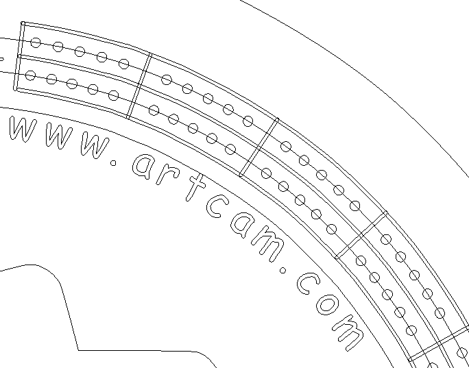
1. In the 2D view, centre three circle vectors of diameter 330 mm, 350 mm and 3 mm.
2. Select all three circles and use the “paste along a curve” tool to make 160 copies.
3. Ungroup the copies and delete every 6th circle on the guide tracks until there are 120 holes on each.
4. Delete the excess circles leaving a winning hole and a few extras like so:
then group all remaining small circles.
5. Offset the outline vector inwards by 20 mm, 30 mm and 40 mm.
6. Using the “node editor” tool hover over the line and press “C” to cut these vectors at the start and end points of the track. Delete the cut vectors.
7. Offset each of these vectors by 0.5 mm to both sides and delete the original vectors. Group these three vectors together.
8. Use the “create a polyline” tool to create a straight line between two of the sections of track. Use the transform tool to position the vector origin at the centre of the model, then holding control, click and rotate the vector about the origin to separate each track section. Group these vectors.
Adding Decorations
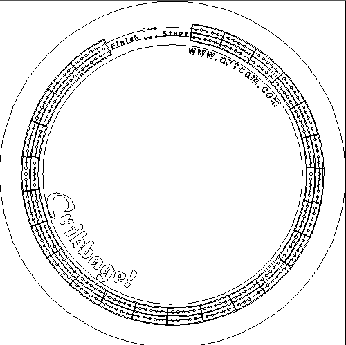
1. Choose a relief from the clipart library and position it in the centre of the board. Change the z range to 10 mm
and ensuring the add icon is showing, select paste.
2. Select the “text” tool and click within the model to add text. The size and font can be changed in the right sidebar.
3. Offset the outer vector 50 mm inwards.
4. Open the “wrap text to curve” tool, highlight the text and circle vectors and press select.
5. Choose a text position and drag the text to the desired position.
6. Add any extra decoration and text the same way.
Generating the Toolpath
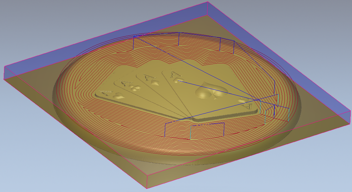
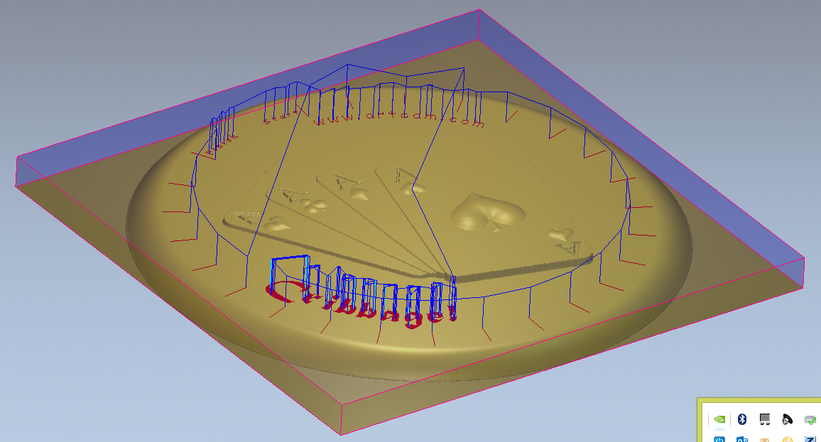
1. Within “Toolpaths” in the project tree, select the outline vector and create a profile toolpath around the outside of the selected vector with a start height 0 mm and end height 25 mm. Select an appropriate tool and then calculate.
2. Select the outline and cards vectors and create an area clearance toolpath inside the vectors. Select roughing and finishing tools and a finishing depth of 10 mm.
3. Selecting just the cards vector, create a 3D machine relief toolpath within the selected vector.
4. Create another 3D machine relief toolpath between the outside and cards vectors.
5. Selecting the track outline and all text on the model, create a v-carve toolpath with a start depth of 10 mm and use the small v-bit tool.
6. With the holes vectors selected, create a drilling toolpath using a 3 mm tool and a start and finish depth of 10 mm and 20 mm respectively.
Simulating the Toolpaths
1. Select “Toolpaths” on the project tree, then select “Simulate Toolpaths” .
2. Remove the excess material by right clicking on “Simulation” and selecting “Delete Waste Material”, then click on the waste material.
3. Change the material by clicking on “Simulation” and then selecting an appropriate material.