Credit Card ATtiny Game Console
by cheungbx in Circuits > Arduino
5721 Views, 11 Favorites, 0 Comments
Credit Card ATtiny Game Console
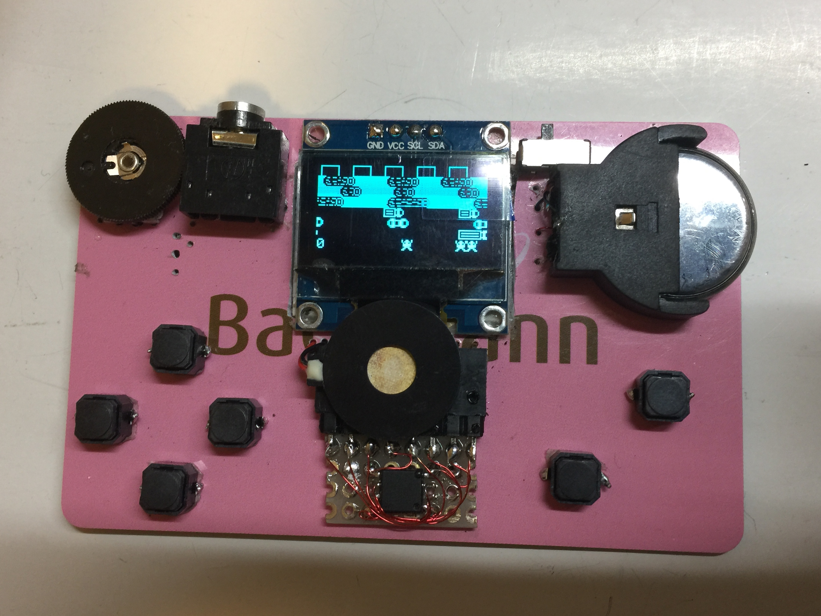
This is the instructions to build an Attiny 85 game console built on an expired credit card.
A demonstration of the finished product can be found in this youtube link:
gametiny on a real credit card.
---------------------------------------------------------------------------
I was inspired by the mini game consoles based on the energy efficient ATtiny85 MCU.
There are several retro-game console designs: The Attiny Joypad created by Daniel Champagne.. (Electro L.I.B) 2018 GPL V3 is a great platform with the 4 way directional buttons/joystick and another fire button . The other platform called Attiny Arcade created by webbloggles is also a great mini game console with the simplicity of having only two buttons. Both platforms inspired me to create something taking the best from both worlds.
This version of the game board I called “gametiny” is based on the Attiny Joypad created by Daniel Champagne. I modified it to add a header for USBasp programmer that doubles up as a socket for the game cartridge which contains an ATtiny85 chip. You can make a few game cartridge and load up your favourite games so you can swap the games on your trip. The ATtiny85 is very energy efficient. You only need one CR2032 cell battery to play games for hours. Besides the A button which is usually used as the fire button, I added a B button to pull PB3 to ground. This allows the interrupt codes to work for both PB1 and PB3, making it easier to convert games written for the Attiny arcade to work on Attiny joypad.
Links
Original Tiny Joypad design by Daniel Champagne.
https://sites.google.com/view/arduino-collection
Original Attiny Arcade keychain kit
http://webboggles.com/attiny85-game-kit-assembly-instructions/
Arduino board driver for attiny85
https://raw.githubusercontent.com/damellis/attiny/...
schematics and source codes in https://github.com/cheungbx/gametiny
Get the Parts
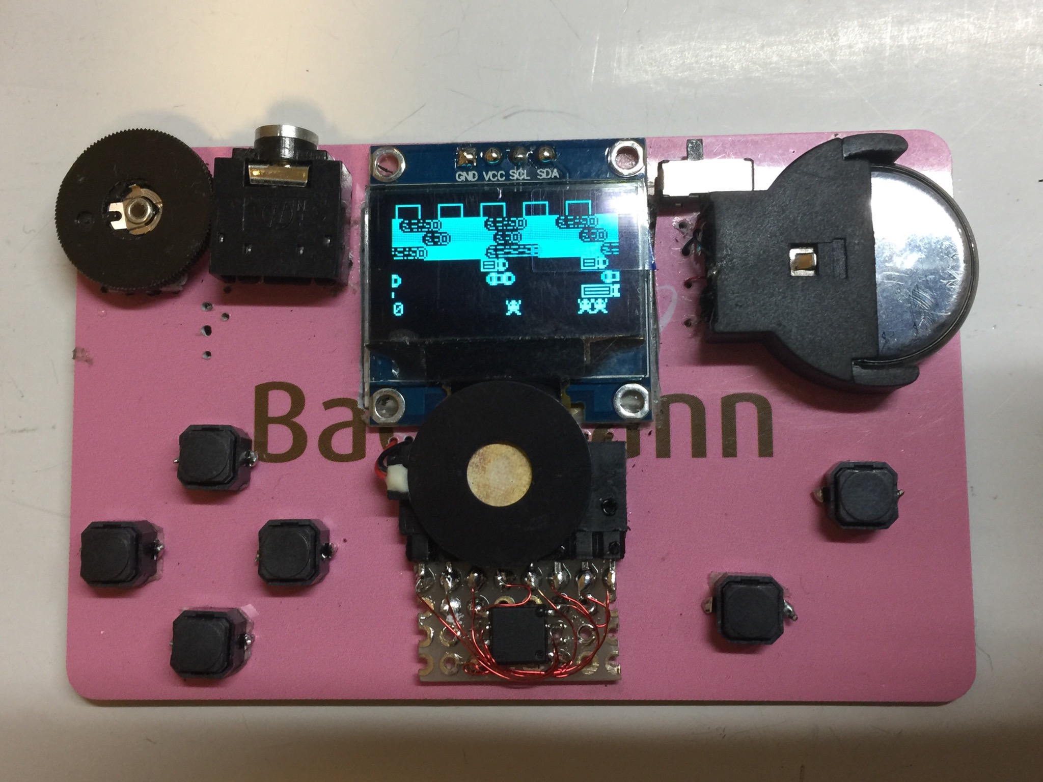
1. For each game cartridge,
one ATtiny85 SOD-8 (surface mounted), one small single sided perf board (prototype board), one 8 pin male header.
2. 0.9” I2C Mono OLED (with embedded SSD1306 controllers) on 4 pins (GND, VCC, SCK, SDA).
3. CR2032 3.3V Lithium cell battery.
4. Battery holder for CR2032.
5. mini piezo sound unit.
6. 3.5mm headphone jack with switch
7. 6 silent buttons
8. mini 10K VR for volume control.
9. 8-pin female header for connecting to game cartridge.
10 Mini Slide switch for power button
11. 2 expired credit card or paper/plastic boards of the same size.
12. 0.2mm or 0.3mm laminated (insulated) wire
13. USBasp programmer.
14. 8 core ribbon cable.
15. 8 pin female header and 2x4 pins female header for the programming cable.
Make the Main Board.
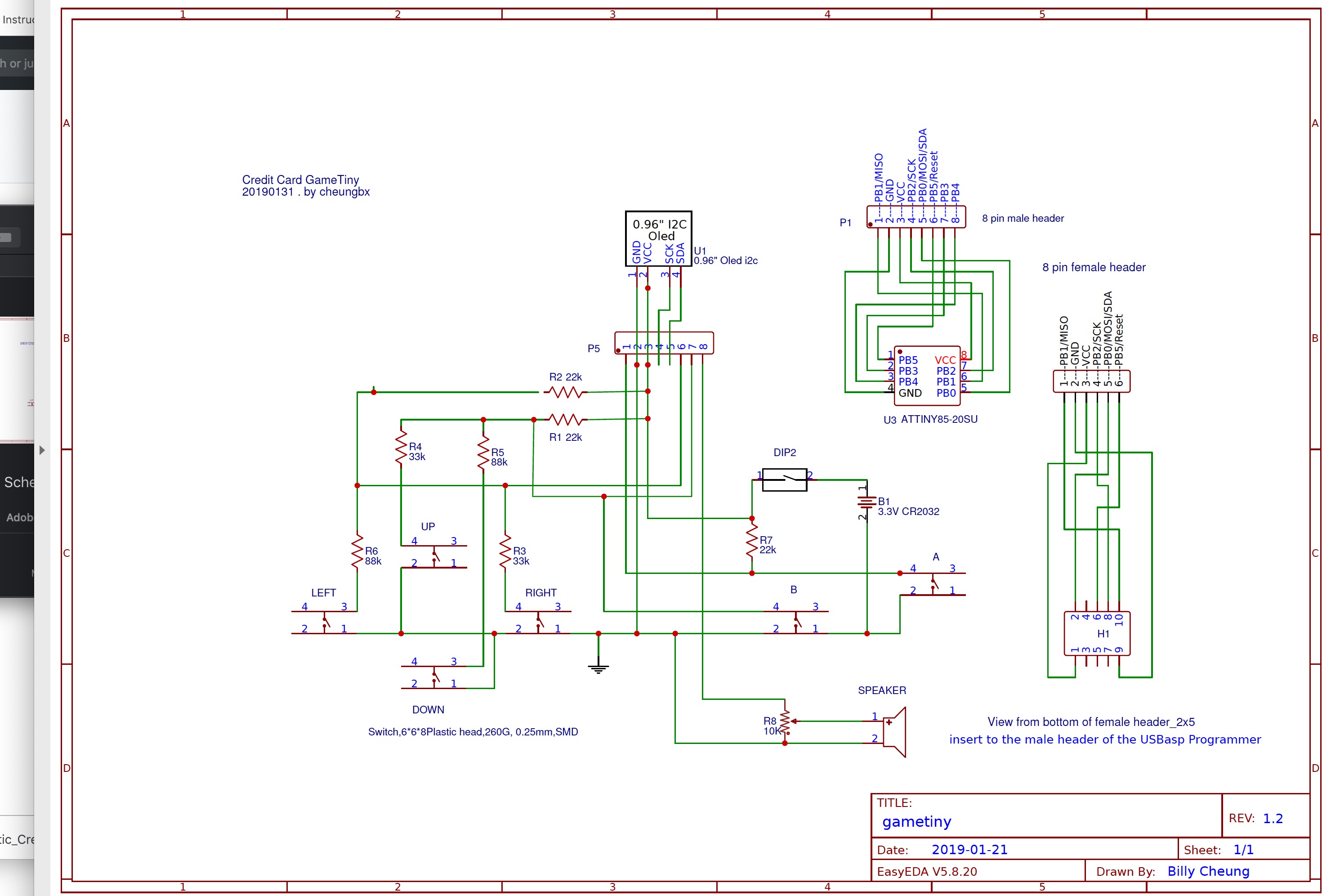
This project uses an expired credit card as the frame. You can also use cardboards or plastic boards.
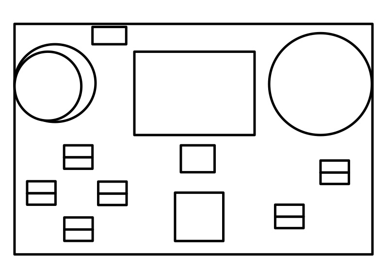
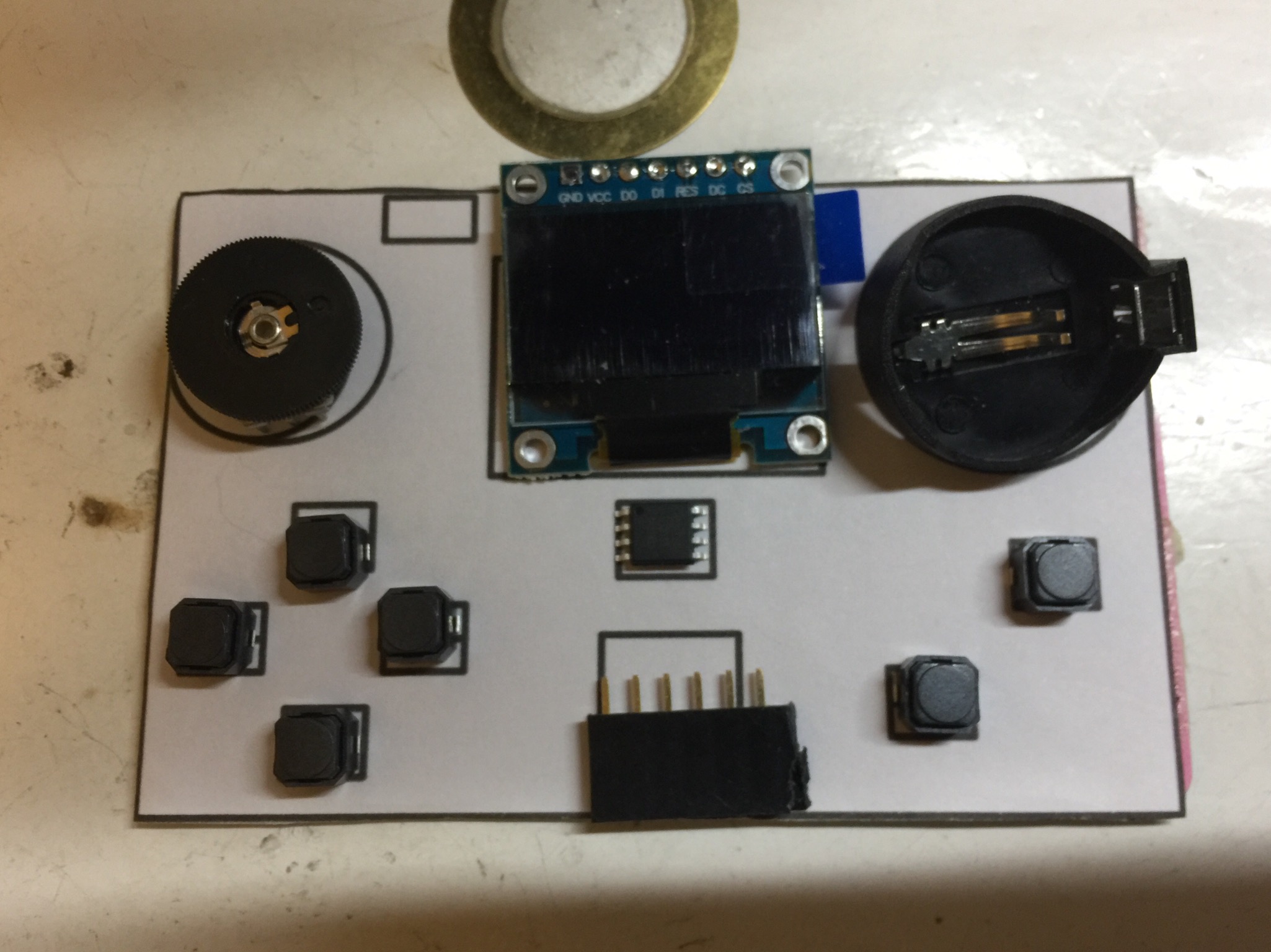
Design the layout of the buttons on the power point. Print out the power point to paper with the actual size. I used the print settings of two slides on one page to shrink it to actual size. Stick the layout onto the credit card using double sided tapes. Drills holes using 0.5mm drill pits on the marked points for the pins of the buttons and other components to be mounted onto the credit card. Solder short wires onto the two side of each silent button so they can be inserted into the credit card. There are the D-PAD buttons for up, down, left, right, and the fire buttons (A and B). Insert the buttons and other components onto the credit card. For components with longer legs, e.g. the buttons, bend the legs in opposite direction to hold it in place. Otherwise, use double sided tapes or glue to hold the components in place. Wire up the circuits using 0.3mm laminated (insulated) wires according to the circuit diagram. To keep the main board as thin as possible, the OLED is soldered directly to the wire instead of using male header pins. An 8 pin female header is used to connect to the game cartridge that is actually a surface mounted Attiny 85 micro-controller.
Cover the wires at the back with a second credit card.
Make the Game Cartridge
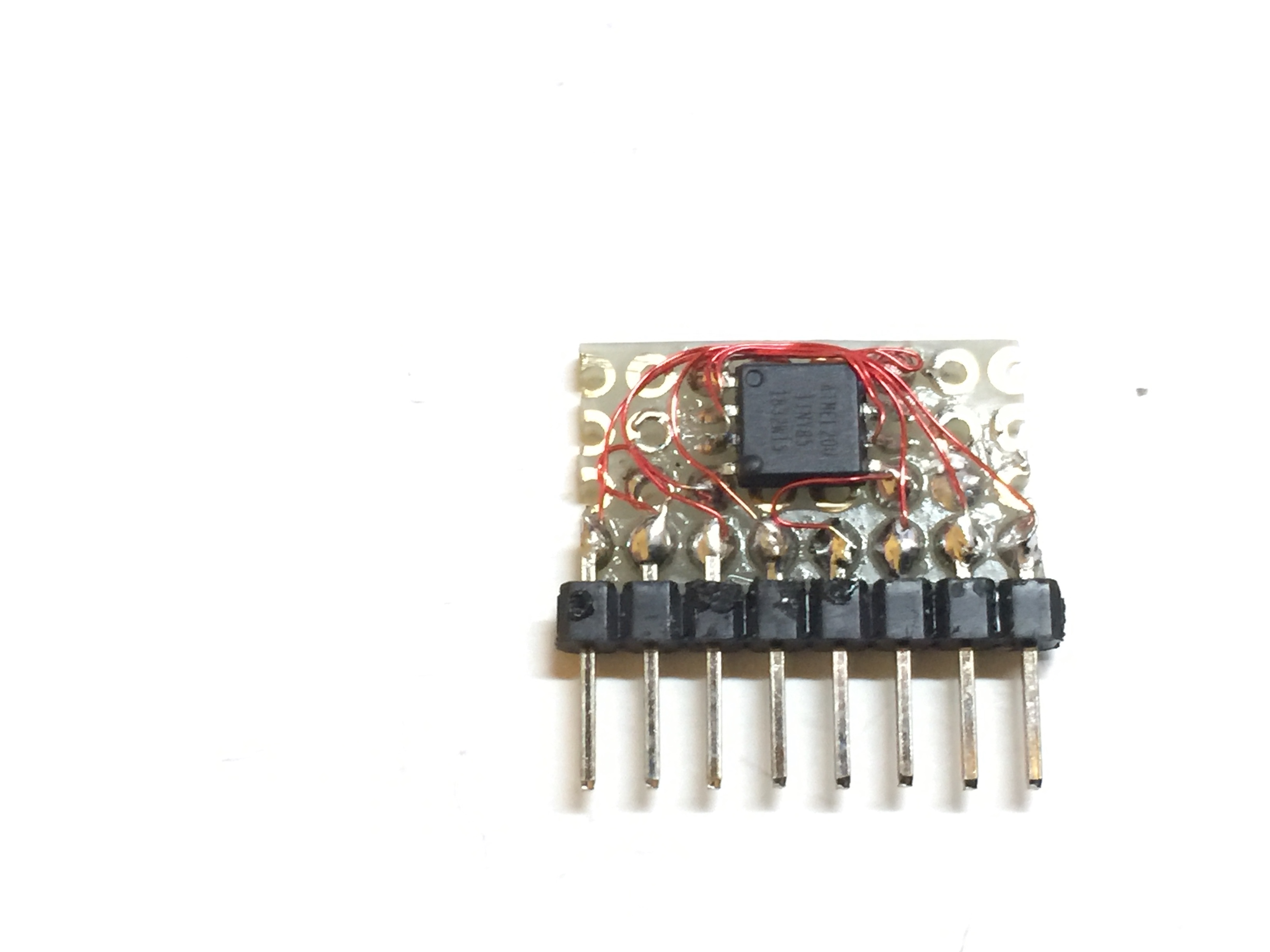
1. Cutout a small perf board that can accommodate 4 rows of 8 holes
2. Use a cutter to split the 3rd row into two disconnected half (for the middle two pins of the Attiny 85 to stand on).
3. Solder the ATtiny85 SOD-8 (Surface mounted) onto the board.
4. Solder an 8-pin male header onto the first row.
5. Wire up the cartridge according to the circuit diagram using 0.3mm laminated (insulated) wires.
Load Games Into the Cartridge.
1. If you are new to Arduino, download arduino from arduino.cc . Click Software. Click Download. Then select the version for your PC or Mac. download and install.
2. browse to https://github.com/MrBlinky/Arduboy-homemade-package and follow the instructions there to add the board definition and libraries for for home made Arduboy and Flash cart support. I will summarise in the following steps:
3. Start Arduino IDE. Click Preferences from the Arduino top menu. Input this text into the “Additional Boards Manager URLs” https://raw.githubusercontent.com/damellis/attiny/ide-1.6.x-boards-manager/package_damellis_attiny_index.json If you already have other text on the field, insert this additional text at the beginning, then add a “,” and keep the other URLs already there intact.
4. Exit Arduino IDE and start the IDE again to take effect of the change above.
5. Click Tools -> Board: -> Board Manager. Enter “Attiny” to search. Select to install the latest version of Attiny board driver. The package will be added to Arduino.
6. Now select Tools-> Board: “ATtiny 25/45/85”
and select the following parameters :
Processor: Attiny 85
Clock: Internal 8Mhz (only for Pac Man game, choose Internal 16Mhz)
Programmer: USBasp
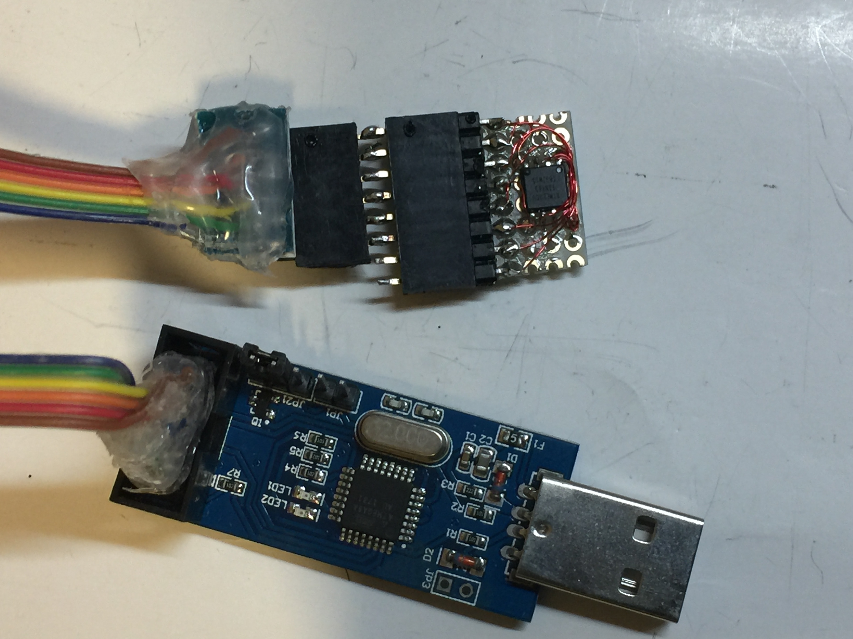
7. Get the USBasp programmer, switch it to 5V (instead of 3V). Connect the USBasp programmer to the USB port and connect the ribbon cable to the programmer. Connect the other end of the ribbon cable with the 8 pin female header to the male header of the game cartridge (with the Attiny 85 chip soldered onto it).
8. Click “Burn Bootloader” to burn the fuse to the Attiny 85. Check the output that it’s successfully completed.
9. From Arduino IDE, open the source code of the game into Arduino IDE . Refer to my GitHub link here: https://github.com/cheungbx/gametiny
10. Click “->” to compile and upload the game through the USBasp programmer to the ATtiny85 chip on the game cartridge. Check that the upload is successful.
11. Insert the game cartridge to the main board. Turn on the game board using the slide switch and start playing.
12. Most of the games are written in a way to go to sleep mode after game is over. To wake it up, just press either the A or B button.
13. If the buttons or sound output did not work, load the “Attiny Tester” to test if the values of the buttons changed correctly when buttons are pressed and released and that you heard beeps when you press any buttons. Double check and fix any soldering or wiring issues.