Creating a Custom-sized Box for 3D Printing With OpenSCAD
by hansamann in Workshop > 3D Printing
23007 Views, 96 Favorites, 0 Comments
Creating a Custom-sized Box for 3D Printing With OpenSCAD
.jpg)
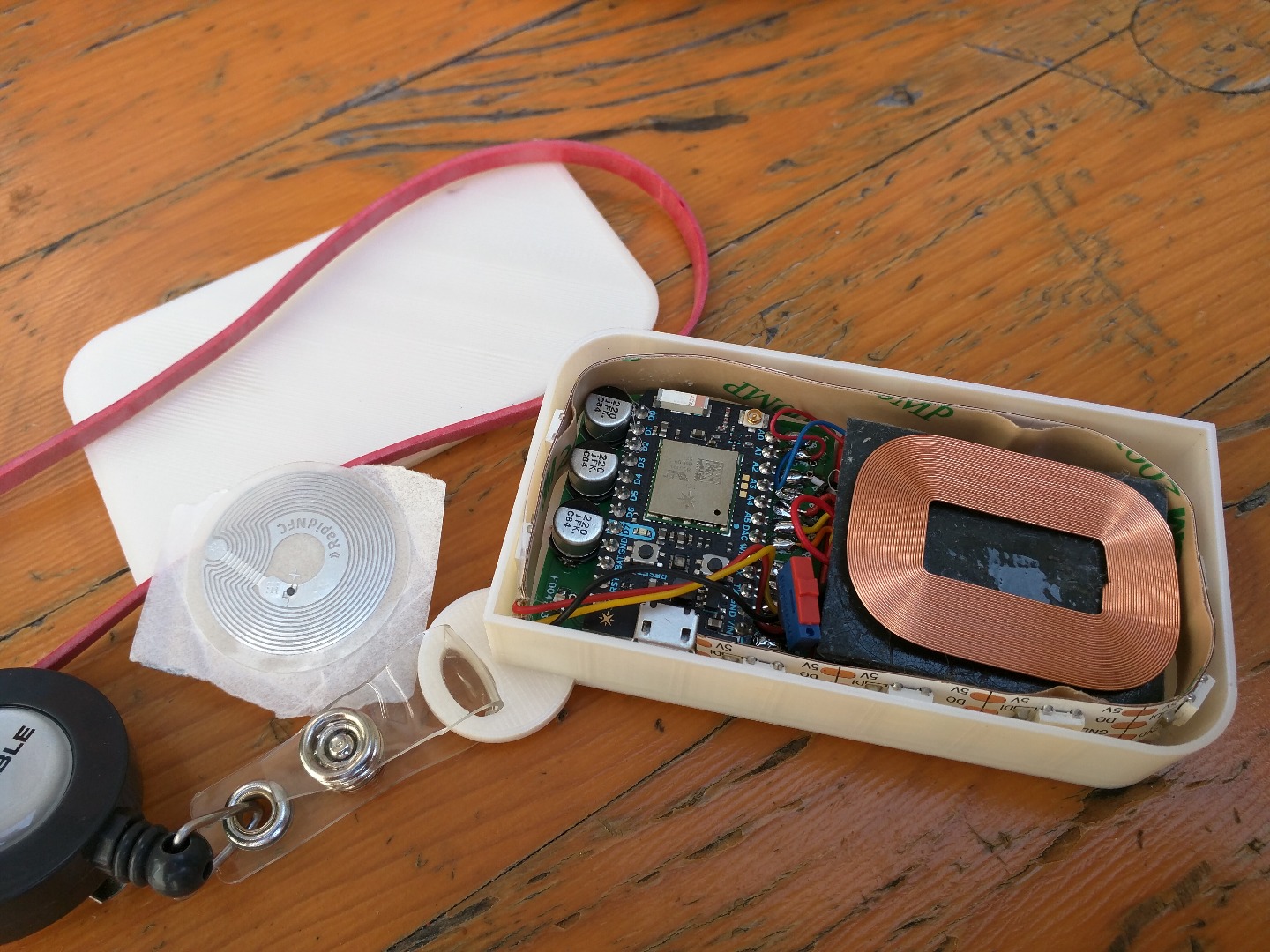
At hybrislabs, we've explored IoT quite a lot and at some point our prototypes became so small and integrated, that we had the need to create custom boxes for these. We initially used 123D for the creation of the STL files for 3D printing, but found this solution way to inflexible (here's the full reasoning). So finally, we came to explore OpenSCAD, a free & open source tool which allows you create STL files for 3D printing and 3D models in general programmatically.
The OpenSCAD language is simple and concise, it took me half a day to get familiar with the basic concepts and another half day to turn our design into a fully parameterized model.
This instructable shows you how to develop this box step by step. Understanding the steps will probably help you to make your own custom design along the way. It should be fairly simple to turn it in to a fully rounded box or add a few more non-rounded sides to it. If you're just interested in the exact OpenSCAD file itself, forward to the last step and download the final step file.
So, let's start with the basic shape for our box...
Understanding Minkowski
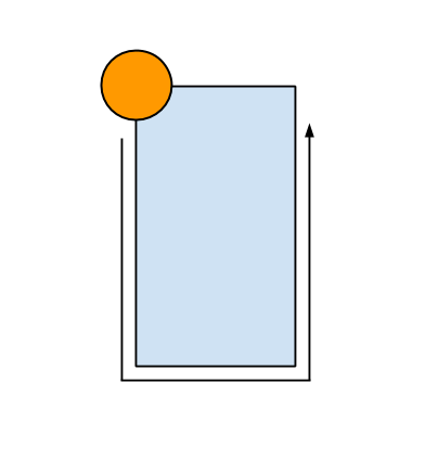
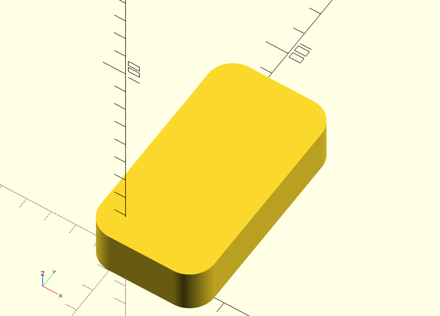
For the box shape, I wanted to have a semi-rounded box with two round "edges" and two normal 90 degree edges. To begin, we have to understand the Minkowski function as it is key to understanding round "boxes with rounded edges".
If you take a look at the uploaded image you can begin to understand how minkowski works. You take a basic, 90 degree model, like a cube, and a round model like a cylinder. The shape of the circle is moved once around the outer edges of the cube, resulting in a rounded box.
At this step, we also defined a few parameters like the width, height, length of the box. The corner radius of the box is defined as well and it's important to understand that the double radius needs to be subtracted from the width and length of the box. That's simply because our round shape wiht corner radius X is going around the cube shape, resulting in a bigger shape in the end.
Downloads
Creating the Basic Box Model and Translating It to the Origin
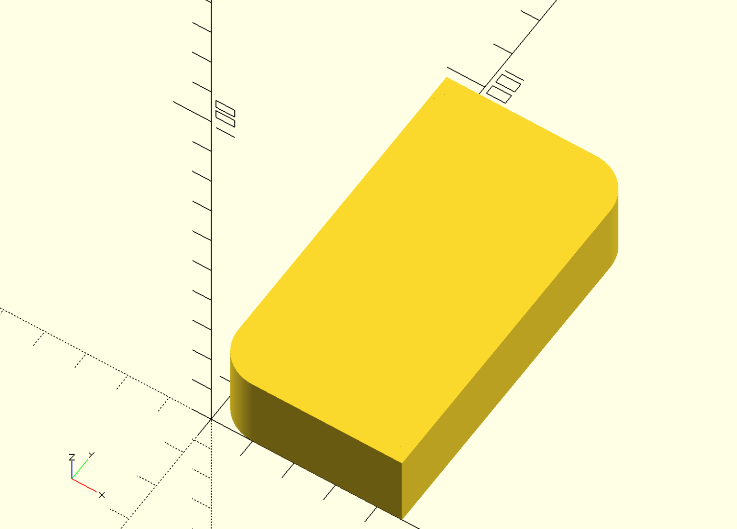
Now that we have a basic step and specified a few parameters, we immediately put "module" definition around it, so we can reuse it easier later on.
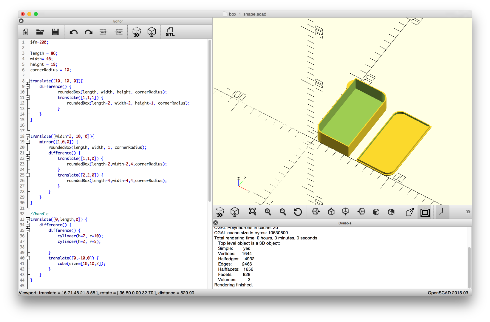
We also add two cubes to the bottom right and top left side of the existing model. Whenever you add things in OpenSCAD which intersect with others, the automatically become one shape, e.g. are combined. Because our model would now be not sitting directly on the origin x/y, we translate to back to the origin.
Downloads
Cutting the Box - Understanding OpenSCAD Difference()
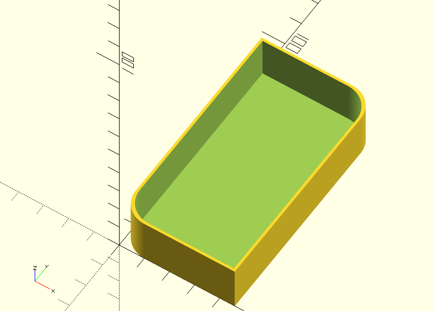
We now have a filled, semi-round box, which is already nice. But to put stuff in, we need to create walls and open it up at the top. This works by creating a second, smaller box and placing it inside the first one. Then we use the OpenSCAD function difference() which cuts out the first model with the second that we placed inside.
One important part of this step for your understanding is the wall thickness and the resulting translation of the inner box, that gets cut out. Because we made the inner box 2mm smaller and translate it by 1mm in both the x and y direction, we get a 1mm wall thickness.
Downloads
Creating the Lid
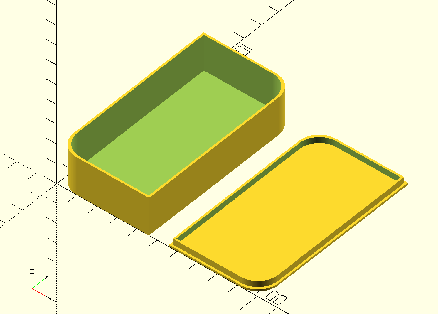
To close it, we'll now model a lid. Technically, ist a model in the shape of the previously created box with an added wall in the center. As our outer box wall is 1mm strong, we have to reduce the width of the inside box by 2 mm. We also translate that shape to the right side of the box.
Because we have to 3D print the lid, we want to have a filled, solid shape at the bottom. That's why use the mirror function to turn around the bottom shape.
Downloads
Finally, a Handle
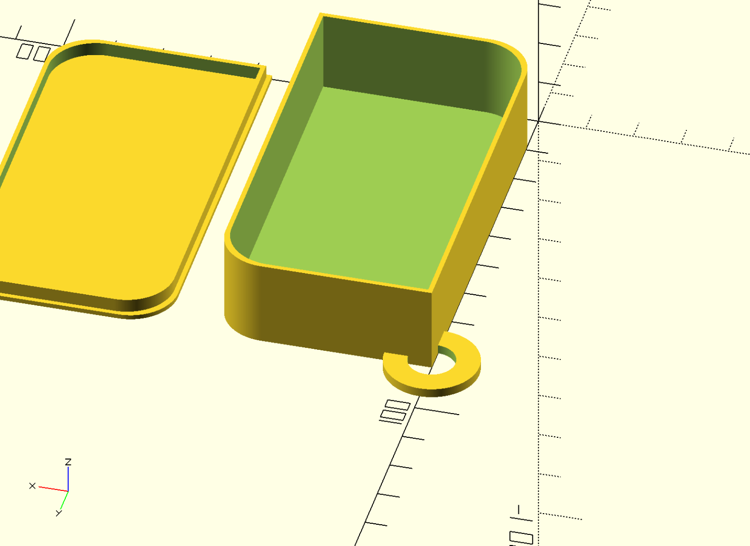
Finally, we required to have a handle. That's technically two cylinders, one cuts a hole into the other. To be able to add it to one of the 90degree sides of the box, we then intersected it again with a cube, which has a 90degree corner. We then move it in place and - voila - we got a fully parameterized box for 3D printing.
I hope you enjoyed the tutorial or simply find the SCAD file useful - please share it & customize it!