Creating a Soft Circuit Project With SnapNsew
by MakersBox in Circuits > Wearables
4562 Views, 34 Favorites, 0 Comments
Creating a Soft Circuit Project With SnapNsew
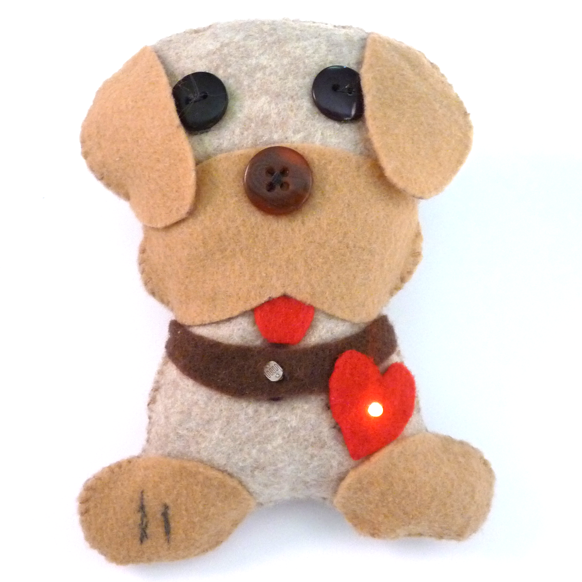
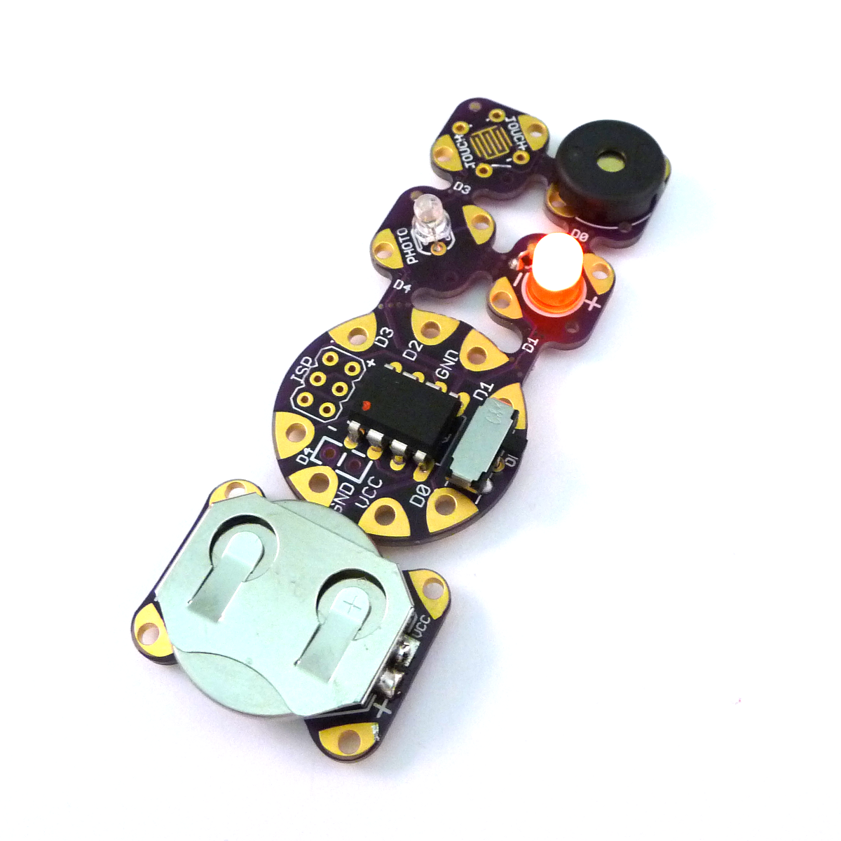
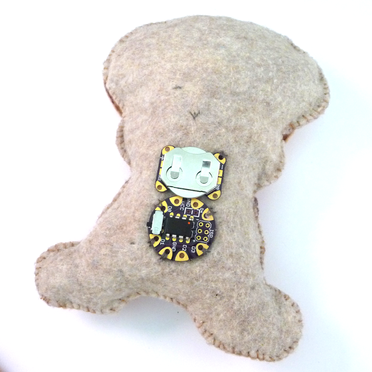
Embedding electronics into textiles is an exciting way to get kids interested in electronics. Unfortunately, the techniques necessary to create a robust project are not trivial. I've created this system which allows you to:
- Easily create and test a working microcontroller circuit with basic inputs and outputs using standard through-hole components and a printed circuit board.
- Snap the pieces apart and easily sew them into a soft circuit project.
This Instructable will cover sewing the circuitry into a felt toy as an example. This just scratches the surface of possibilities. Bracelets, bags, hats. Check out the imaginations at work at my last workshop
For building and testing the electronics, see the previous Instructable: https://www.instructables.com/id/SnapNsew-An-Educational-Soft-Circuit-Platform/
A kit for the electronics and conductive thread is available at Tindie.com.
Supplies and Template
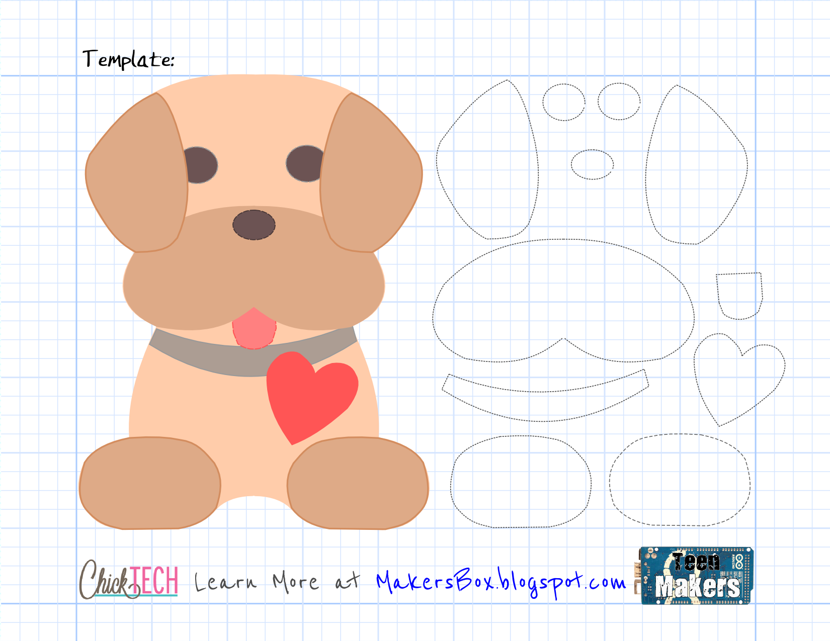
A kit for the electronics and conductive thread is available at Tindie.com, or see previous Instructable for creating the electronics portion.
You will also need:
- Felt.
- Scissors.
- Hot-glue gun and glue.
- Polyester stuffing (or scrap felt pieces).
- Thread or embroidery floss.
- Buttons or other craft embellishments.
- Patience.
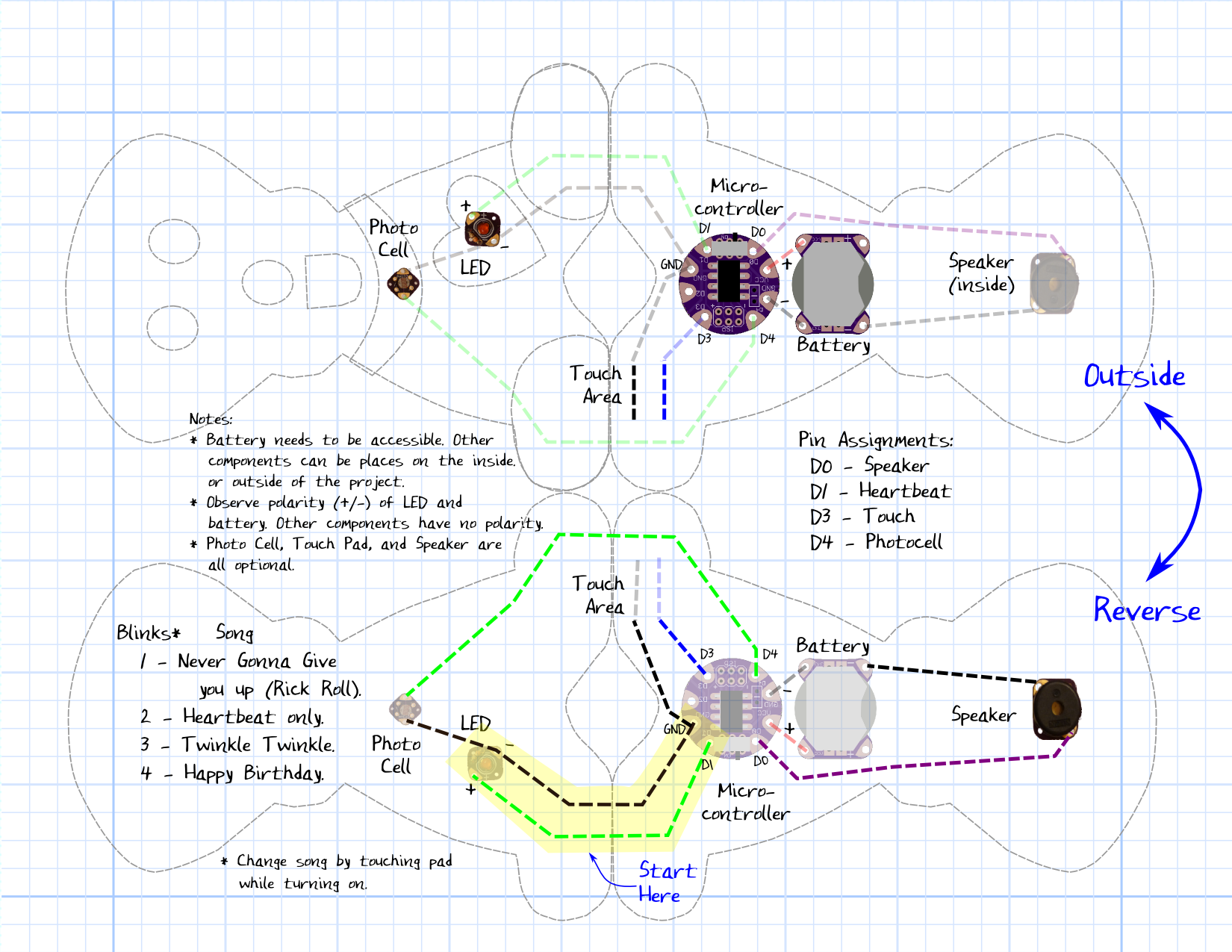
All good project starts with a plan. It is far easier to change ideas when they are in pencil that after the stitches have started flying. I'm providing you with a detailed plan of both the circuit layout and the craft portion. Deviate at your own risk!
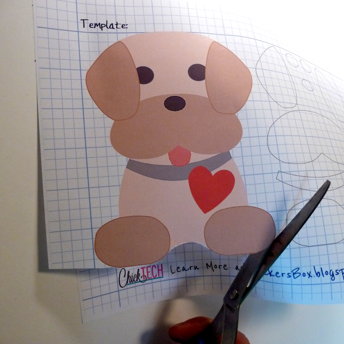
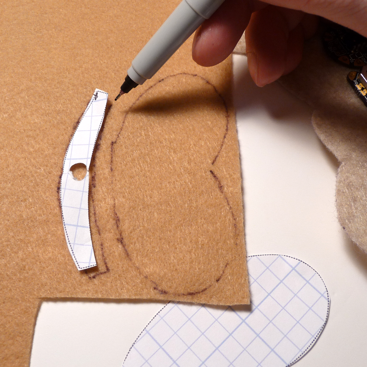
- Print and cut out the attached template as shown in the first photo.
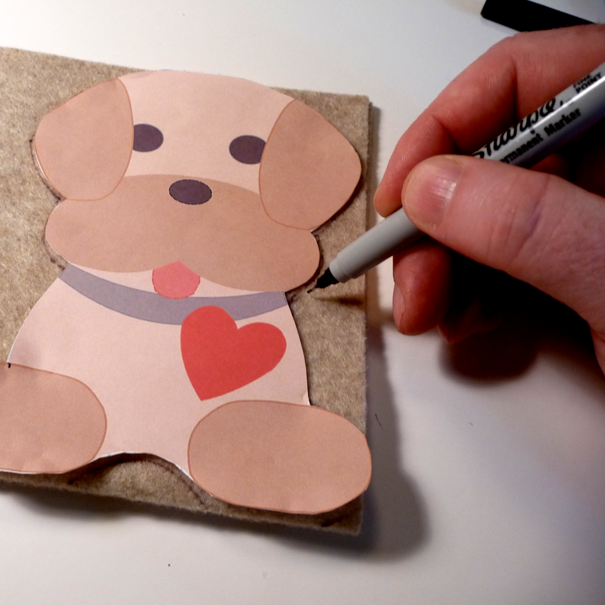
- Trace the template on to a folded piece of felt so that the fold is at the feet.
- This is important because we are going to sew electrical traces across the feet. You can sew them together with regular thread if want different colors for front and back.
- I use sharpies, which won't show if you reverse it before sewing. You can also use tailor's chalk or pencil.
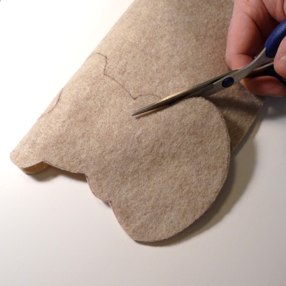
- Cut the pattern from the felt. A good pair of scissors is worth its weight in gold.
Stick Me
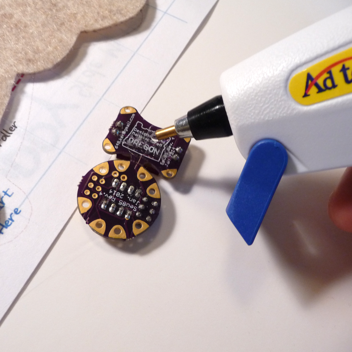
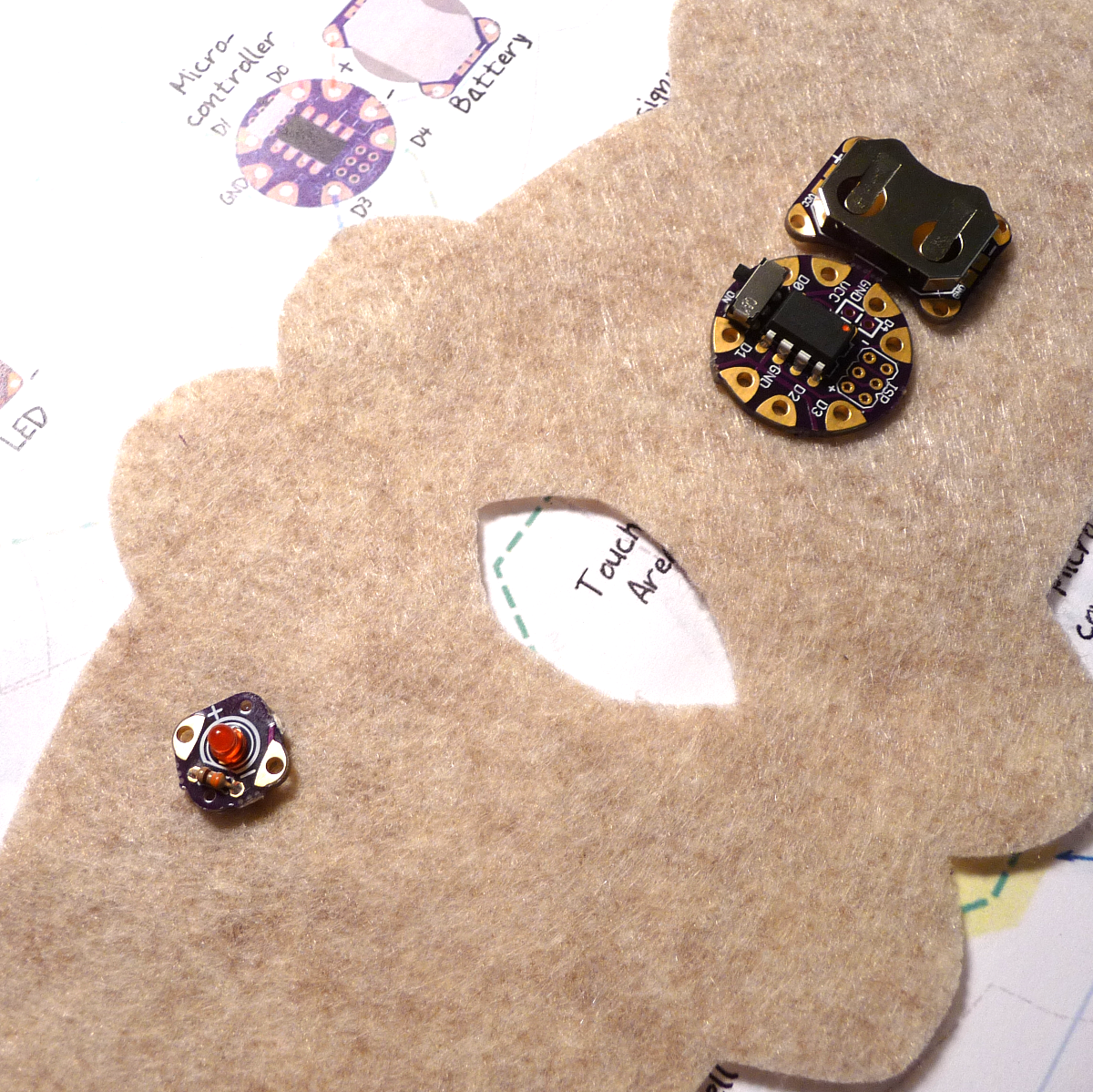
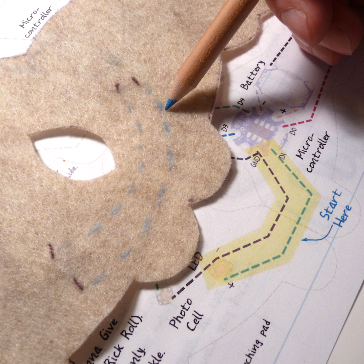
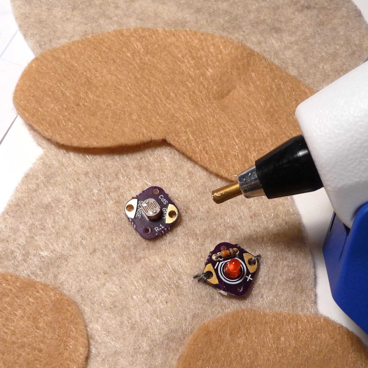
I like hot gluing the components in place and then stitching them. The only drawback is that hot glue is very hard to stitch through if you get it where the eyelets are. Use sparingly as we a just trying to tack components in place. The stitching with secure them later.
We are going to do one component at a time so we can test as we go. Start with the microcontroller and LED.
- If not already separate the components of your SnapNsew.
- Keep the battery and microcontroller together saves you some stiches if it fits your plans.
- If you have difficulty breaking the boards apart, wire cutters can be used where the perforations are.
- With a small amount of hot glue, place the microcontroller and LED in the appropriate spots, ensuring their orientation matches your plan.
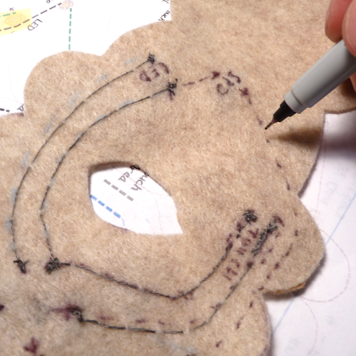
- Mark where your traces will be stitched.
First Knot
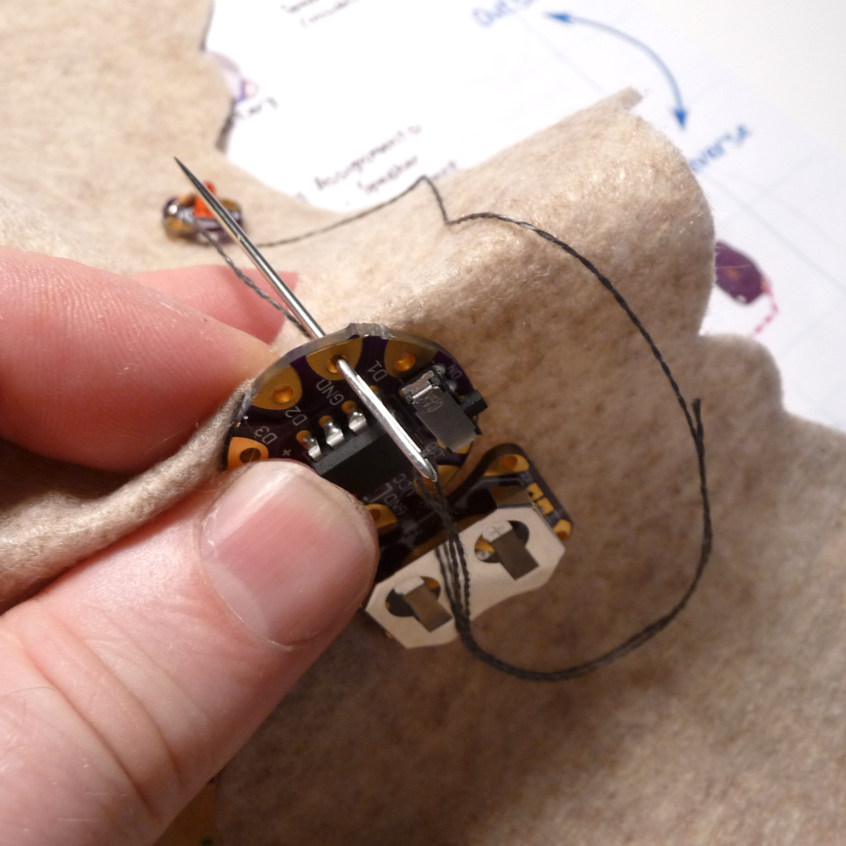
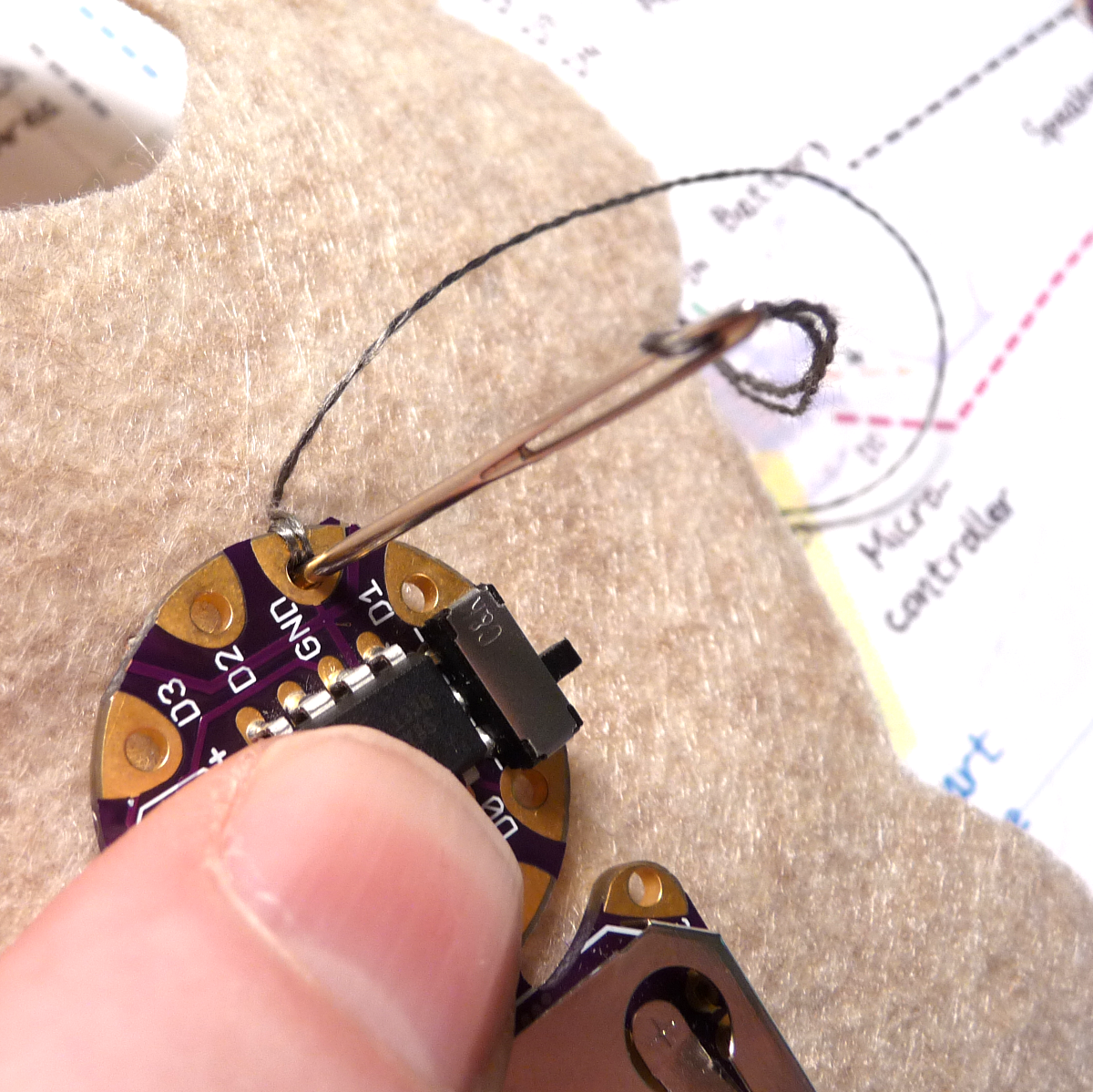
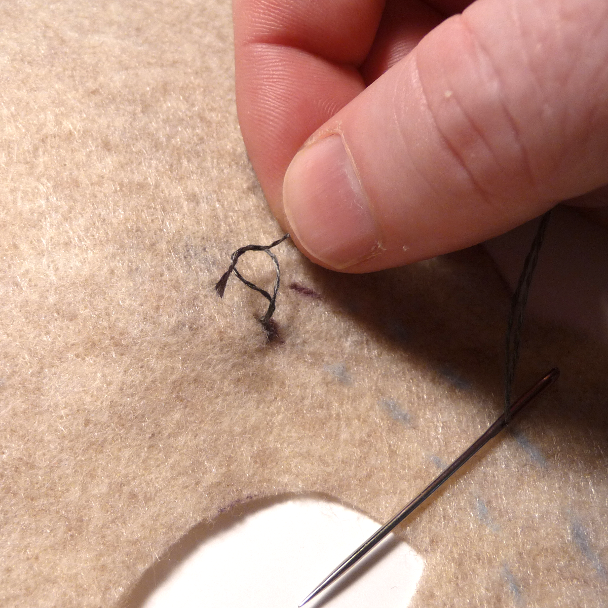
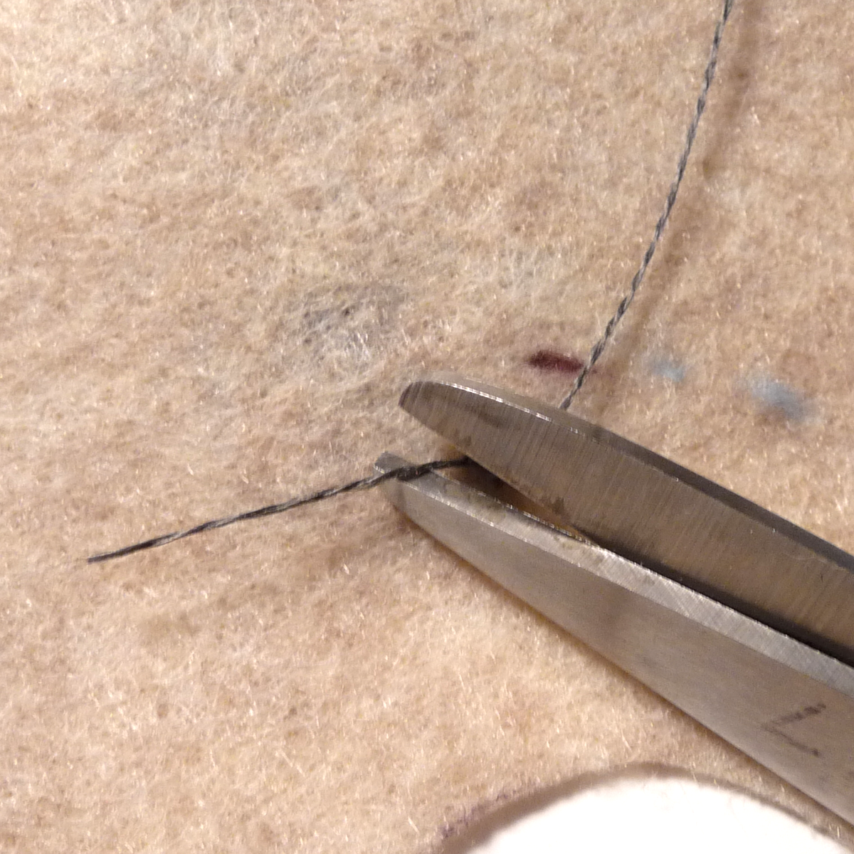
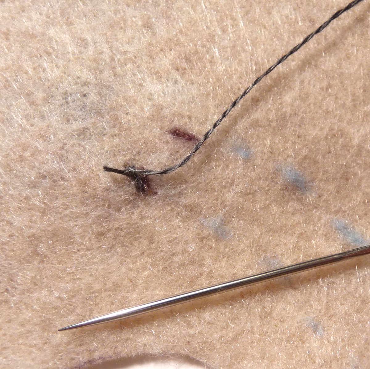
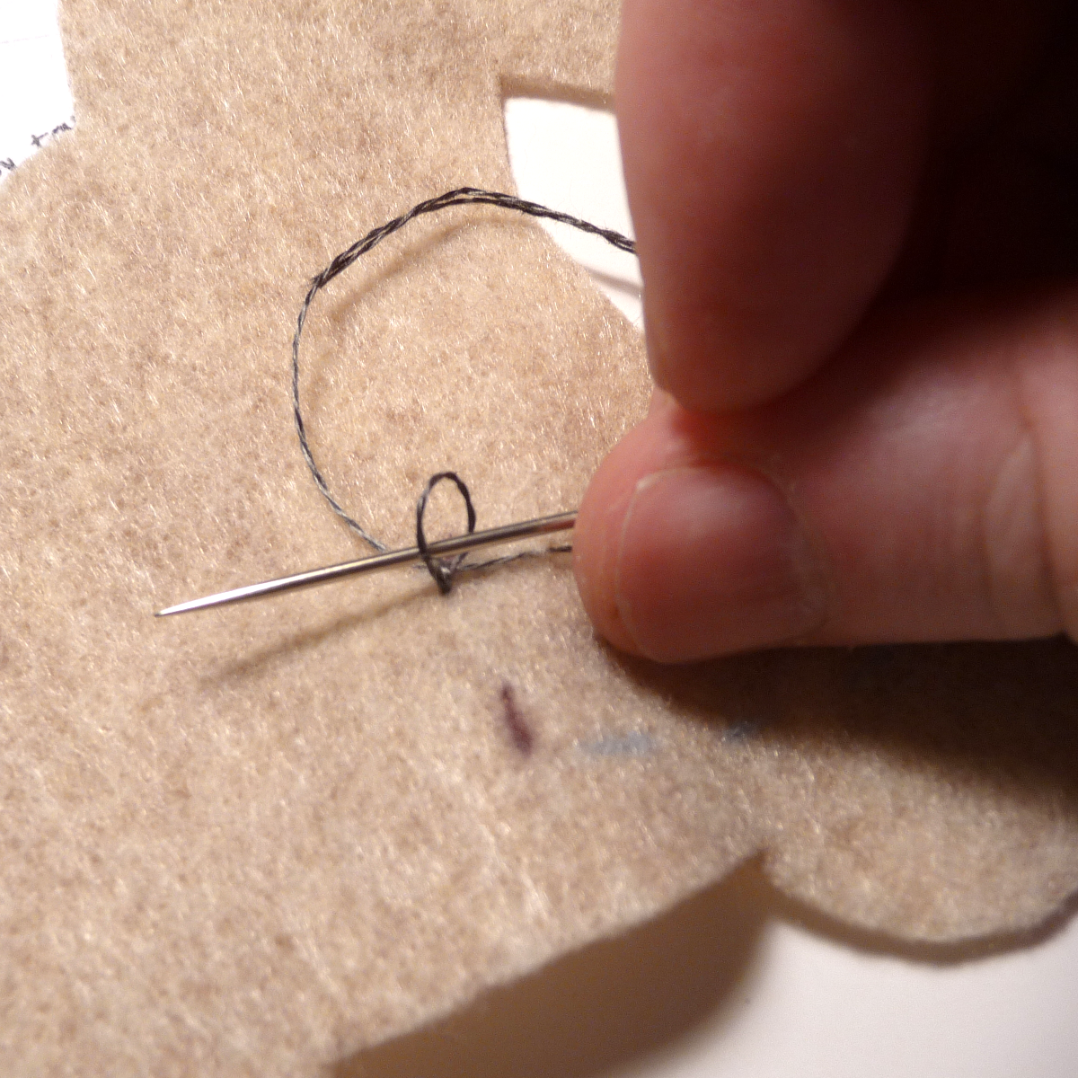
We will look at the first knot in detail. It is important to get a good electrical connection and avoid short circuits, so take your time and keep it neat.
- I like to start with the end of the thread on the inside (or bottom) of the project and have the upward stitches come up on the outside of the ground eyelet. Leave about an inch left underneath, enough to tie a knot later (picture 1).
- Make one loop around the eyelet without passing through the fabric. Since the inside of the hole is plated, this will help make a good electrical contact (picture 1).
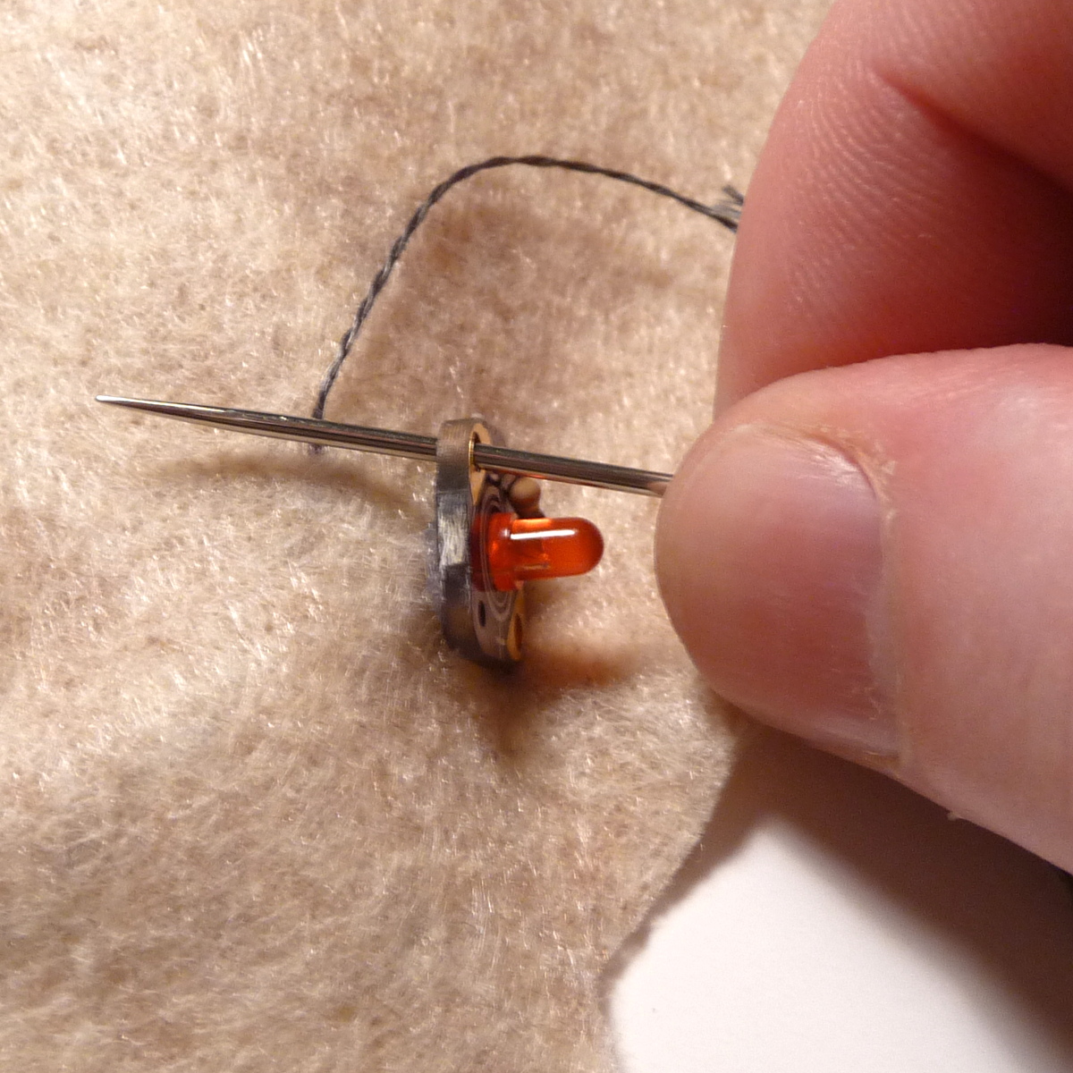
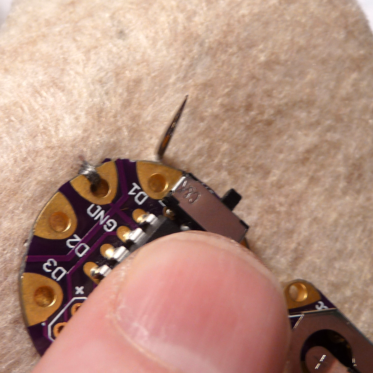
- Make several passes through the fabric and the eyelet to hold the board in place.
- Using the loose end, tie a knot on the inside of the project.
- Clip the end, leaving about 1/8 - 1/4 inch remaining.
First Stitch
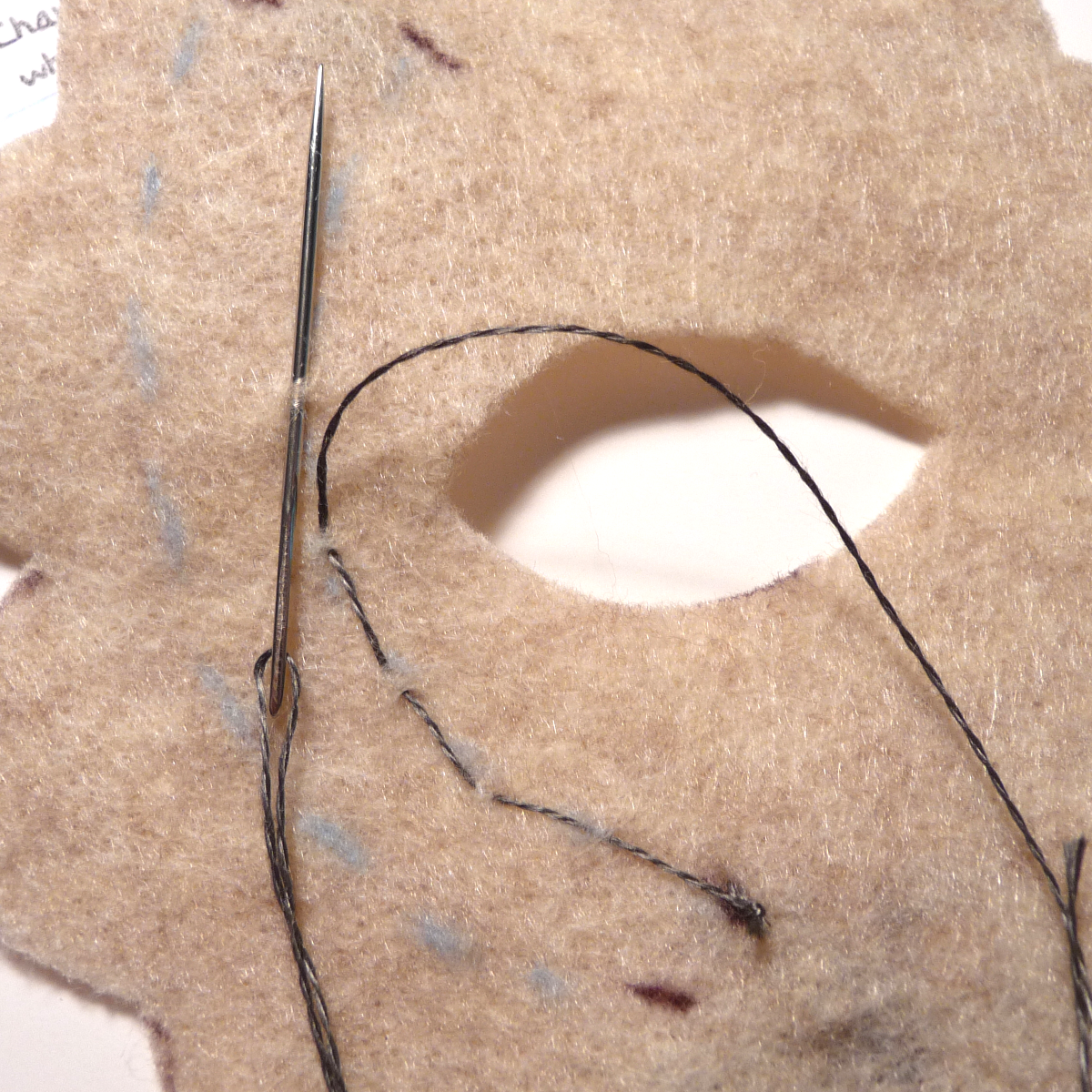
- Having made the first connection with the knot, it is time to run a stitch out to the LED ground. I like to keep the stitches on the inside surface, just nipping the material so the thread doesn't show through. You could, however, incorporate that into the design.
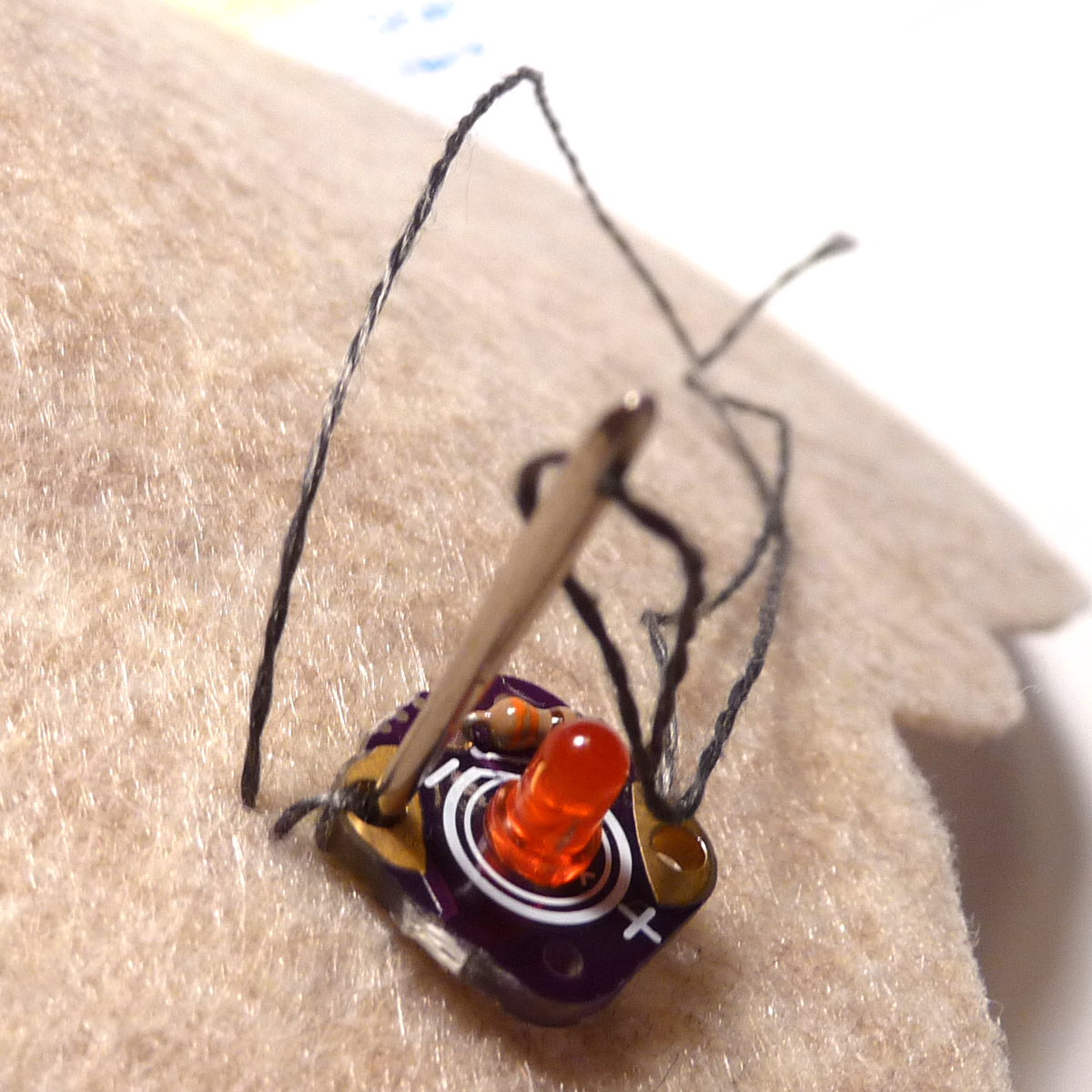
- Once you have reached the LED, make a loop through the eyelet only again to get the good connection.
- Make several loops through the eyelet and material to secure the piece to the fabric.
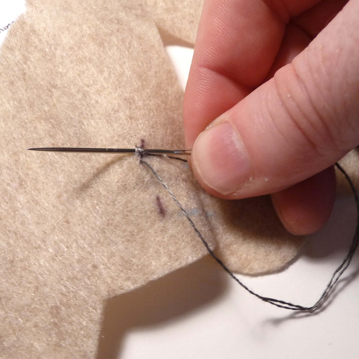
- End the stitch with a knot by passing through a loop and pulling it tight several times.
- Cut the line leaving 1/8 - 1/4 inch remaining.
See Me
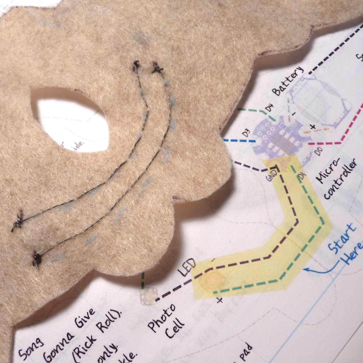
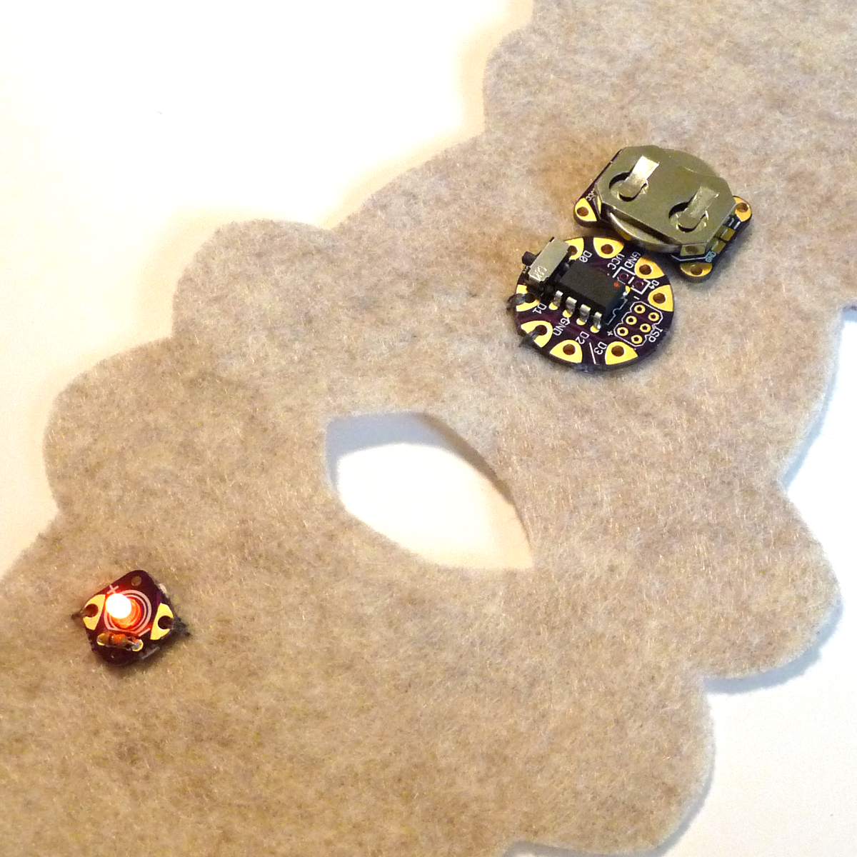
- Having done the first trace, all you need to do is repeat it with the signal line from D1 to the LED positive side.
- Once complete, place your battery in and test by touching pad D3 on the microcontroller and a ground. This should trigger the light to come on.
If you don't get the expected outcome, start by checking your lines are not shorted and that they are connected to the correct eyelets, and with the correct orientations.
Check to see if you have a fresh battery.
Use a multi-meter to locate any shorts.
Touch Me
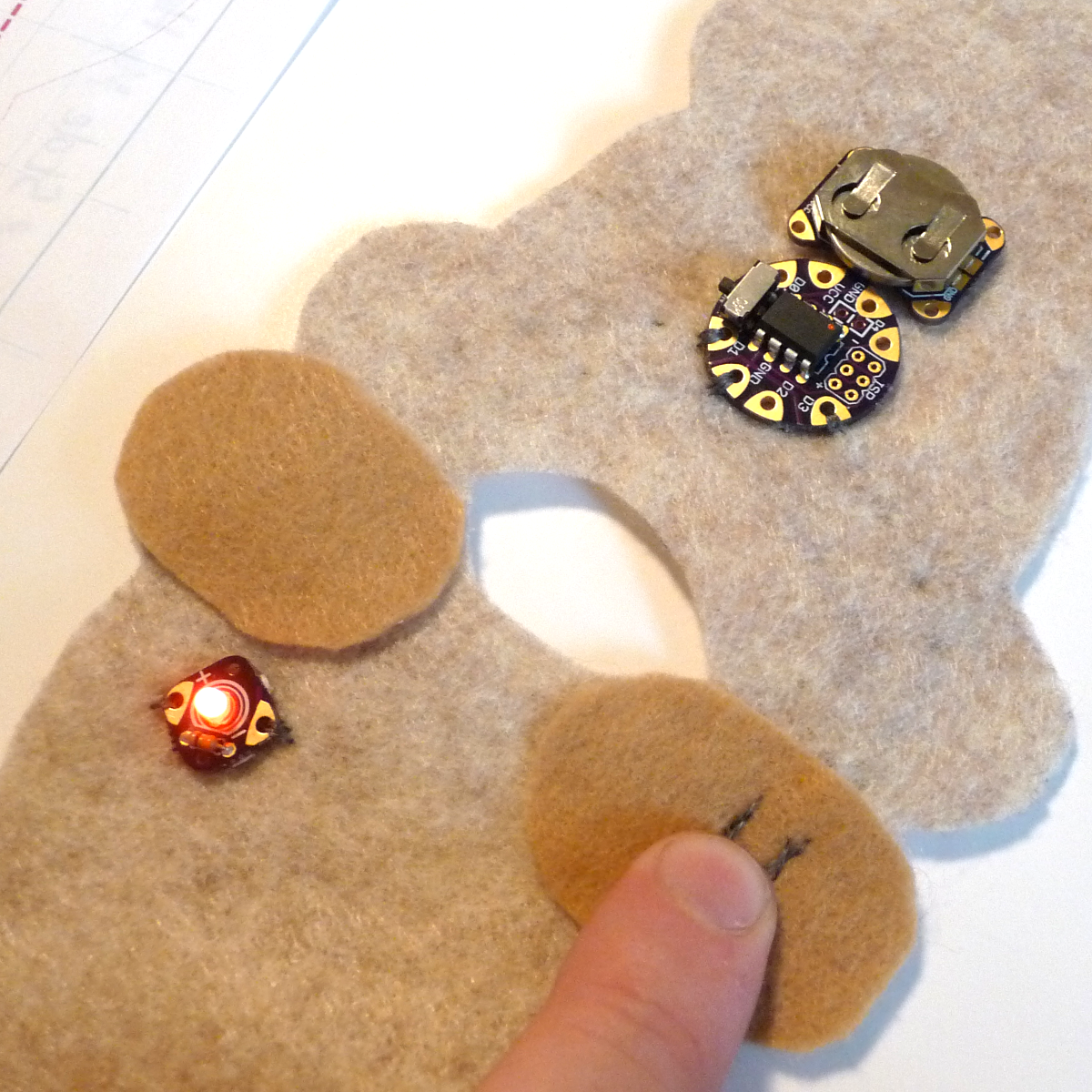
Once you have your first output tested (the LED), it is time to add an input.
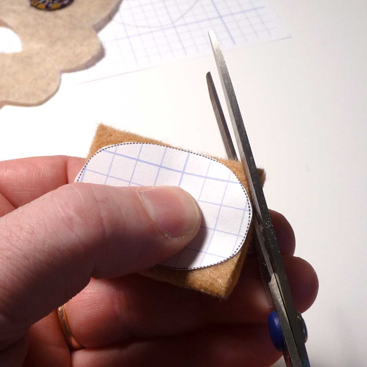
- Cut the feet from the template pattern.
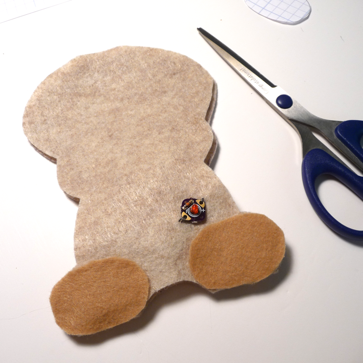
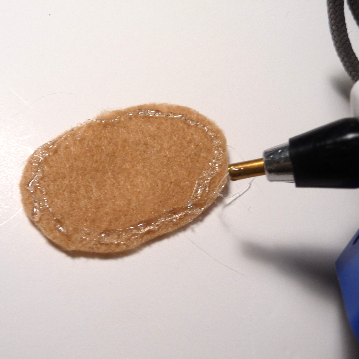
- Trace and cut the feet from the felt and hot glue or sew them to the body.
- Remember to be sparing with the hot glue as it is hard to sew through.
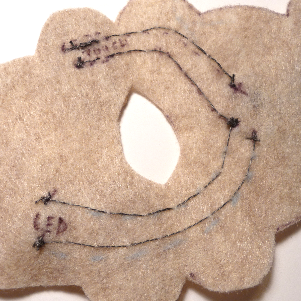
- Sew lines from ground and D3 to the paw area.
- Insert the battery and test again like before.
If you don't have the correct indication, trouble shoot as before with the LED.
If you are having shorts, but can't locate them, use the sticky side of a piece of tape on the felt to remove any stray conductive strands.
Ensure lines are 1/4 inch apart so that loose conductive strands can't short out on the other signal.
Hear Me
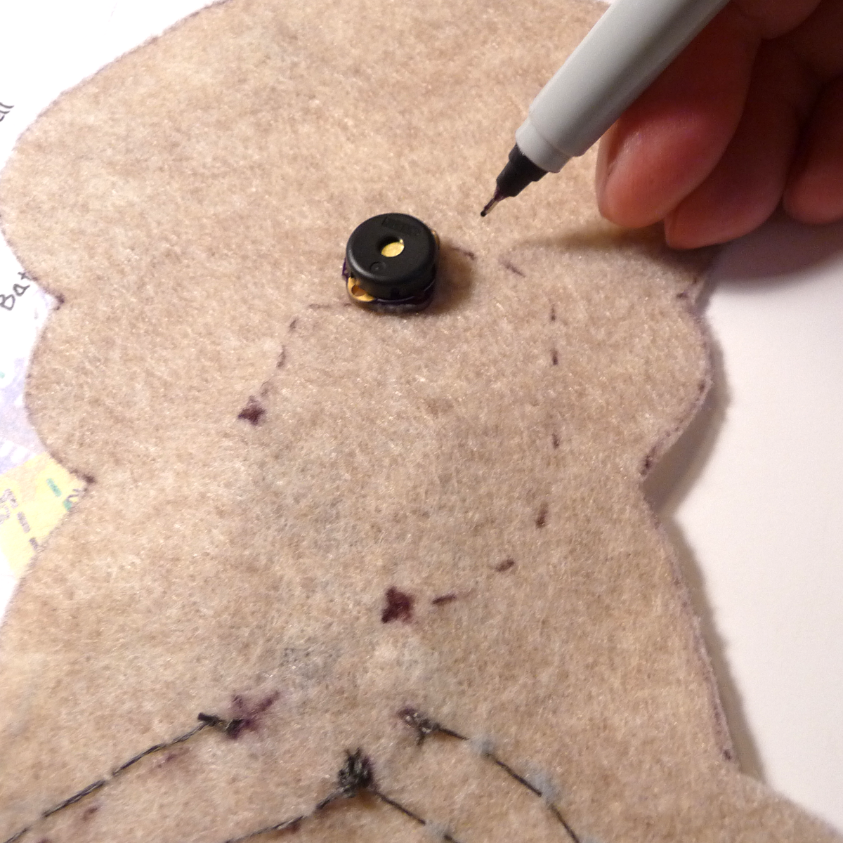
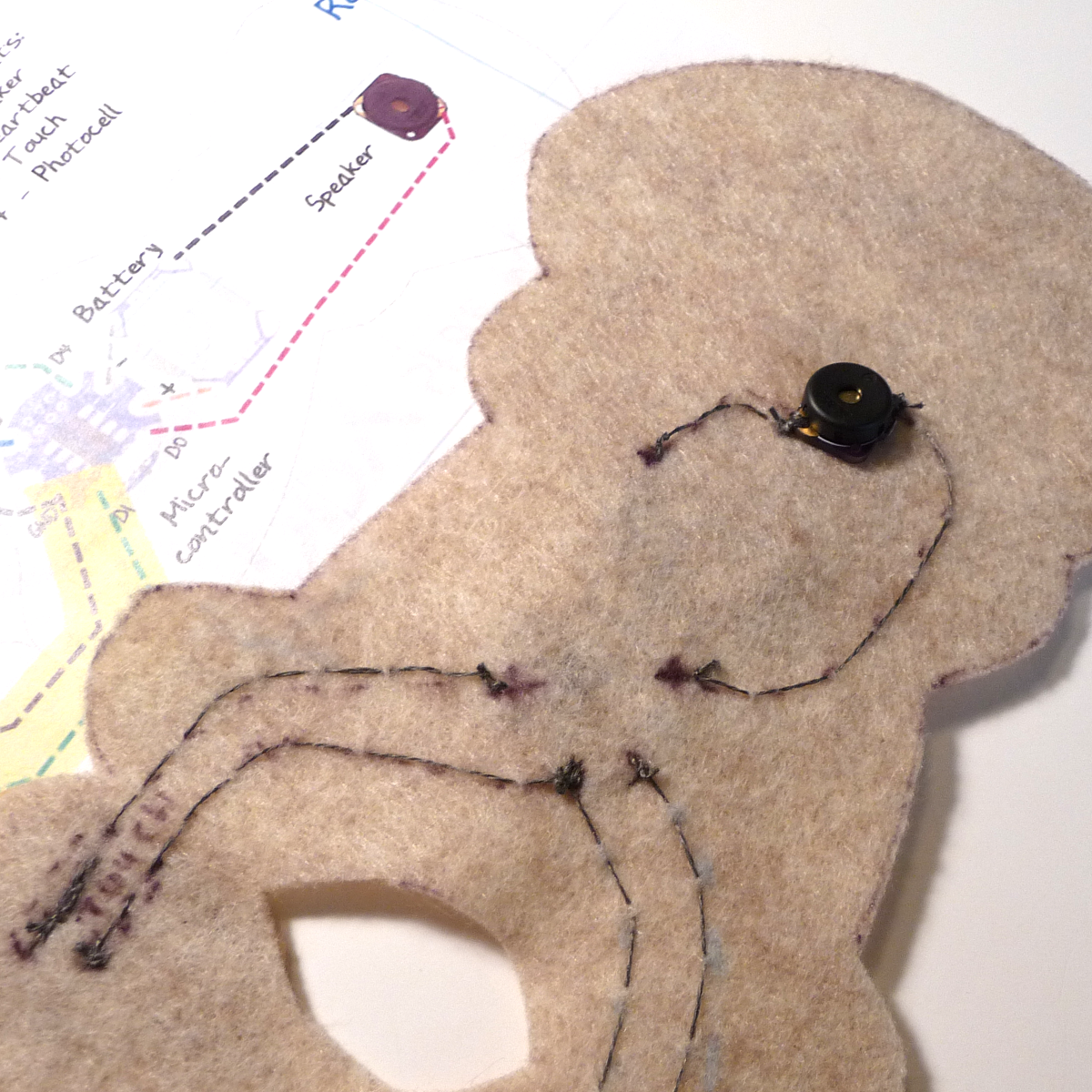
With one input and output installed and tested, you are a pro! Add the speaker as with the LED, using hot glue to tack it place on the inside surface of the project. Stitch ground and D0 to the speaker and test.
If you do not get sound, make sure the microcontroller is in the correct mode (two flashes on startup is silent!)
Check for shorts as before.
Let There Be Light
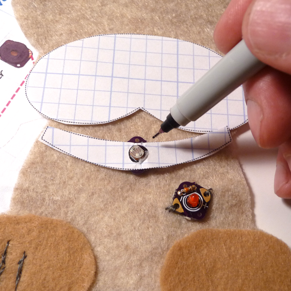
Our final component is a light sensor. It is optional, but will let you have fun with turning lights on and off.
This can be either a photoresistor, or a phototransistor. I like using a phototransistor because it is cheaper and faster, but it does require you pay attention to polarity.
Attach the photocell like you did the LED.
Final Touches
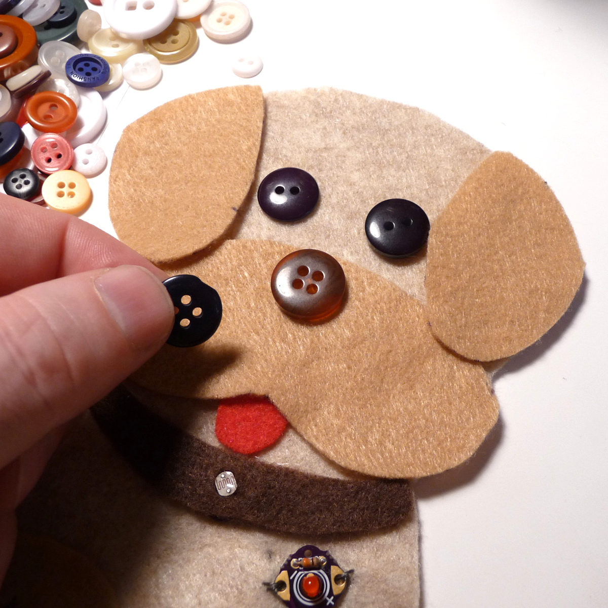
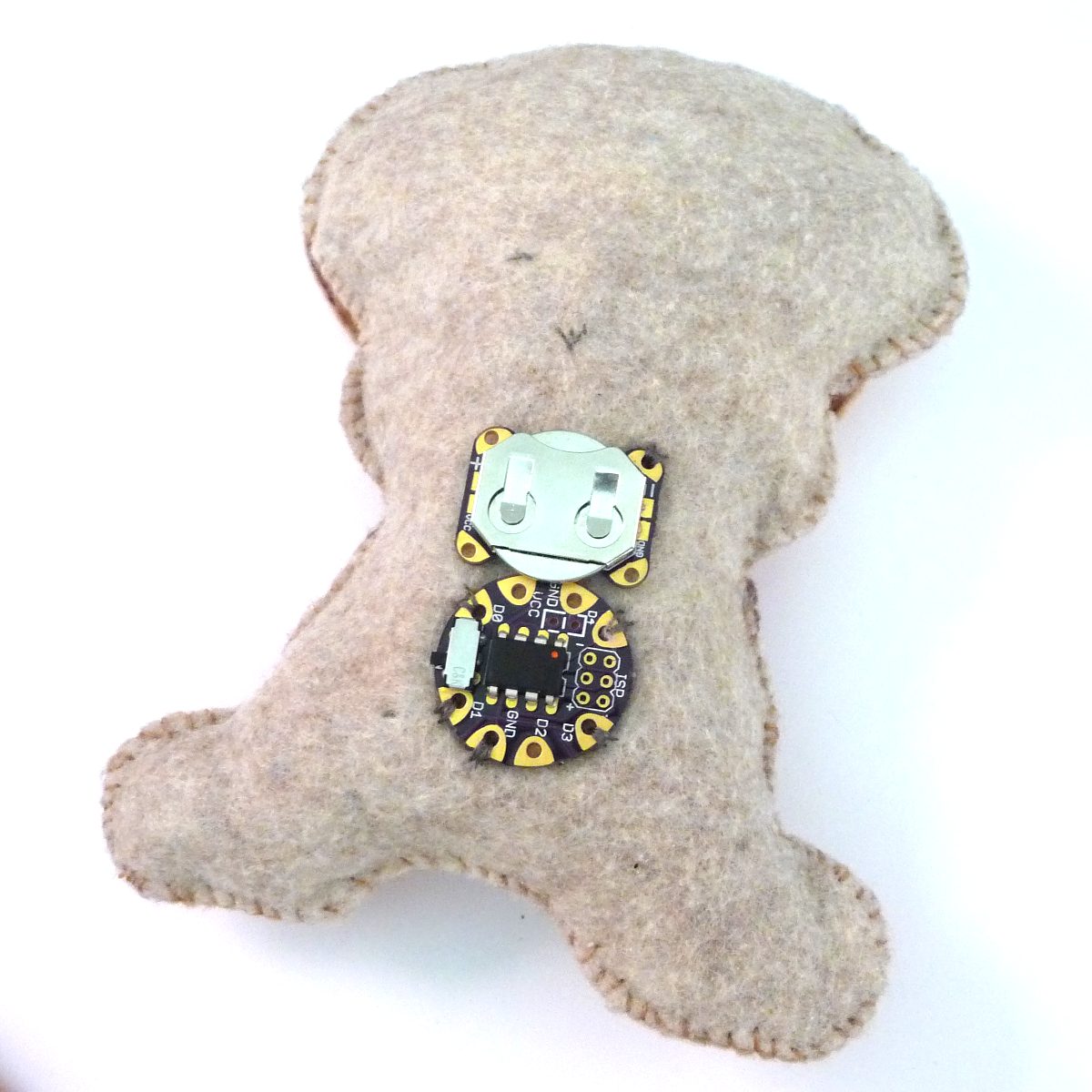
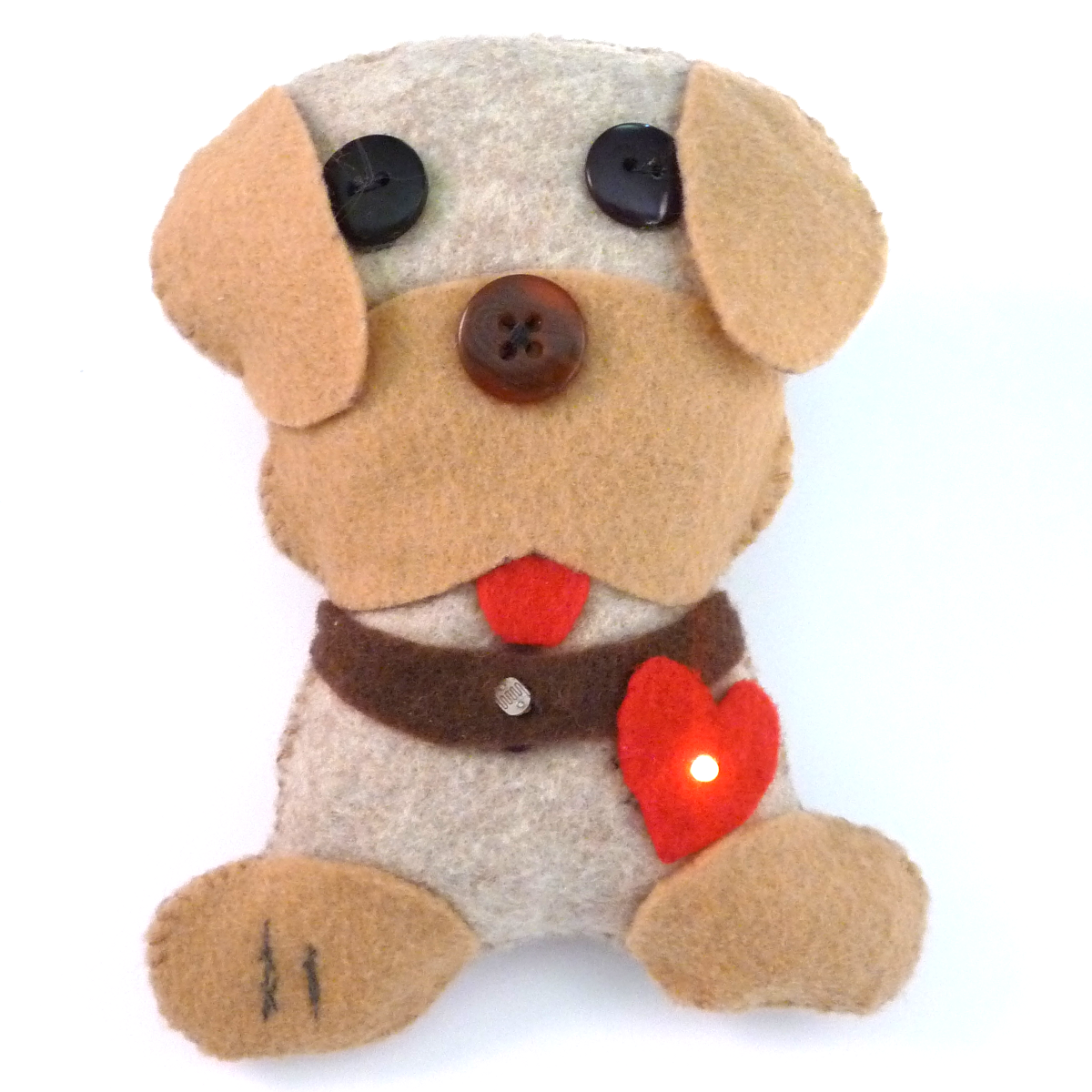
Home stretch. If everything checks out, you are ready to put on the final touches. Add any embellishments and then sew up the edges with regular thread or embroidery floss and stuff it with polyester filling or some other material.
Credits and Final Thoughts
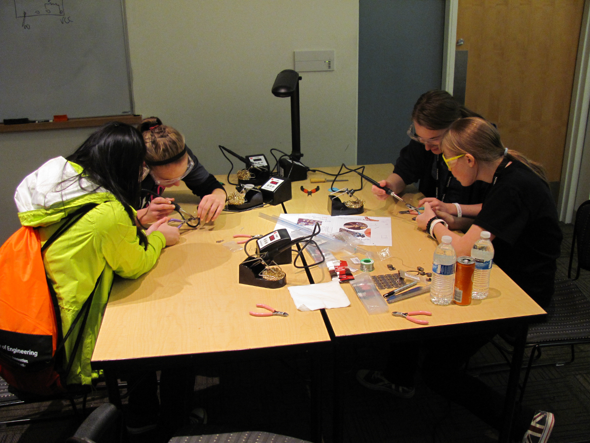
Hopefully you had a successful project. Post in the comments if you have suggestions or frustrations. Soft circuits is a relatively new Maker area and there are still a lot of rough edges still to be smoothed out. Hopefully you've realized this project helped quite a bit.
The original idea for this project started with MIT's Soft Circuit Facilitator's Guide and the Lily Twinkle Board. The "snap-a-part" idea is based on LilyPad's ProtoSnap concept. My goal was to make an inexpensive "through-hole" soft-ciruit board allowing multiple input/outputs that could be assembled and tested by the student before being implemented into a soft-circuit project.
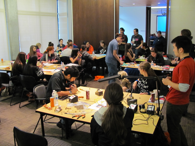
I am grateful for ChickTech.org for enabling me to develop this project. Their programs help young women discover career opportunities in engineering fields. This project started as a simple one-hour workshop for teenage girls and as evolved in to an excellent teaching resource that I am hoping to share with other!