Creating a Lamp in SelfCAD for 3D Printing
by Sammy50 in Workshop > 3D Printing
1314 Views, 13 Favorites, 0 Comments
Creating a Lamp in SelfCAD for 3D Printing
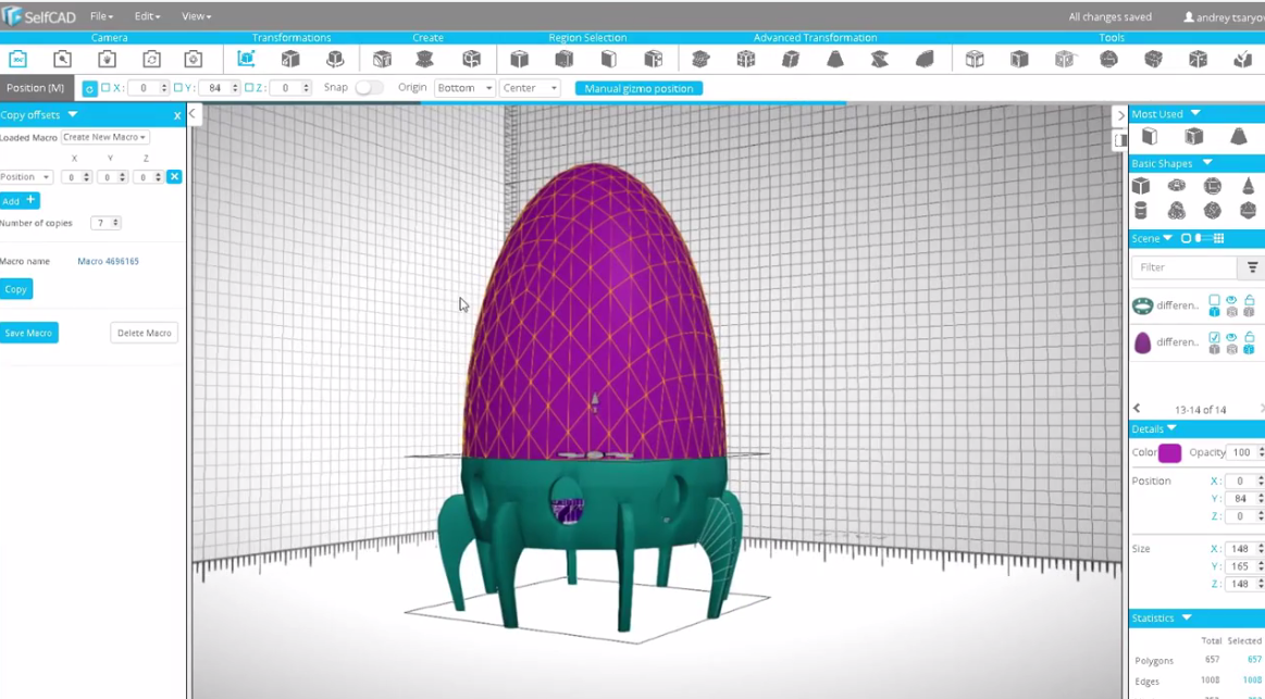
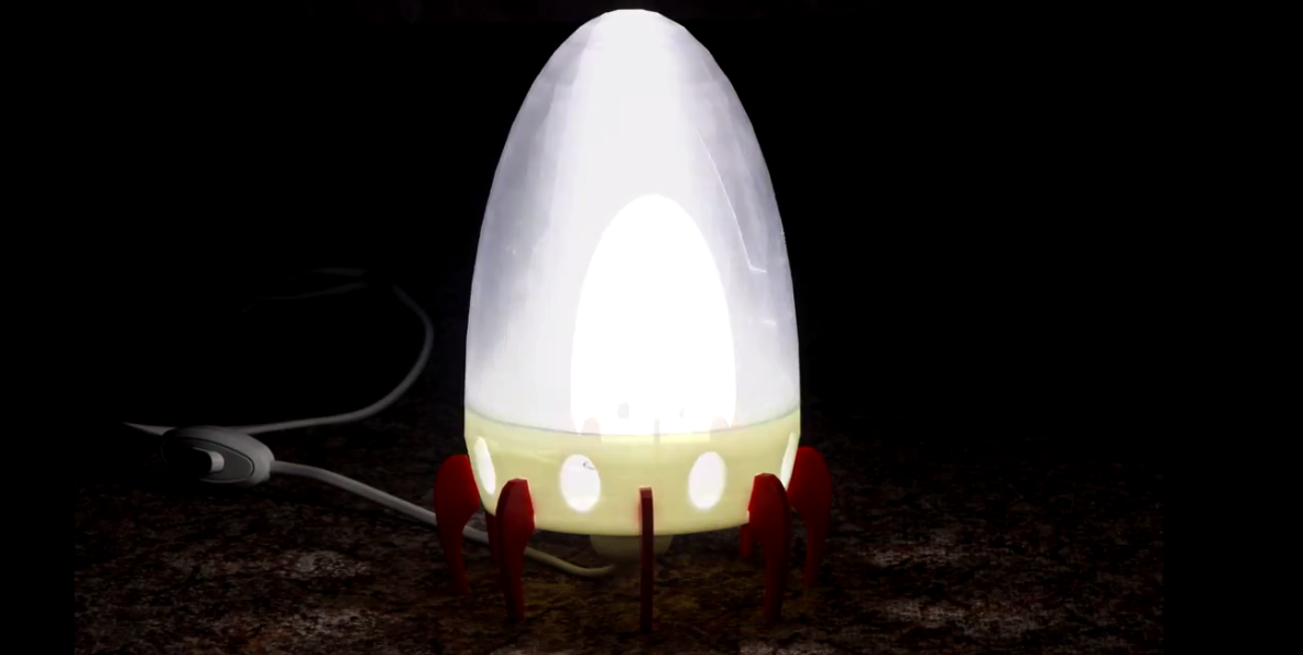
- In this instructable, I am going to show you how I created the above lamp for 3D printing using browser-based 3D software called SelfCAD. SelfCAD is a new 3D software which offers an easy to use platform that allows you to model, sculpt and print all under one program. Visit www.selfcad.com to claim your 30 day free trial and later buy a one-year subscription for only $39.99 or pay $4.99/m, but if you are a student or teacher SelfCAD is free. Claim your free subscription here: SelfCAD for Students.
- If you have created an account let's get started!
Start Modeling
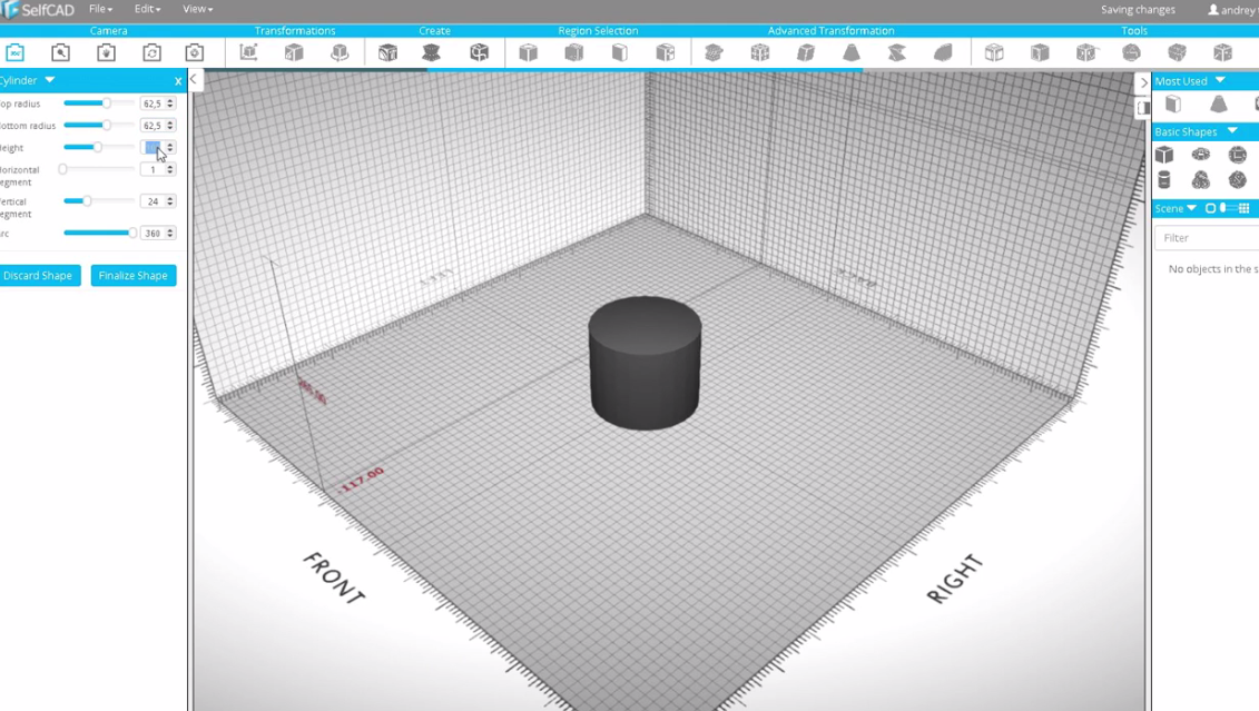
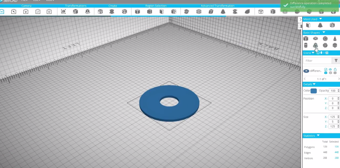
- To begin, click on the Cylinder, found in the Basic Shapes. Set the Top and Bottom radius to 62.5, Height to 5 and set the Vertical Segment to Maximum and click Finalize.
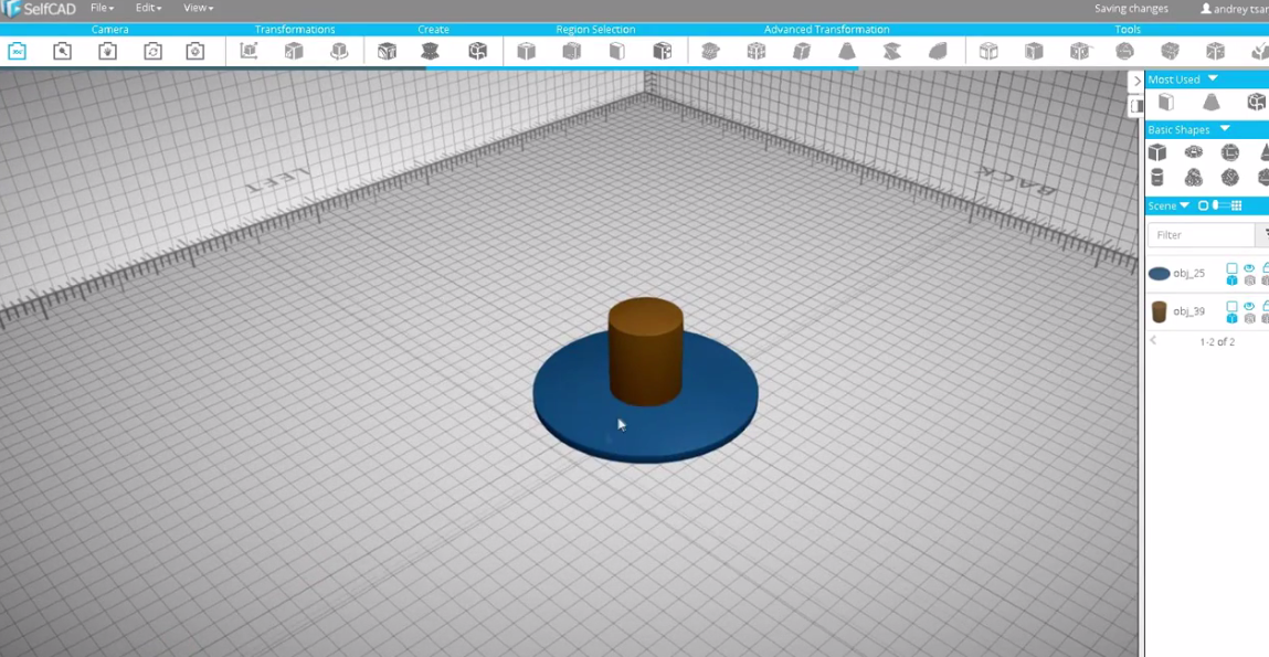
- Create another cylinder with the Top and Bottom radius 20 and height 50.
- Exclude this cylinder from the first one using Boolean Difference. You can do this by select Boolean in the Tools menu and select Difference and then Apply.
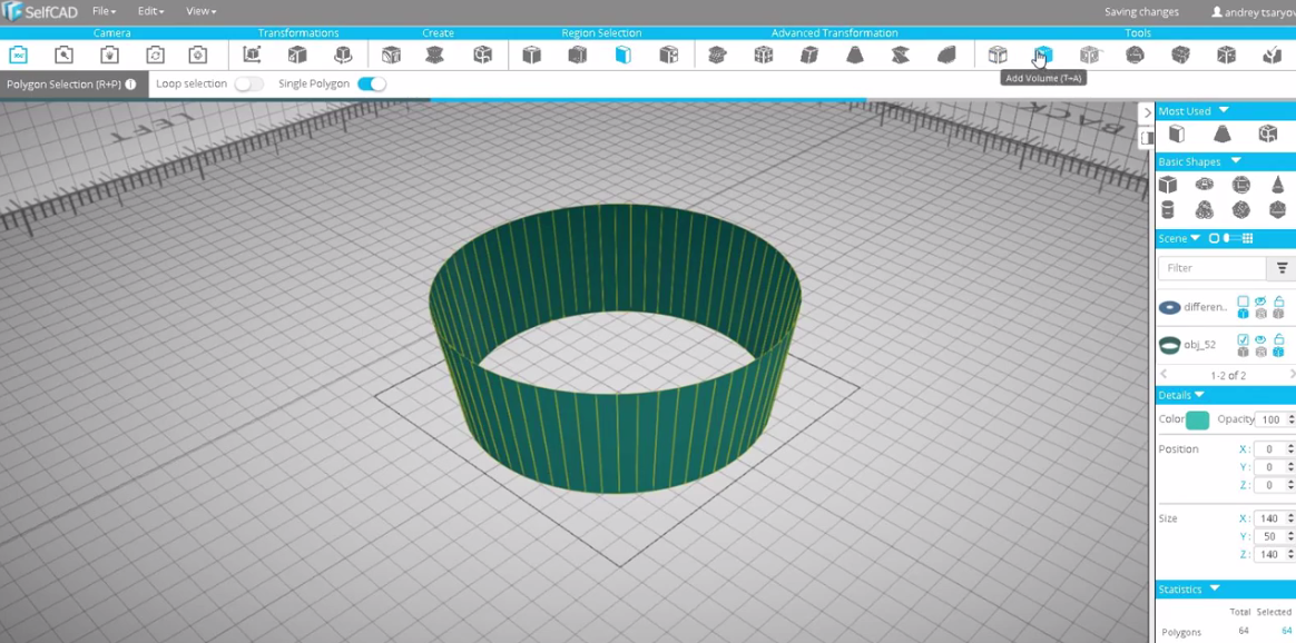
- Create another cylinder which will form the walls of the bottom of our lamp. Set the Top and Bottom Radiuses to 70 and 62.5 respectively and height also 50.
- Using the Polygon selection, select the top and bottom parts and delete them and click Add Volume and then Apply.
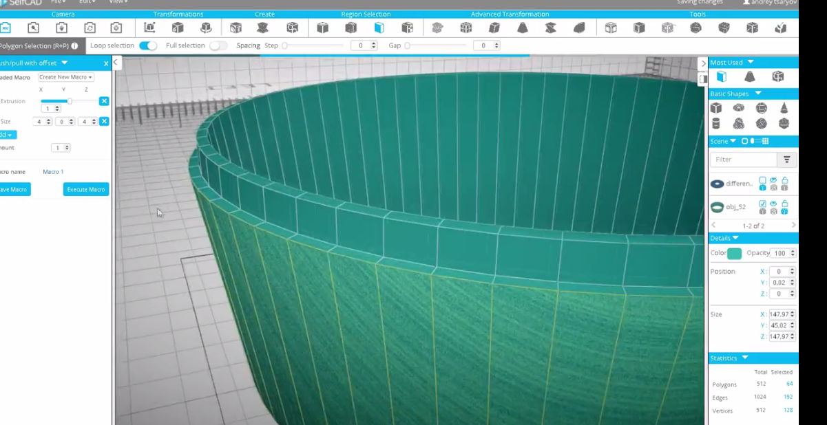
- In the Edit Segment, select Push/pull with offsets. Then select all the outside polygons using polygon selection tool with loop selection turned ON.
- In the push/pull with offsets menu click Add then Extrusion. This allows you to generate macros by allowing you to change the settings provided. Set the Extrusion to 1 , and set Y value to -2 in Size tab and -2.5 in the position section then click Execute Macros, remove the posttion and set the values of x, y and z to 4, 0 and 4 respectively then click Execute Macros. You will be able to obtain shape related to 5th above.
- Click Resolution and set it to 4 then click Rebuild.
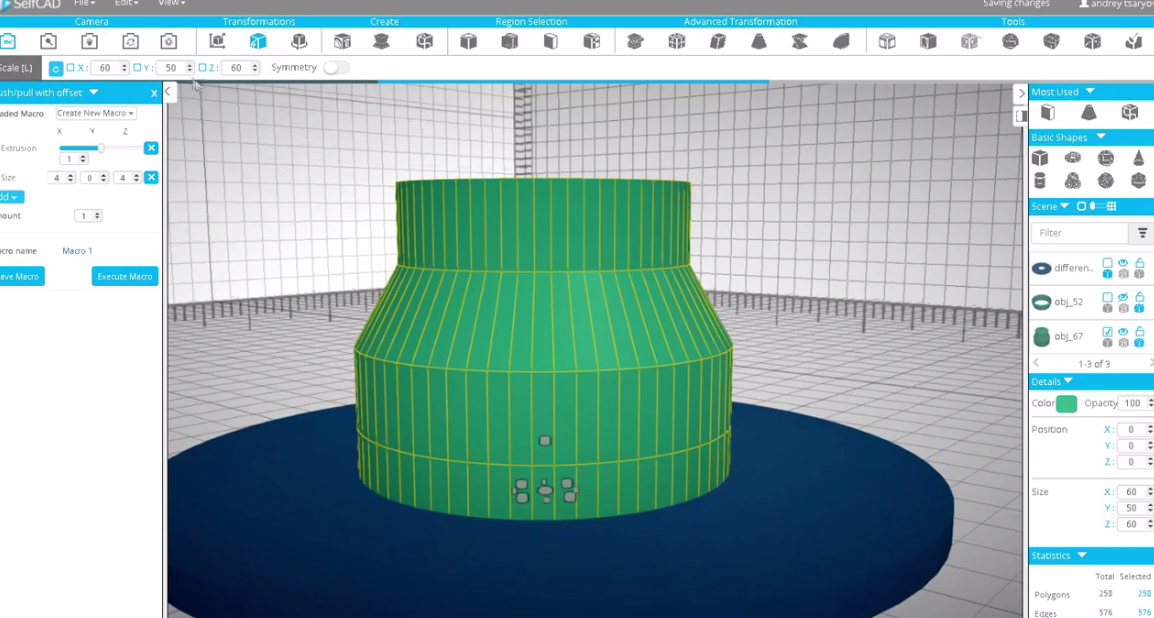
- Shape the model using the polygon selection and Scale tools.
- Hide the Shape and add another Cylinder. Set the top and bottom radius to 30, height 50 and horizontal segment to 4.
- Using the Loop Polygon Selection, select the top polygon and select Scale,make X and Z 46.
- Select the entire cylinder and scale it by 12.5 Y coordinate. Check the video to see how it's done.
Creating an Attachment
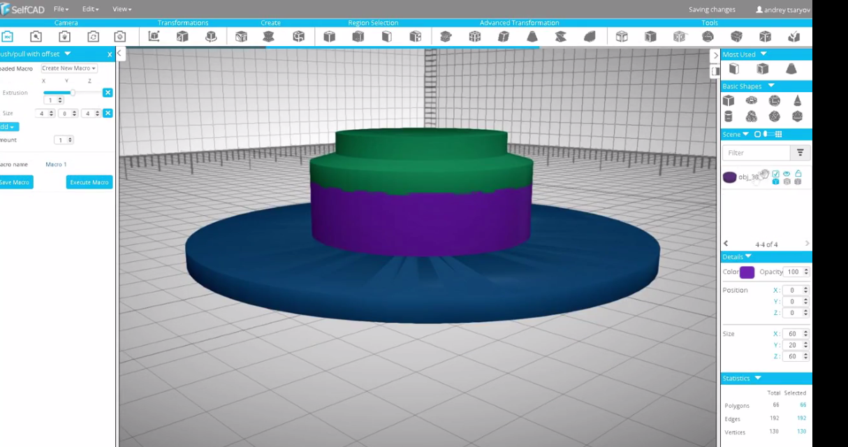
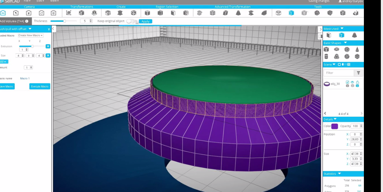
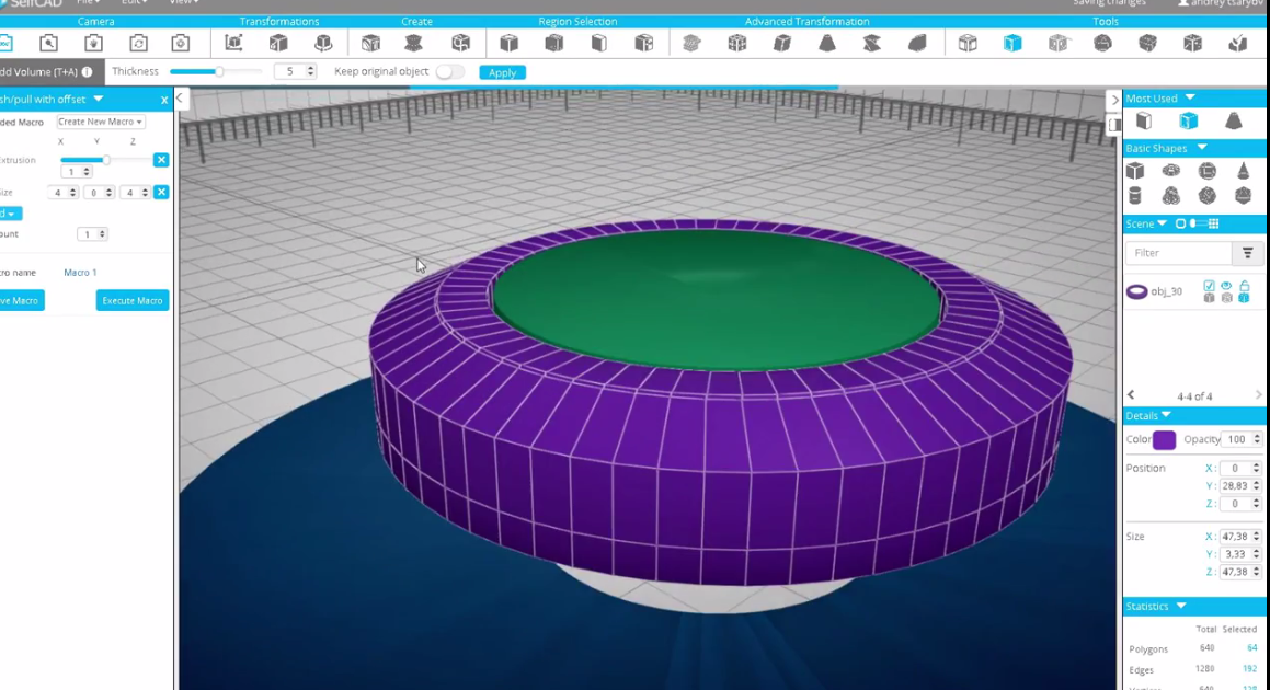
- Create another cylinder and set the top and bottom radius to 30, height 20 and vertical segment 64 and click apply.
- Scale it and remove the top and bottom services. Set the Resolution 5, and using Polygon selection, move and scale, while having the Wire Frame on create the walls of the attachment.
- Then using the Add volume tool, create the attachment.
Creating a Cube to Be Used for Cutting Half of the Attachment
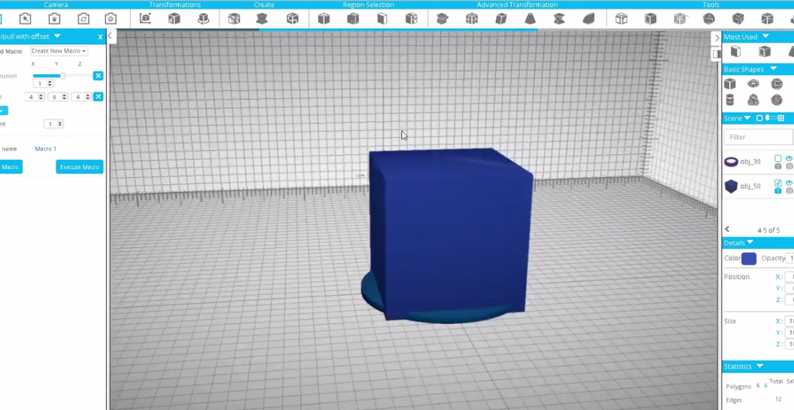
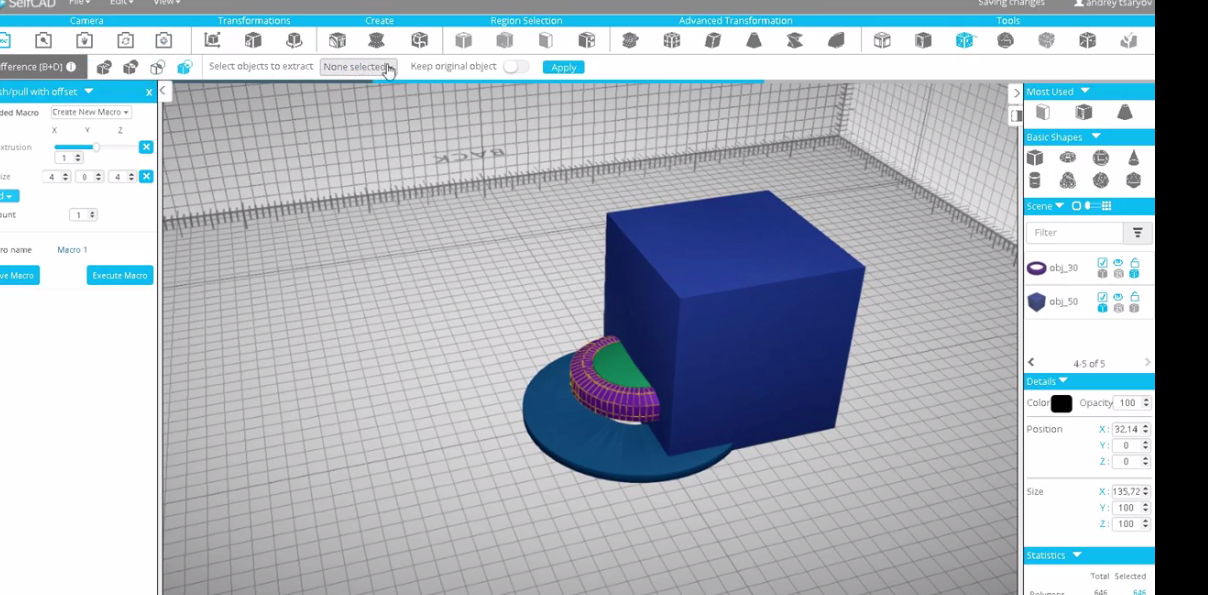
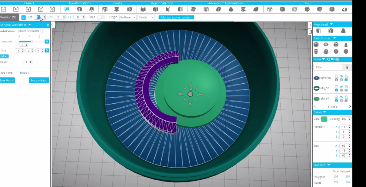
- Select a cube from the Basic Shapes segment. Click Move Tool and in the Origin Section set Left.
- Click Boolean then difference and then click Apply.
- Position the models to make them fit each other.
Creating Openings on the Walls
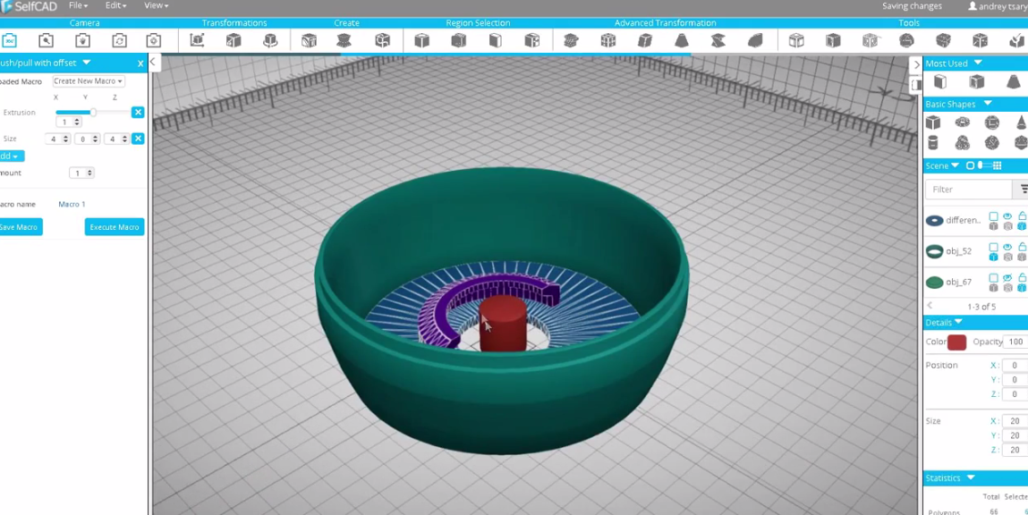
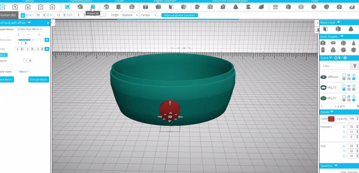
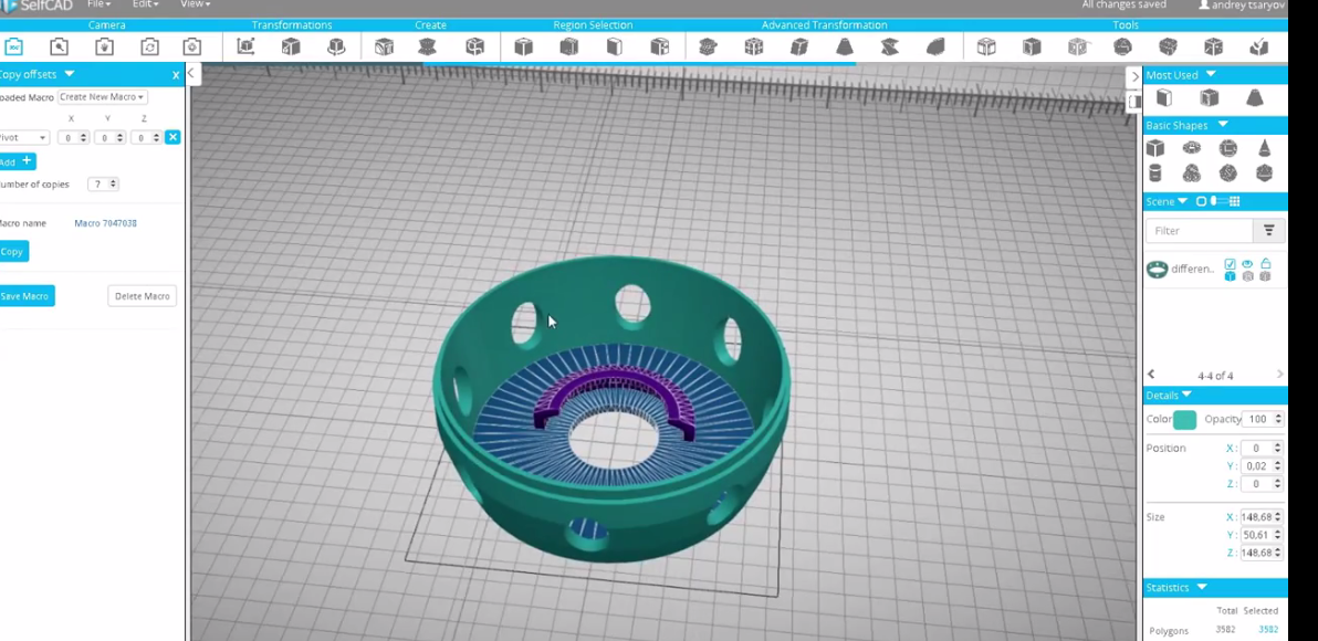
- Select cylinder and set the top and bottoom radius to 10, height 20 and maximum vertical segments.
- Rotate the cylinder to face the side of the model as shown in the second image above.
- Position and scale the cylinder and open the Copy Offsets from the Edit menu. Copy Offset is similar to push tool with Offset.
- Select Pivot in the position tab. Set the number of copies to 7 then click Copy.
- Select all the created Shapes and the base. And using the Boolean Difference, Exclude the Cylinder.
- The holes will be created as shown in the image 3.
Creating Legs
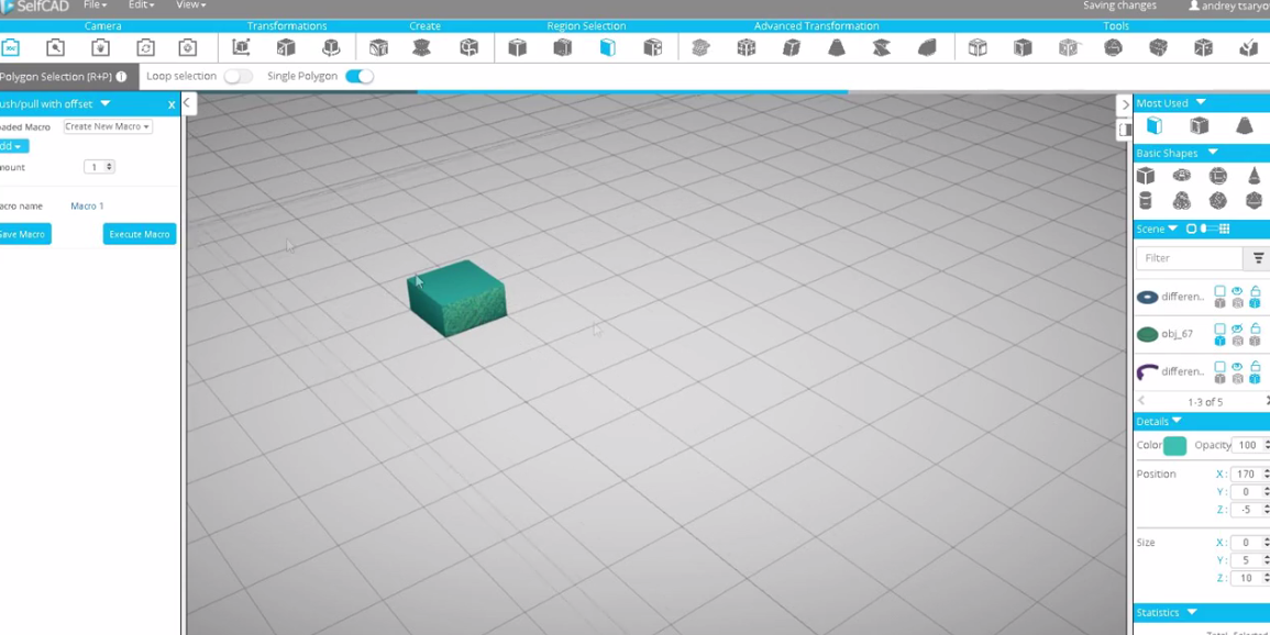
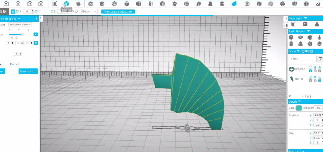
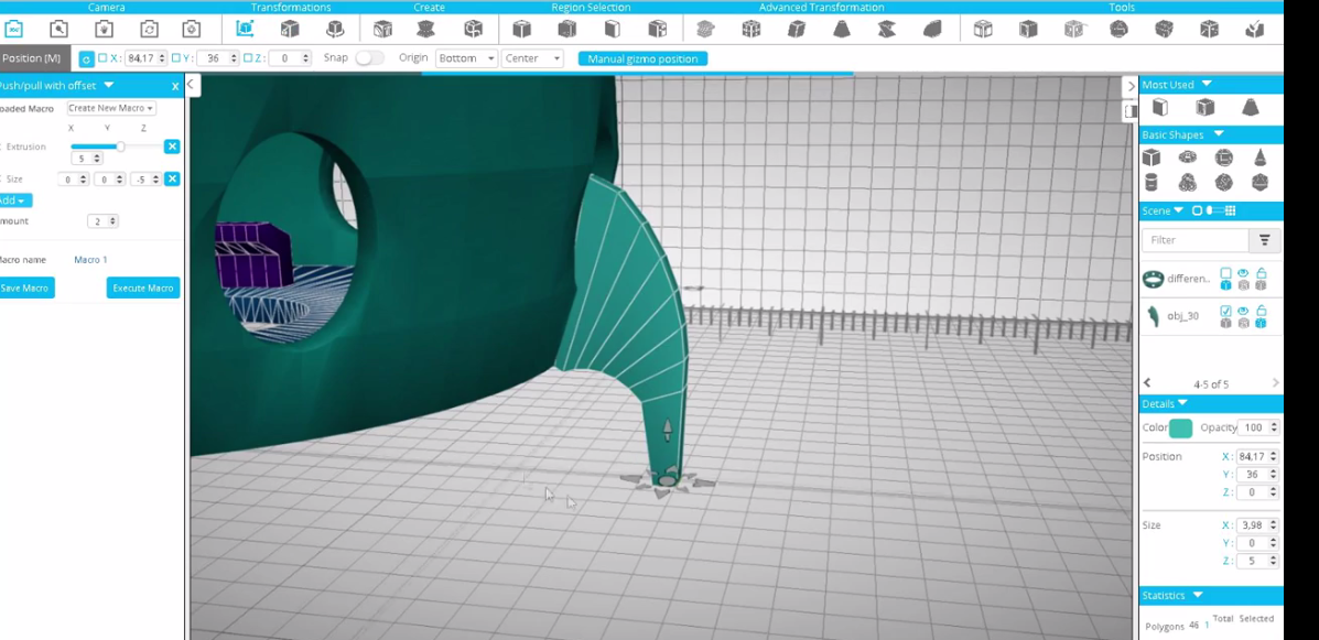
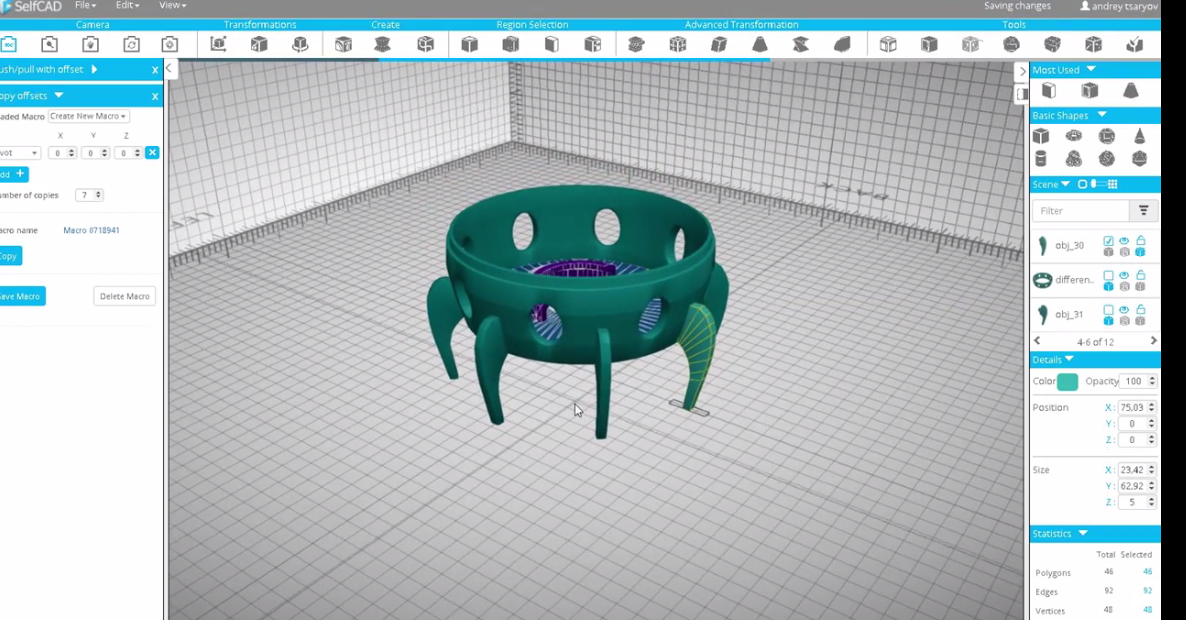
- Select the Cube and set the width, height and depth to 10, 10 and 5 respectively.
- Rotate it and go to the push/pull with Offsets. Select one side and in Macros, add Extrusion and size.
- Set Extrusion to 1, Size 32 then click Extrude Macros.
- Then set Amount to 5, Extrusin 5 and Z axis in the size to -5.
- Using Move tool, you can move the selected Polygon.
- Rotate the Shape, and using the Tools Bend, Scale, Polygon Selection rotate and move to be as shown in the 2nd image above, then move it towards the model, check the video to see how to fit the leg in the model.
- After fitting the model, Click Copy Offsets in the Edit Menu, select Pivot in the Position tab and set Number of copies to 7 then click Copy.
- Select all the legs and click Boolean, then Difference and select all the obj except difference in order to exclude the legs from the base.
- Hide the base and move the part that was removed and move it towards the legs.
Finalizing the Model
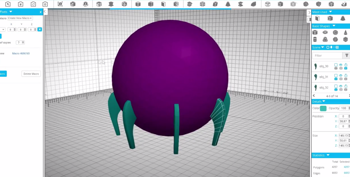
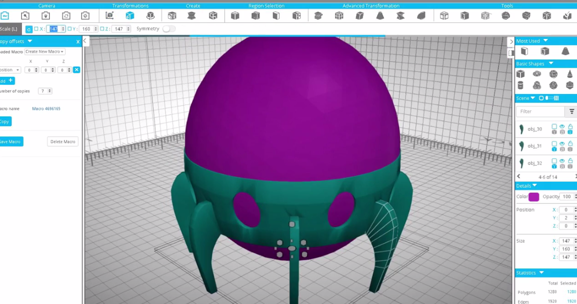
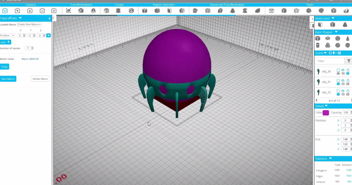
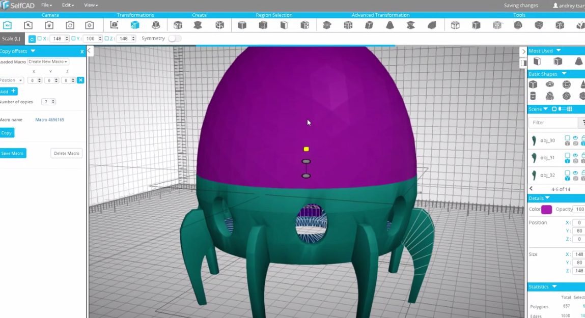
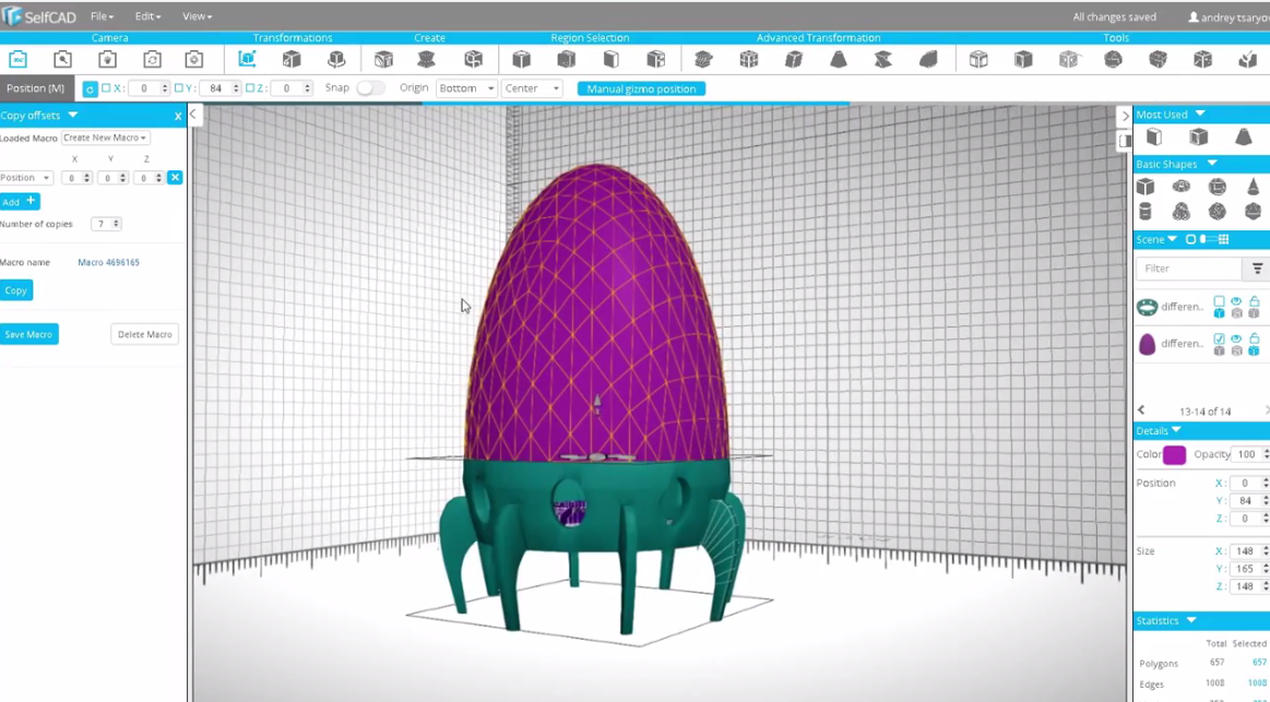
- Take a sphere and set the Radius to 80 and Segments to 3 then Finalize the shape.
- Using the Scale tool, Scale the sphere until the base is visible. Then adjust the Sphere according to the base of the layer.
- Create a cube and set the width, height, and depth to 80.Using Boolean Difference, extract the cube from the model to be as shown in the 4th image above.
- Move and scale it.
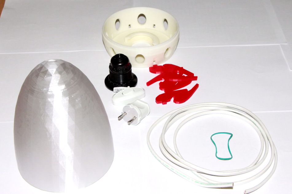
- Our model is now ready. You can download it as an STL file or print it directly in SelfCAD.