Creating a Customizable Case for Raspberry Pi and Arduino Boards in TkinterCAD
by Eco_Shef in Workshop > 3D Printing
2751 Views, 2 Favorites, 0 Comments
Creating a Customizable Case for Raspberry Pi and Arduino Boards in TkinterCAD
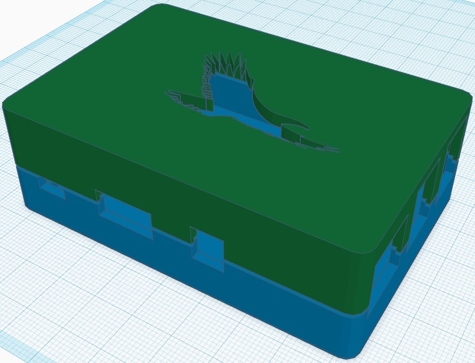
In this tutorial you will learn how to easily create a customizable case for any type of Raspberry Pi or Arduino boards and TkinterCAD basics. All you need is technical data for the preferred board in the DXF, STL or SVG format.
Introduction to the TkinterCAD
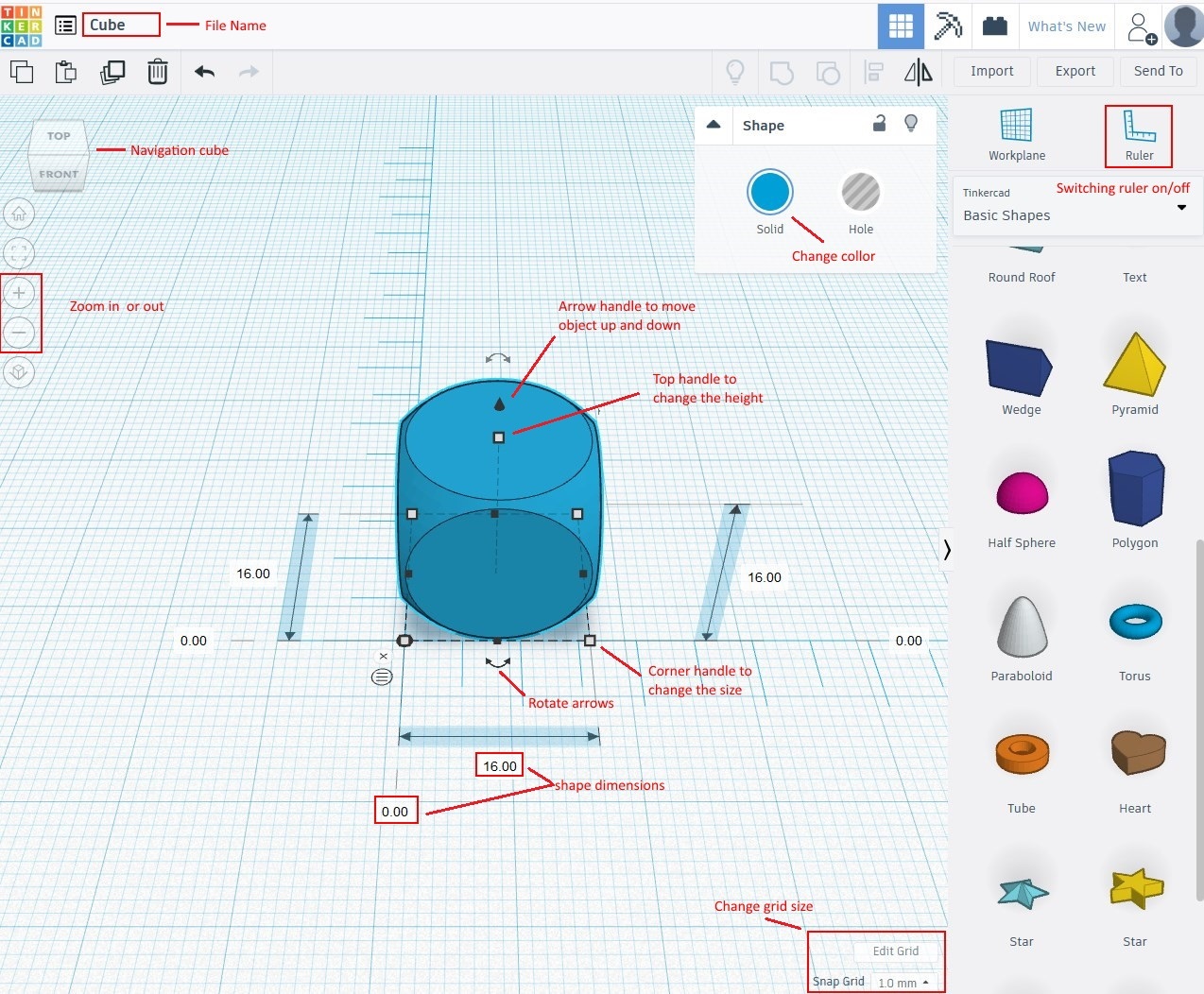
To move around TinkerCAD you can use the navigation tools in the top left corner – you can click each face with the left mouse button (LB) to activate it and by clicking on the corners of the cube you will access standard orthographic and isometric views, or you can hold LB and move the mouse to navigate in 3D space.
The same result can be achieved with keyboard buttons - the four arrows will spin your model left or right and tilt it up or down. You can also use the plus and minus to zoom in and out.
To select multiple objects you can hold down Shift while clicking on all the elements you want.
It will even be more efficient if you use the scroll wheel mouse:
● Right Mouse Button - Press and hold the right button (RB) and move the mouse, you will spin around in the workspace. This is known as the pivot.
● Middle Mouse Button - Press the middle button (MB) to move the model left or right. This is known as a pan.
● Left Mouse Button - Click the left button (LB) to select an object while you click, you can drag it too.
To select multiple objects you can hold down Shift while clicking on all the elements you want.
By using shortcuts you can significantly improve your design workflow (see Image).
Basic Operation in TkinterCAD Workspace
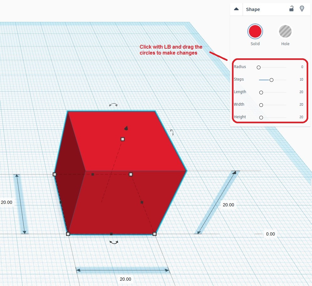
You can select any object with LB and by using object handles it can be scaled, moved or rotated. As a result you can perform most object operations with the mouse, and by adjusting the greed unit size you can easily change the object seize and position with the mouse dragging operations, without having to type in the size field.
The same operations can be performed in the object properties field.
NOTE: Selected points will change their color from white (unselected) to red (selected). Almost all operation in TkinterCAD can be done with mouse.
By using shortcuts you can significantly improve your design workflow.
To scale the shape uniformly in all directions, hold the Shift key while dragging
A TinkerCAD uses the positive and negative space concept. For example, you can create a box, which represents a solid, positive shape, and you can also place holes or openings as a negative shape. The holes will remove any solid material within their shape. By using the negative space we will hollow our case and create ventilation openings in our case.
Importing SVG Graphic Into TkinterCAD
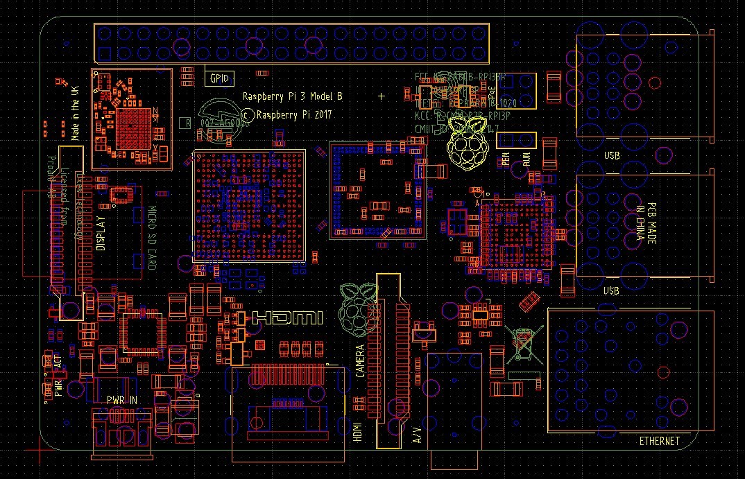
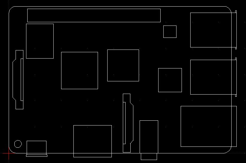
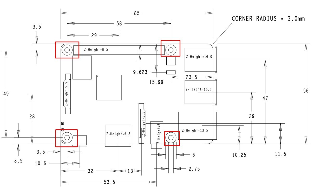
After opening DXF file in LibreCAD we will get quiet detailed drawing of the Raspberry Pi board. First of all we will have to remove all electronics parts from the board leaving only the connectors and the board outer contour.
After removing all unnecessary parts we can export our drawing in SVG file format, and then import it in TkinterCAD.
Now we can start to work with our shape
Import
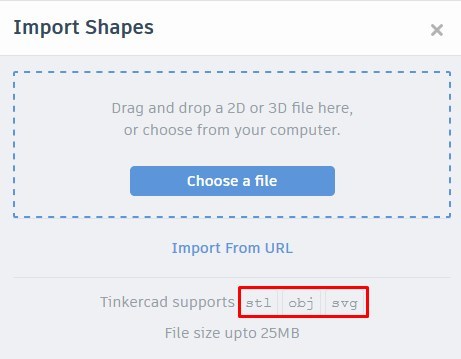
You can usually find the board size at the manufacturer web site, and it is often in DXF format, but TkinterCAD only supports OBJ, STL and SVG formats for importing.
To convert your DWG or DXF format into SVG you can use some CAD programs
like FreeCAD, LibreCAD etc. or you can use some online platforms like Convertio (https://convertio.co/de/dxf-svg/) or FreeFileConvert (https://www.freefileconvert.com/dxf-svg). In this example I did used LibreCAD.
Use the import menu to insert components and files (OBJ, STL and SVG).
Choose your .svg file located in your hard drive, and after that you can choose some options in the TkinterCAD import interface.
Base Plate
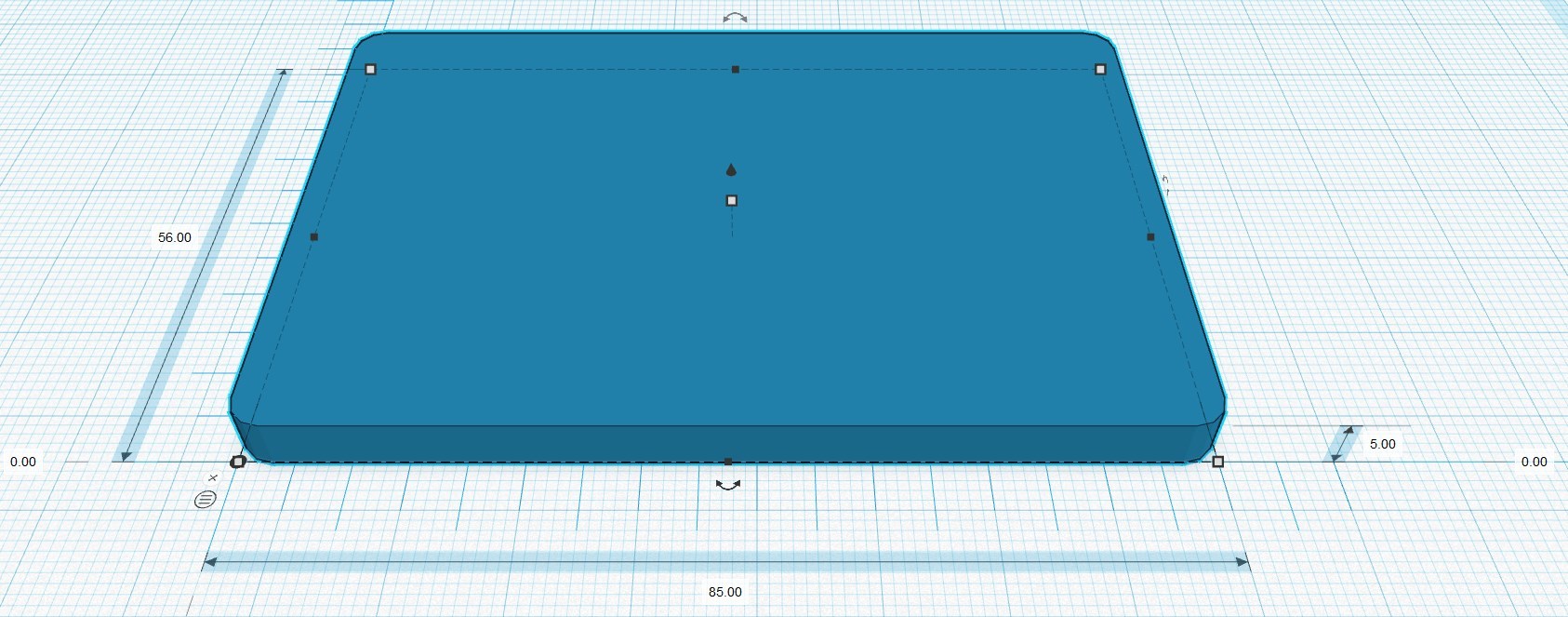
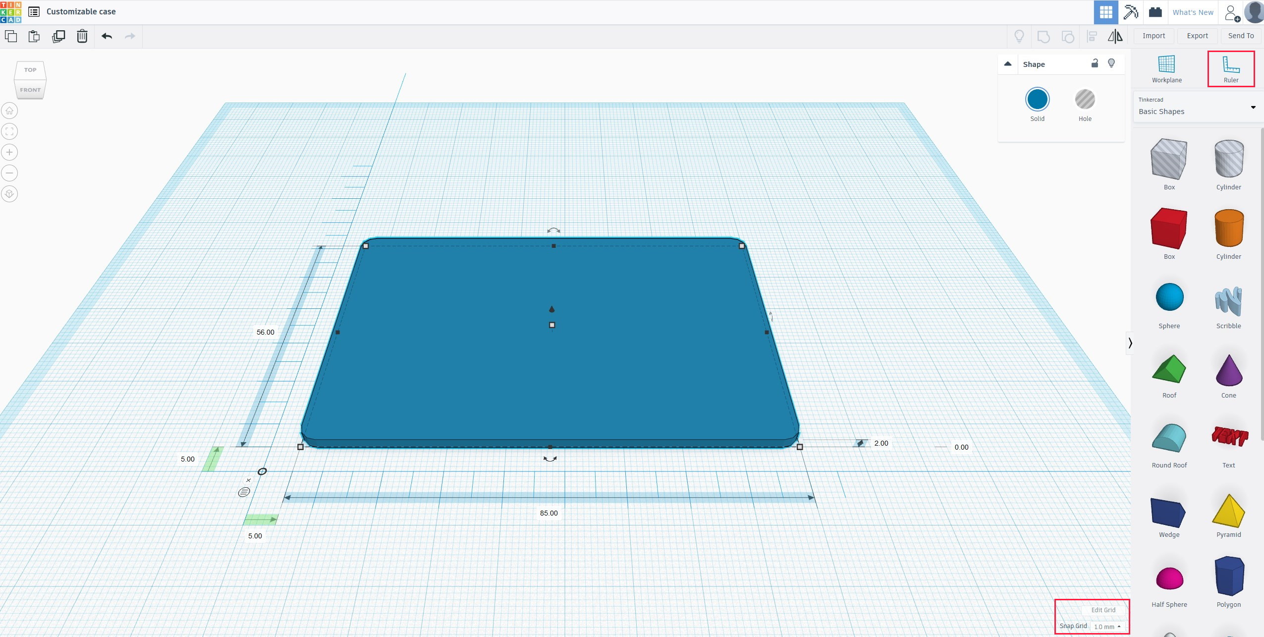
After importing our SVG model from LibreCasd or Inkscape into TkinterCad we will place some ruler, and change the greed space to 0.5 mm – it will significantly simplify components placement and dimensions control.
To place the ruler click on its button and then drag it to the Workplane where you would like the ruler to be positioned.
We can change the shape height, width and distance from the base point by using the dimensions on the ruler. The grid on the Workplane is like the X Y coordinate system. The ruler going from left to right is on the X-axis and the ruler going from bottom to top on the left side is on the Y-axis. We will move the plater closer to the corner by clicking once on the number for the vertical ruler (Y-axis), after that the value is in green and we will change the number to zero. The same for the X-axis - it is our 0.0 point.
You can use the arrow keys to move the selected shape with the increment according to the grid space. By default, the workspace has a grid snap size of 1 mm, as result our object will move 1mm by each arrow cay press.
To scale the object in TinkerCAD, first of all select it by clicking on it with LB, then click on one of the small white rectangles situated around the object (so called handles) and drag it. We will change the mounting panel thickness to 2 mm by changing the size directly or pooling the white rectangle.
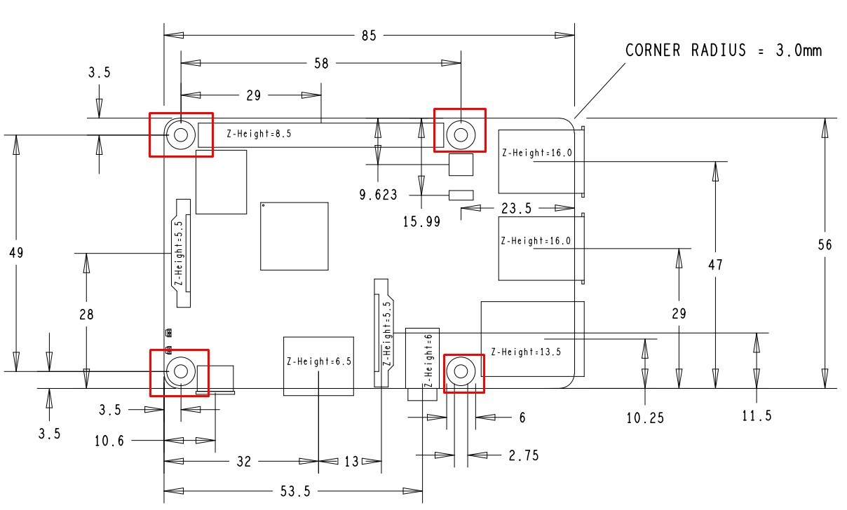
In our DFX file we don’t have mounting holes so we can draw it in LibreCAD or FreeCAD or directly in TkinterCAD. Dimensions for the holes we will take from the PI board mechanical drawing.
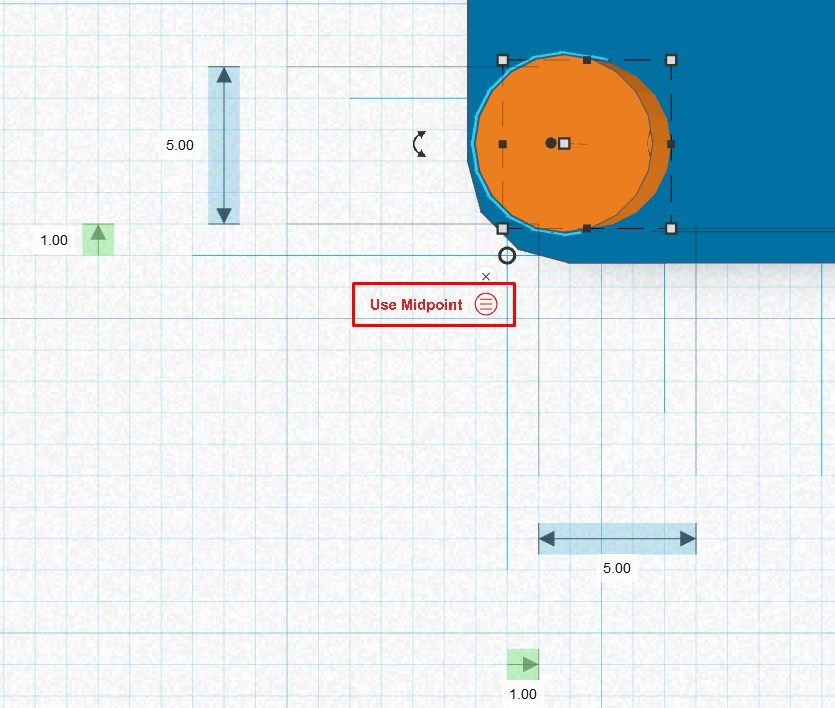
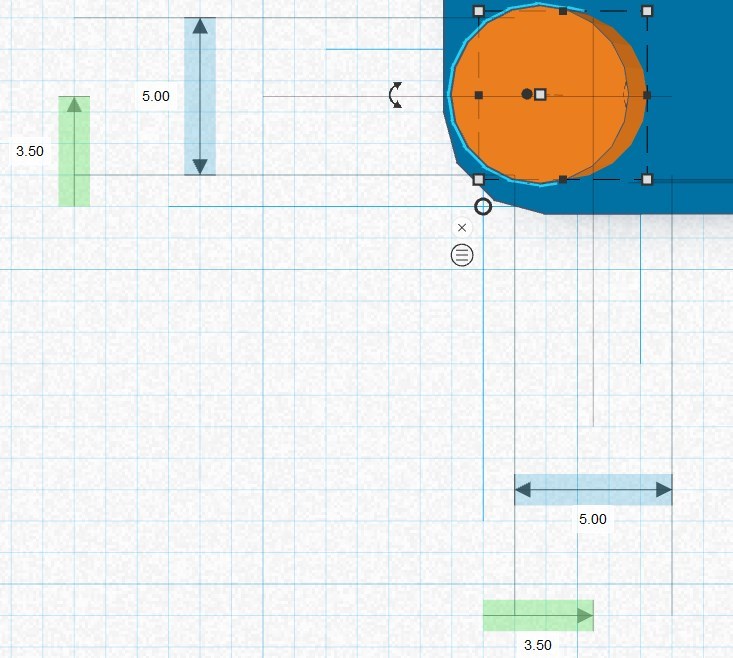
We don’t have a radius or diameter tool in TkinterCAD, but we can change the cylinder length and width. We will make H = 5 mm and B = 5 mm, so now our cylinder has a diameter of 5 mm. Our hole center is 3.5 mm in X and Y direction from the corner point.
By clicking in the ruler corner on Use Midpoint we can associate our dimensions with the circle center point and move it 3,5 mm (as shown in Raspberri Pi drawing) in X and Y directions.
As next step copy the cylinder with Ctr+C and paste it with Ctr+V and move it over the first cylinder by dragging with pressed LB on the black dot.
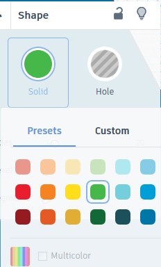
Change the color of the second cylinder by clicking in the shape property window on the associated button and select some color which you like. It is much easier to work with the shapes if they have a different shade. It is not affecting the color of the printed model, because it only depends on the paint of the used filament.
Change the cylinder diameter to 2.7 mm and the height to 3 mm. You can change the X and Y parameters manually by typing its value in the dimensions field or you can scale it proportionally in all directions by holding the Shift key while drugging some of the white handler (for easy use of this function change the grid snap to 0.1 mm).
Alignment Tool
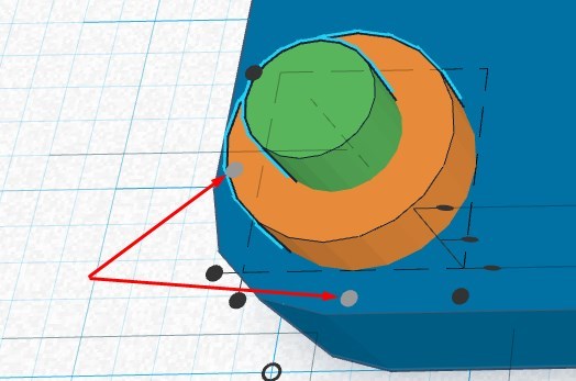
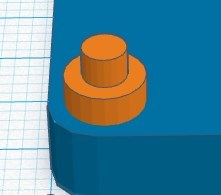
We can calculate the distance from the plate corner to the cylinder center in X and Y direction, which will be 3.5 mm – 2.7 mm/2 = 2.15 mm.
Alternatively we can use the alignment tool.
Align cylinders
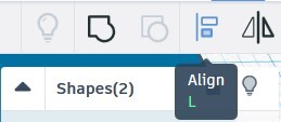
To make sure that the green cylinder is in the center of the orange cylinder, use the Align tool. Select both cylinders by holding Shift and click each object and then press the Align button in the alignment menu.
Look for the two in the middle located gray dots, and click on each to align the object in X and Y direction. By selecting other dots you can align the green cylinder horizontally or vertically.
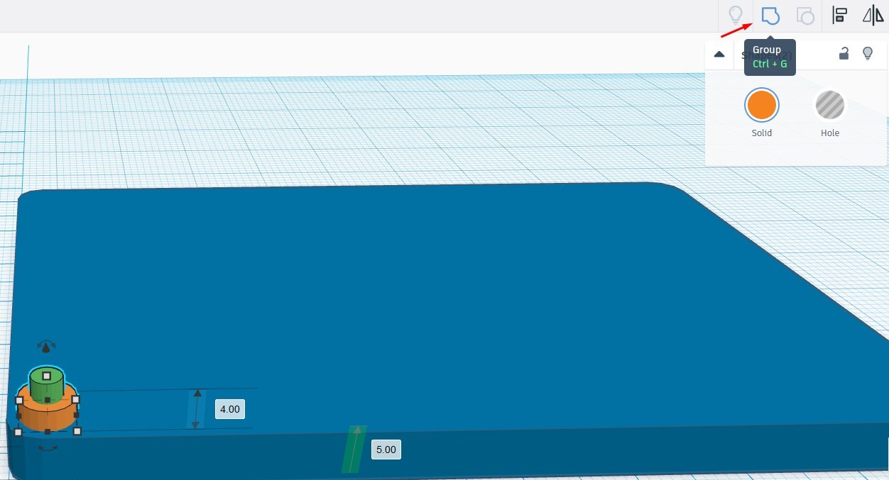
Now we can group our two cylinders by selecting both of them (hold Shift and click each with LB) and press the Group button.
After that we can perform “copy paste” (press Ctr + C to copy the shapes; press Ctr + V to paste a copy) and place our grouped object in the three remained corners with following dimensions:
Left top corner – X = 1 mm, Y = 50 mm
Right top corner– X = 59 mm, Y = 50 mm
Right bottom corner– X = 59 mm, Y = 1 mm
Placing circles can be done in LibreCAD or FreeCAD and then exported as SVG, but with manual placing we learned some basic functions and operations in TkinterCAD
Cut the Plate
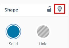
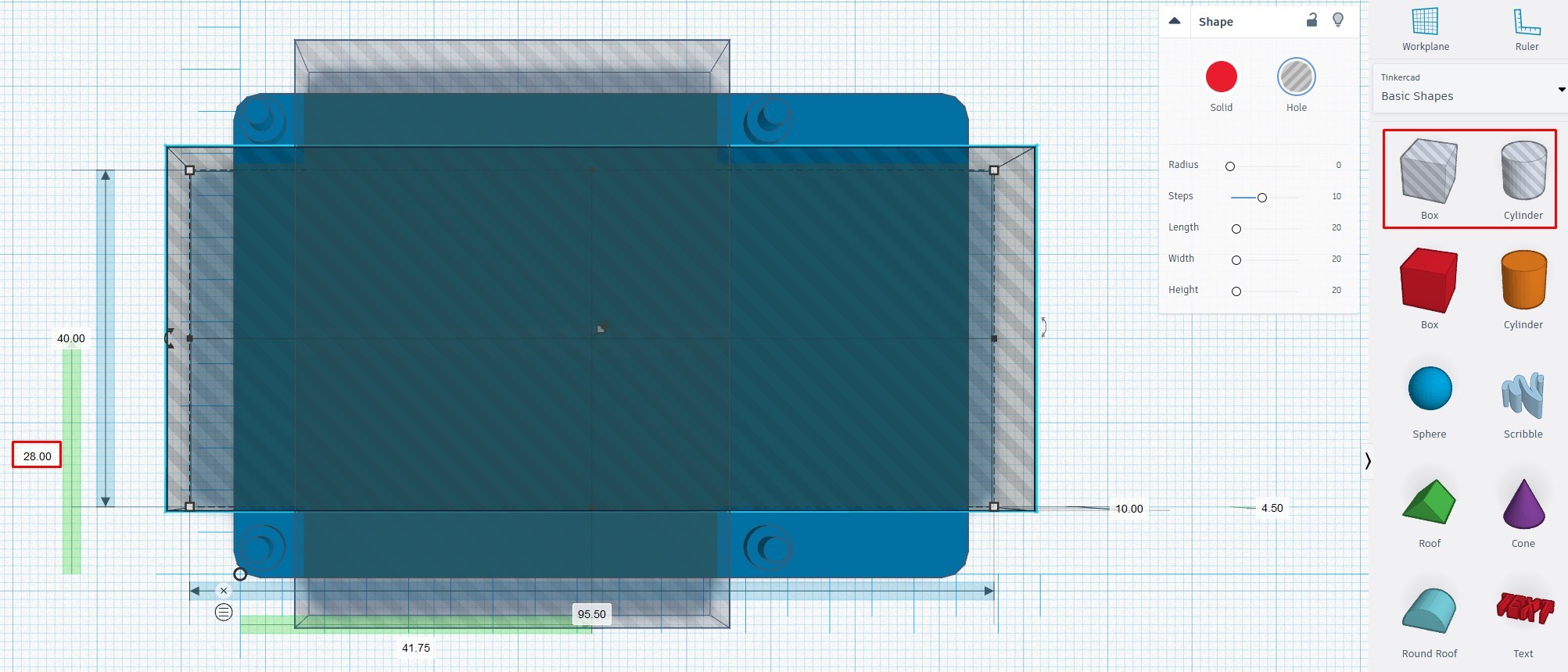
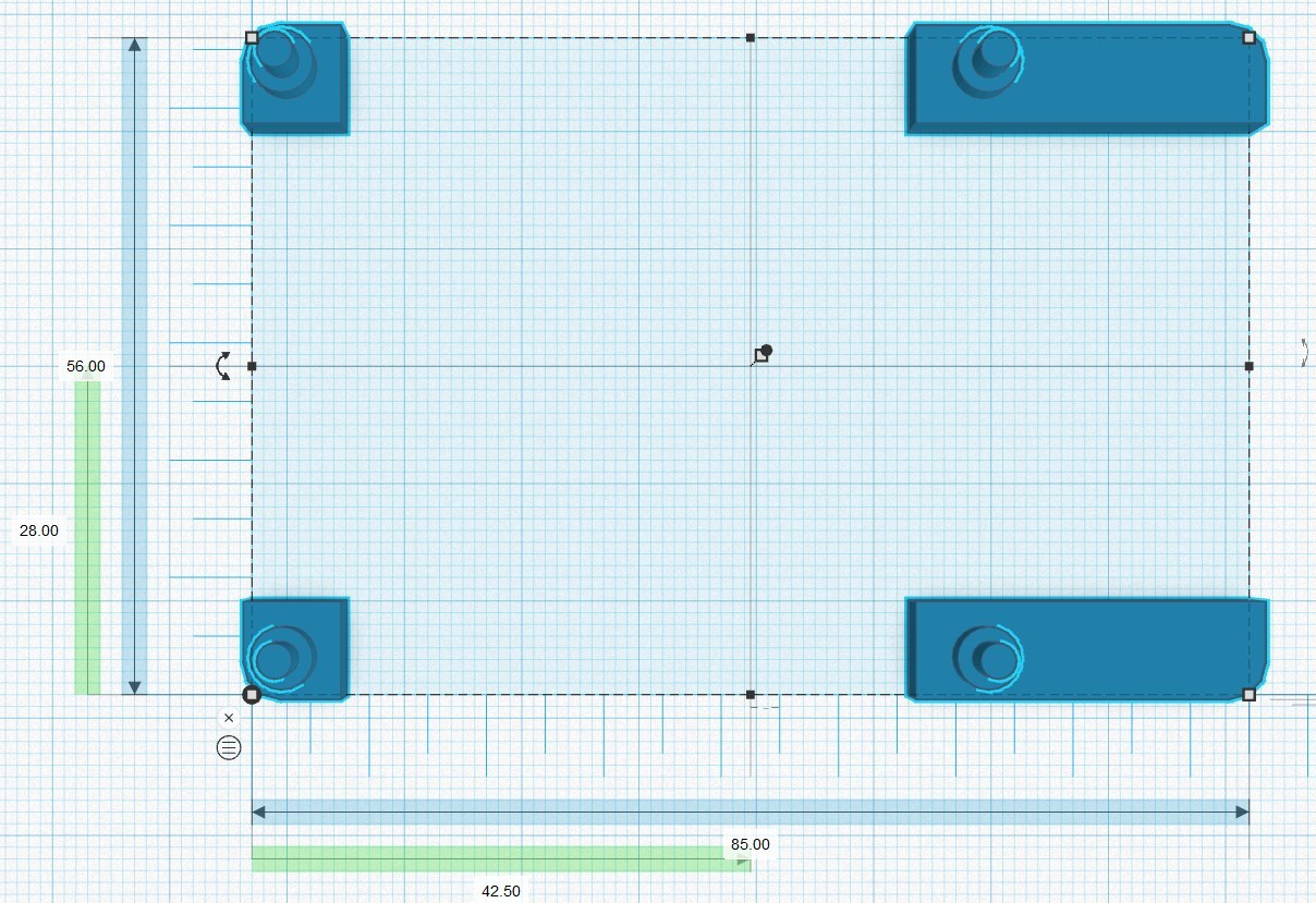
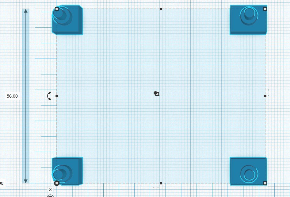
Make some copies of the plate (4 or 5), move them apart and leave one of them as it is and make the other invisible by clicking the Hide selected button.
Use the hole box object to create two boxes:
First box parameters: 28 mm to the center point in Y direction, 40 mm width and 90 mm lengt;
First box parameters: 32 mm to the center point in X direction, 48 mm width and 60 mm length;
Select all objects by clicking LB and dragging the selection box over all objects or by using the Ctr +A keyboard shortcut. When all objects are selected press the group button and our boxes will cut through the plate.
With the third box we will cut the remaining part of the plate.
Making the Pi Board Base

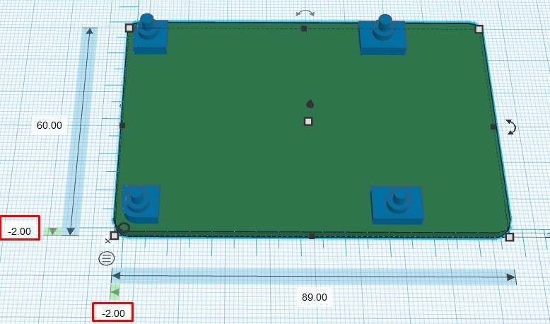
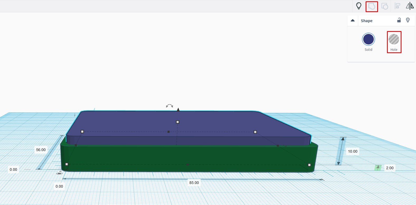

Make the second plate visible and place it in the original 0,0 position. Change the height to 2 mm and move the mounting points to the top of the plate.
Now we have the bottom part of our Raspberry Pi case.
After 5 minutes we have already created a 3D model of our Raspberry Pi 3 B+ mounting base.
To create walls we will increase the plate size by 2 mm on each side, and at the end our plate will be 89 mm long and 60 mm wide.
Here is where the magic begins through the extensive use of the positive and negative space concept of the TkinterCAD.
First of all move the mounting points 60 mm in Y direction, then increase the height of the plate to 10 mm after that make another plate visible, then change its height to 9 mm and rise it 2 mm over the Workplane. As a next step place it at the center of the first object and click on the Hole button, and then select both objects with Ctr +A and press the Group button.
Voila- magic has happened and a part of our case is ready.
Creating Case

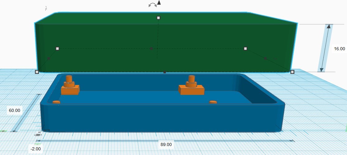

Copy the case bottom, place it above the first part and click the mirror button and then the top of the vertical arrow – it will create a mirror copy of the part (rotated by 180 °). And we can place our board mounting points back by changing the Y value from 60 mm back to 0.
Change the height of the top part to 16 mm and lower it to the first part.
First of all we will make the top part invisible and another copy of the original plate visible. It will be our reference Raspberry Pi board with 2mm thickness. It has to be placed 7 mm over the Workplane.
Cuts for the USB, HDMI, LAN and Audio Connectors
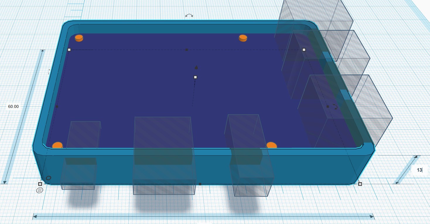
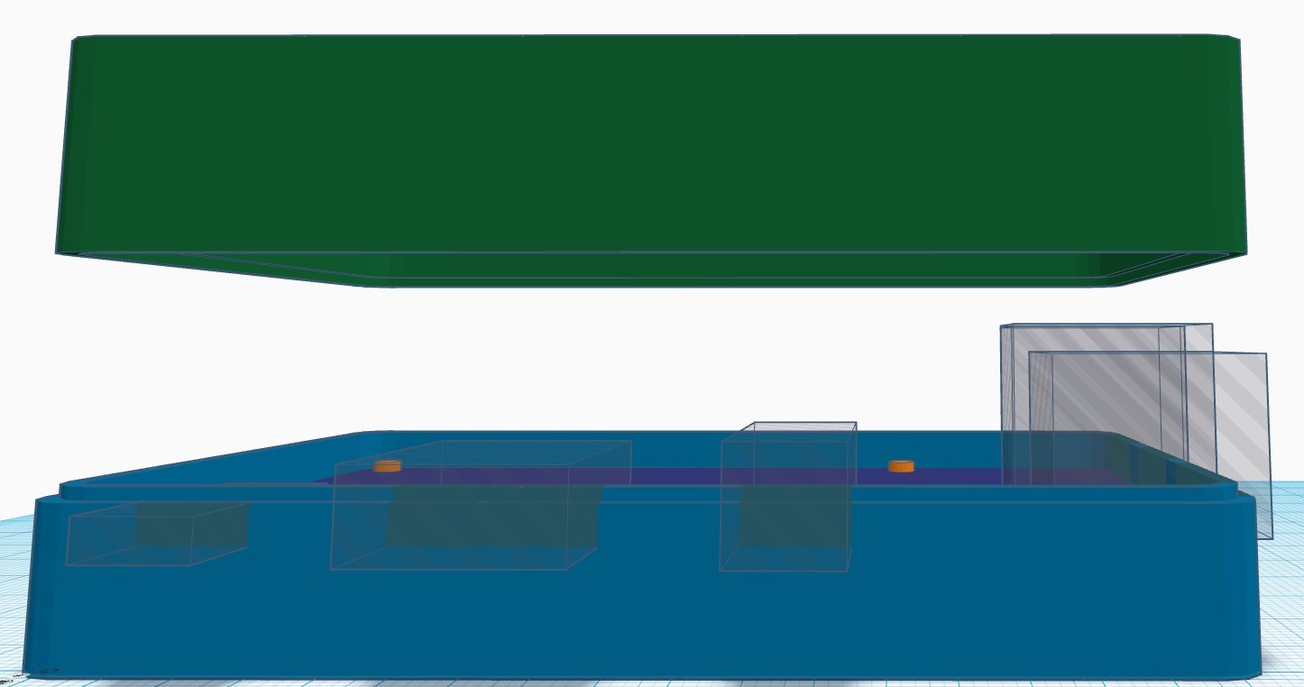
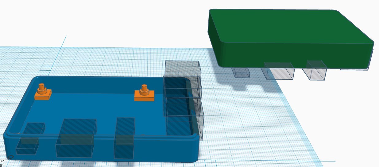
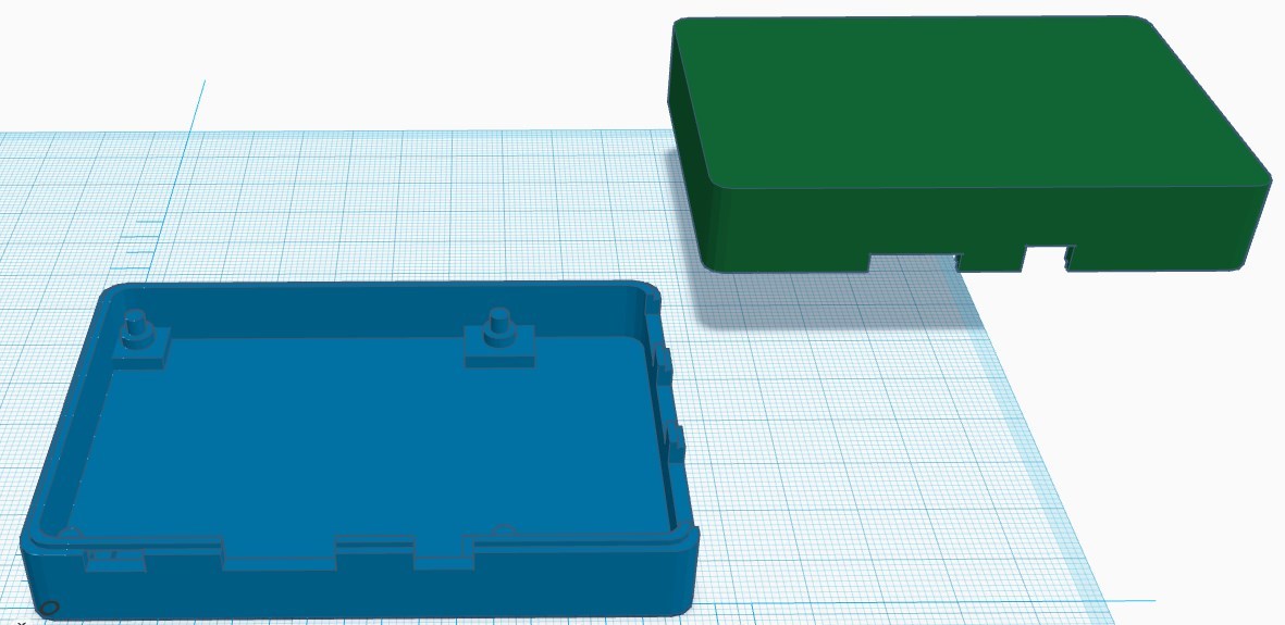
Now we have to perform some cuts for the USB, HDMI, LAN and Audio connectors.
We have all sizes in our technical drawing so we can place hole boxes with the same sizes as the connectors.
We will go from left to the right:
- first box is USB power with 3 mm height, 8 mm width and 10.6 mm to the middle point
- second box is HDMI connector with 6.5 mm height, 15 mm width and 32 mm to the middle point
- third box is Audio jack with a 8 mm diameter and 53.5 mm to the middle point
- fourth box is ETHERNET connection with 13.5 mm height, 16 mm width and 10.25 mm to the middle point in Y direction
- fifth box is the double USB connector with 16 mm height, 13 mm width and 29 mm to the middle point in Y direction
- the last box is the double USB connector with 16 mm height, 13 mm width and 47 mm to the middle point in Y direction
Next place hole boxes according to the connectors dimensions, and they should lay on our reference board – 9 mm over the Workplane.
After placing our negative space boxes we can see that the height of the bottom case should be increased to 13 mm.
We did forget some small detail, becouse our case parts should fit to each other, as a result we need to perform some offsets.
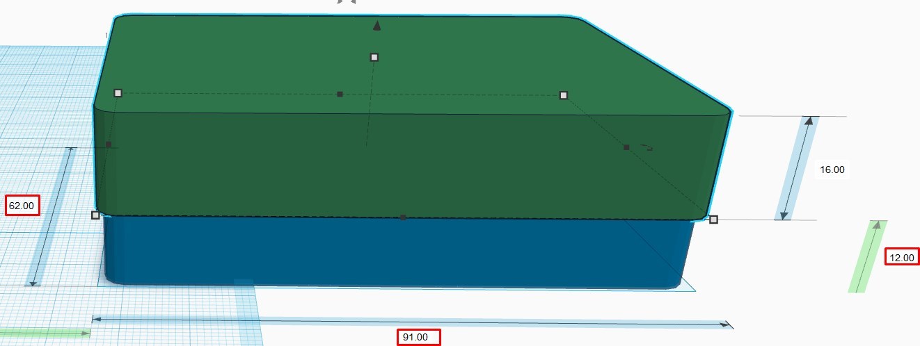
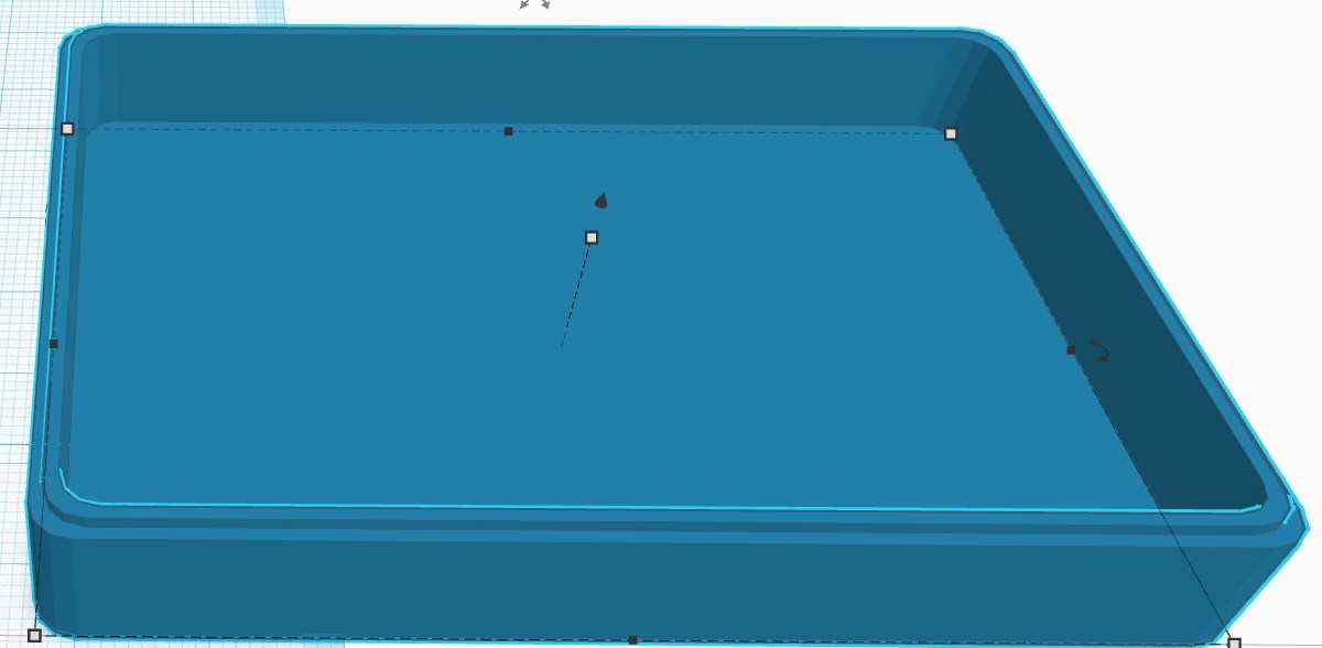
Let’s move our case parts to the side and perform some offset, by 1 mm outside of the bottom part and 1 mm inside the top part.
We made a copy of our case, moved it to the side, and increased the size of the top case part by 1 mm to each side, and lowered it 1mm down so that it’s Intersects with the bottom part. After that we apply the Hole button to the case cover, then select the both parts and press Group.
Now we can perform the same operation with the top part, or we can rotate it by 180°, by using the rotating handler, so that we can make another plate visible, increase its height and width by 2 mm to each side, position it and perform Hole and Group operations. After that we will have to parts which will perfectly fit to each other.
Furthermore we will delete our reference plate, lower our top part down (in our case 12 mm) to the workplace. Now we come to a bit of tricky part – we must create a copy of the assembled case, move it apart and then in the original case we will remove the top part, thereafter we will select the remaining components and press Group button, lastly with the copy we will perform the same operation but only without the bottom part.
Ventilation Openings
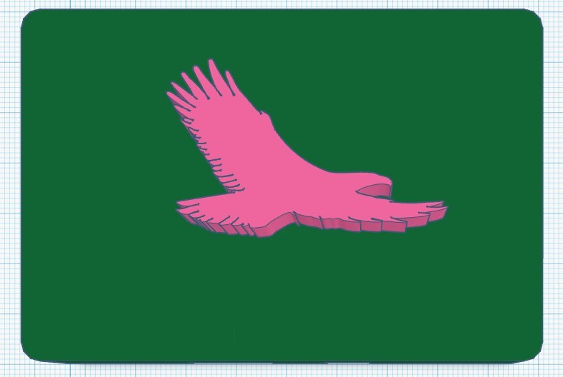
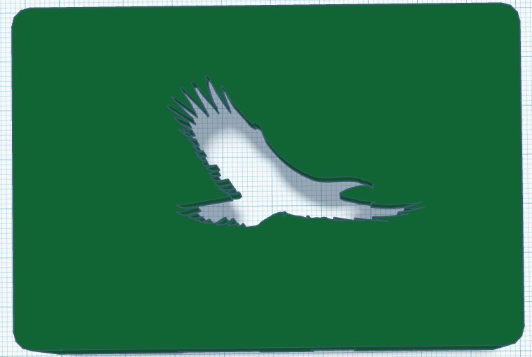

Our Raspberry Pi board case is ready.
To prevent Raspberry Pi from overheating we are forced to place some ventilation openings. I prefer to use some nature motives like trees or animals – so I imported Eagle.svg, and then scaled and placed it on the case cover. After that with the selected eagle profile I clicked Hole button and then with pressed Shift additionally selected the case cover and pressed Group button.
One small addition – I forgot to make an openings for the SD card. The SD card slot positioned in the middle of the Raspberry PI – board and is 12 mm wide; so we can made a cut by using Box object which is 14 mm wide, has a height of 2 mm and placed 28 mm in Y direction and 7 mm from Workplane.
Downloads
Preparing for 3D Print
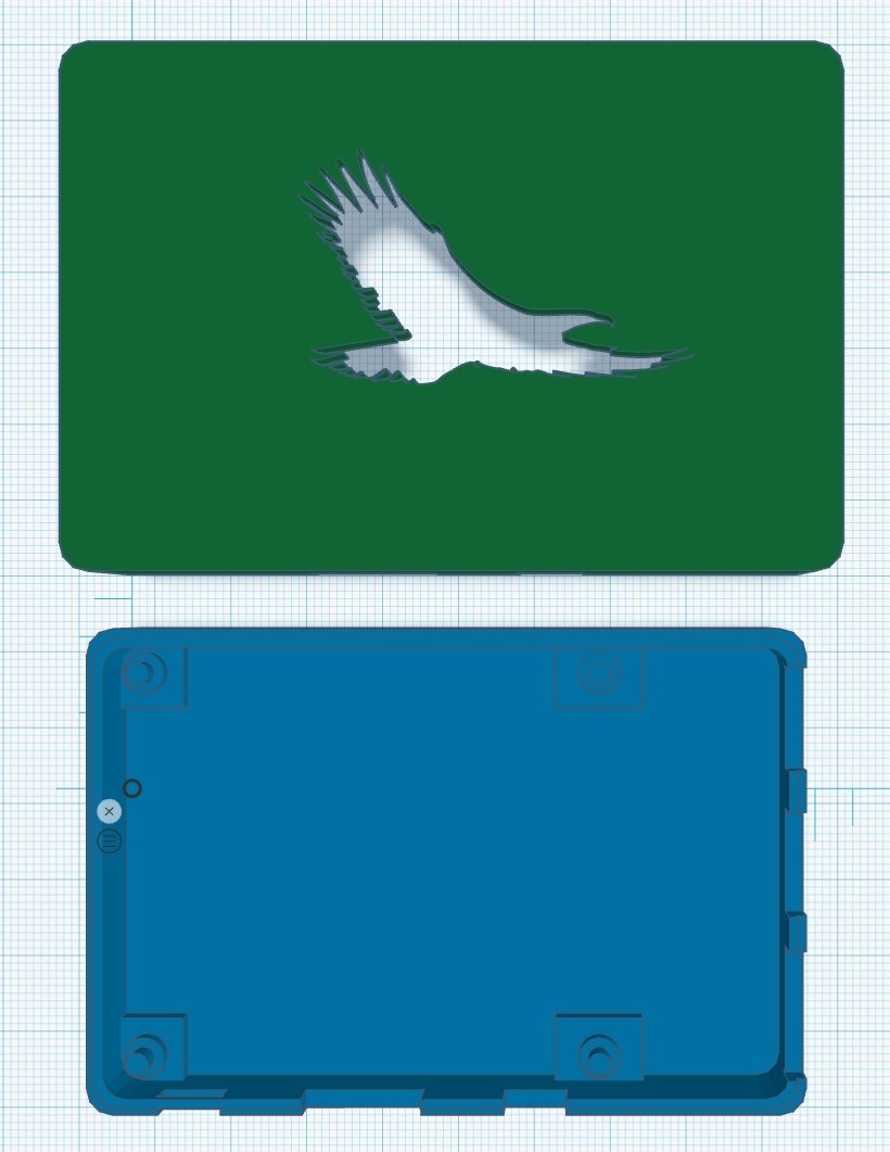
For the 3D print we need to place both our parts beside each other and they have to lay exactly on the Workplane. It is better to double - check that parts are not floating above the Workplane, by rotating the model and view your shape from the front, additionally re-examine the dimension from the plane to the model (it has to be exact 0 mm). Otherwise it will mess up with your 3D-Print.
You can place some other SVG graphics, cut additional halls for the GPIO pins or camera connections etc.
Now we can export our model for the 3D Print.
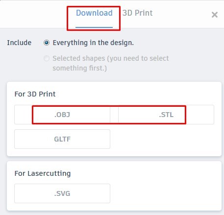
1. Click the Export button
2. In the pop up dialog window select Download button
3. Choose the file format for your 3D print (OBJ or STL).
You can decide which file format best suits you:
- STL (STereoLithography) file format is widely accepted by 3D printing software. The STL file needs to be processed by a software called “slicer”, which converts the 3D model into a series of thin layers and produces a G-code file containing instructions for a specific type of 3D printer.
- OBJ (Wavefront OBJ File Format) is more complex than the STL format and contains texture, colors and other CAD parameters of the 3D object. It is supported by most 3D Printers and works perfect with multicolor 3D printers.
I have a very simple 3D printer so I export the case model in the STL format.
Cura Software is a popular free “slicer” software
Some Resume
1. First we placed mounting points for the Raspberry Pi 3B (B+) board. Thanks to those mounting points our board will be spaced 5 mm over the case bottom, which gives enough space for the heat sink.
2. This case is for Raspberry Pi 3 (B+) board types, but you can easily adjust this case for some other Raspberry Pi models. You can scale the case, and after ungrouping the bottom part you can move the mounting points according to the new dimensions. I placed different models of the case at the GitHub (https://github.com/EcoEngineering/Arduino_PI-Case-in-TkinterCAD), so you can take case models without ventilation cuts and place your own vector graphics there.
3- TkinterCAD has some restrictions in creating complex 3D models or shapes, but you can always design your component, in other CAD programs (like FreeCAD, LibreCAD etc.) or even in some image manipulation software ( GIMP, Inkscape) and after saving it in SVG format import it in TkinterCAD.
If you have some problems with SVG import - then first restart TkinterCAD, and if this is not help check that your image is a closed vector graphic. For example in Inkscape you can go to the Path – Trace Bitmap and play with some parameters until you will get an appropriate result; in the same way you can create SVG graphics from some JPG, PNG, BMP files. Try to save your design as a block In CAD program.
In the next tutorial I will explain how to use Cura slicer to slice our model and how to play with different 3D printer options – to optimize your print.