Creating a Car Lighting System With Tinker CAD
939 Views, 0 Favorites, 0 Comments
Creating a Car Lighting System With Tinker CAD
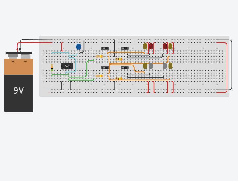
This guide will teach you to create a car lighting system with indicators, headlights, and brake lights made in tinker CAD. This guide assumes that you are creating this circuit in tinker CAD and some components/steps may not be listed or applicable for other programs or a real model. This guide also assumes novice tinker CAD skills and experience such as finding and placing components as well as changing values of resistors and capacitors. This project allows for greater understanding of everyday electrical circuitry and will increase your proficiency with tinker CAD.
This project can be found at: https://www.tinkercad.com/things/i5SMOtM9spD-swanky-jarv
Supplies
The components needed to create this circuit are:
-1 breadboard
-1 9V battery
-1 10μF capacitor
-1 555 Timer IC
-1 50kΩ resistor
-4 340Ω resistors
-4 slide switches
-4 yellow LED's
-2 red LED's
-2 white LED's
Powering the Circuit
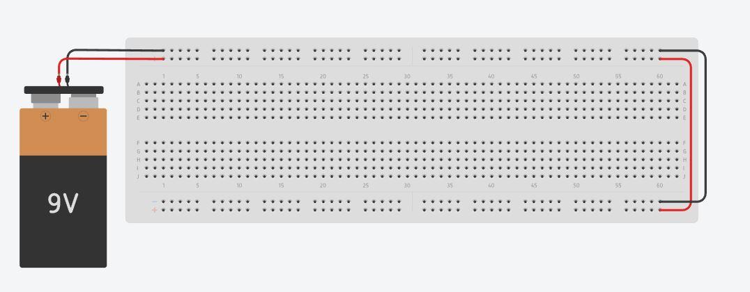
Powering the circuit is the first step and the power rails either side of the breadboard make for convenient sources of power and allow for organised wiring.
- Connect the battery terminals to the power rails of the bread board. Don't forget to power both sides.
TIP: Colour coding the wires allows for easy troubleshooting and neat circuitry.
Creating the Timer Circuit
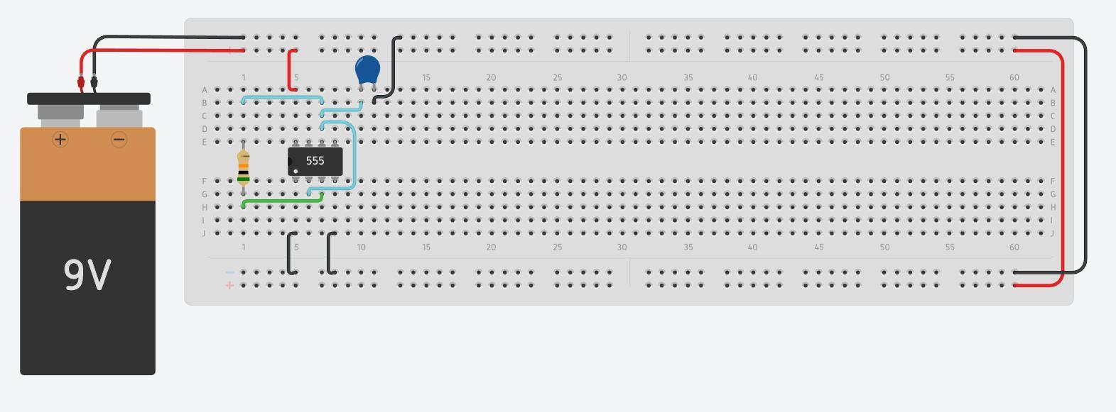
This step will produce the circuit that makes the indicator lights (Yellow LED's) blink when turned on.
- Place the 555 timer, the capacitor, and the 50kΩ resistor in the configuration found in the image.
- Connect the Ground and Reset terminals of the 555 timer to the negative power rail. Connect the Power terminal to the positive rail.
- Connect the Trigger terminal of the 555 timer to the Threshold terminal .
- Now connect a terminal of the capacitor to the Threshold terminal and the other terminal of the capacitor to the negative power rail.
- Connect one end of the 50kΩ resistor to the Threshold terminal and the other to the Out terminal .
Placing the Switches
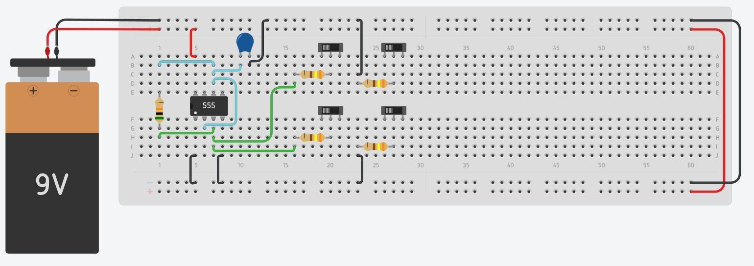
This step will see you creating the control board for the lights. The left switches will control the indicator lights both left and right, the top right switch will control the break lights and the bottom right will control the headlights.
- Place the 340Ω resistors and the slide switches in this configuration.
- Connect the left terminal of both the right resistors to the negative power rail.
- Now connect the left terminal of the left resistors to the Out terminal of the 555 timer.
Placing and Connecting the LED's
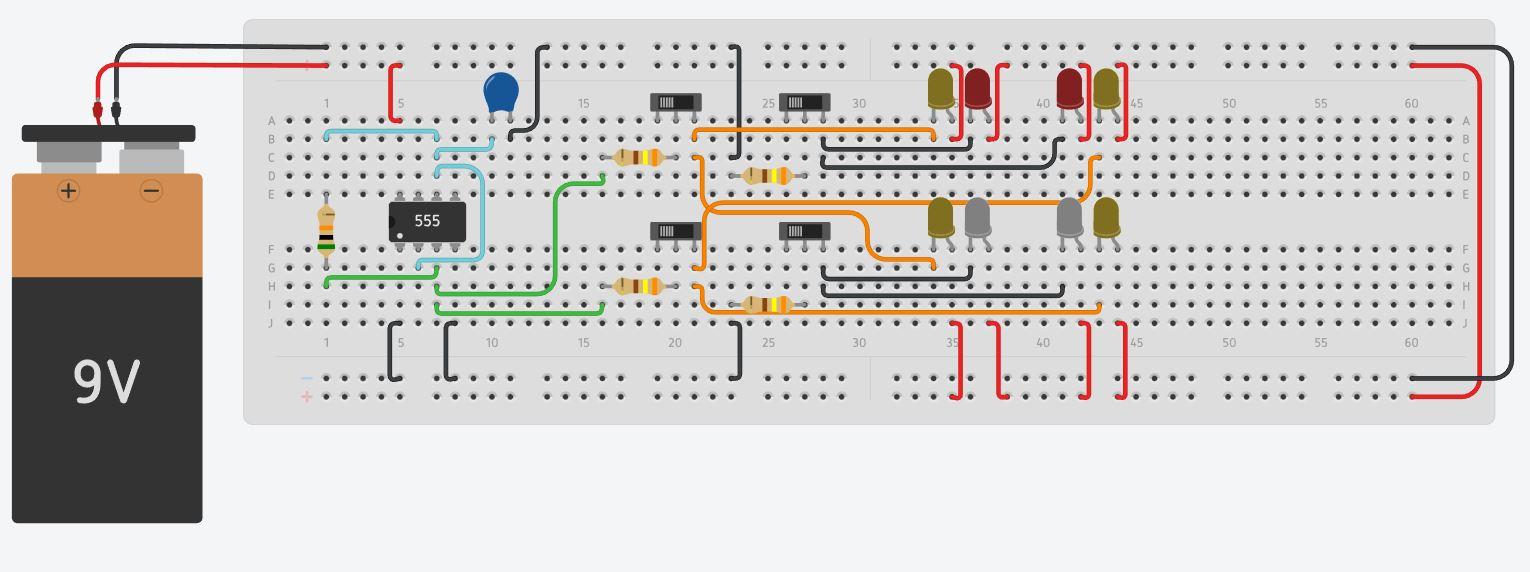
This is the final step of creating the circuit.
- Place the LED's in this configuration.
- Then, connect the anode of each LED to the positive power rail.
- Connect the cathode of the red LED's to the right terminal of the top right switch.
- Connect the cathode of the white LED's to the right terminal of the bottom right switch.
- Connect the cathode of the left yellow LED's to the right terminal of the top left switch.
- Connect the cathode of the right yellow LED's to the right terminal of the bottom left switch.
Challenges
For those who want to challenge themselves, bellow is a list of additions to the circuit that will improve it to the next level and develop your skills in tinker CAD.
- Make the headlights have adjustable brightness.
- Add a window wiper.
- Create the timer circuit with an Arduino.
Well done on creating you own car lighting system.